Popov V.N., Lambin P. (eds.) Carbon Nanotubes
Подождите немного. Документ загружается.

*To whom correspondence should be addressed. Marie-Faith Fiawoo; e-mail: fiawoo@onera.fr
47
V.N. Popov and P. Lambin (eds.), Carbon Nanotubes, 47–48.
© 2006 Springer. Printed in the Netherlands.
TEM SAMPLE PREPARATION FOR STUDYING THE INTERFACE
CNTS-CATALYST-SUBSTRATE
MARIE-FAITH FIAWOO, ANNICK LOISEAU
LEM UMR 104 CNRS/ONERA, 92322 Châtillon, France
ANNE-MARIE BONNOT, ANTONIO IAIA
LEPES-CNRS UPR11, 38042 Grenoble, France
VINCENT BOUCHIAT
CRTBT-CNRS UPR5001, 38042 Grenoble, France
JANY THIBAULT
TECSEN CNRS UMR 6122, Univ. Paul Cézanne, 13397
Marseille, France
Abstract. We study by Transmission Electron Microscopy (TEM) in-situ self-
assembled carbon nanotubes (CNTs) grown by the Hot Filament Chemical
Vapor Deposition (HFCVD) process on silicon substrates used for electronic
devices. We present the different methods we have developed for extracting
CNTs and studying their interface with the substrate as they are observable by
TEM.
Keywords: TEM preparation technique, nanotubes, SACT, cleavage, ion milling
For studying specimens by TEM and performing analysis (EFTEM, EELS), the
sample needs to be thin (20 to 30 nm), transparent to electrons, smaller than 3
nm diameter to fit in the TEM holder and keep its intrinsic features. We want to
study the interface CNTs-catalyst-substrate in localized CNTs synthesis (Marty
et al., 2002) aiming to understand the CNTs growth by Chemical Vapor
Deposition (CVD) process like previously done for high temperature synthesis
(Loiseau et al., 2004). Here we present different preparation methods which we
tried in order to reach the required thickness necessary for the study of the
interface of nanotubes with a single crystal silicon substrate.
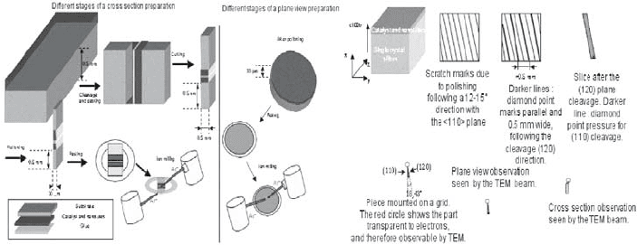
Four types of preparation have been tested: scratching the sample, ion
milling, Si
3
N
4
membrane system, and small angle cleavage technique (SACT).
48
Some of them enable plane view, cross-section observations or both. Scratching
the sample with a tweezer or a diamond scribe to deposit on a TEM grid seldom
enables observations of the interface because of the thickness of the piece
scratched. Ion milling technique involves a mechanical polishing before
thinning the sample by pulling out atoms of the sample with an ion beam of
argon Ar+ (Fig. 1, left). A disadvantage of this technique is the introduction of
artifacts. The Si
3
N
4
membrane with a rectangular hole has CNTs grown on the
membrane as well as across the hollow. Unfortunately, the hole's edge in not
thin enough to see the interface. SACT consists in cleaving the sample along
the (120) and (110) planes, which form an angle of 18.43° (Fig. 1, right). This
small angle of the apex of the sample allows its transparency to electrons
(Walck et al., 1997). The disadvantage of this technique is the small area
transparent to electrons, which is not adapted for a sample having a few CNTs.
Figure 1. Left: Ion milling preparation stages; Right: Different stages of SACT.
For the time being, the ion milling technique is the only one, which enables
the systematical observation and analysis of the interface. Further
investigations, such as focused ion beam cutting and other membrane systems,
are presently being carried out.
References
Marty, L., Bouchiat, V., Bonnot, A.M., Chaumont, M., Fournier, T., Decossas, S., and Roche, S.
2002, Batch processing of nanometer-scale electrical circuitry based on in-situ grown single-
walled carbon nanotubes, Microelectronic Engineering 61-62:485-489.
Loiseau, A., Gavillet, J., Ducastelle, F., Thibault, J., Stéphan, O., Bernier, P., and Thair, S., 2004,
Nucleation and growth of SWNT: TEM studies of the role of the catalyst, C. R. Physique
4:975-991.
Walck, S.D., and McCaffrey, J.P, 1997, The small angle cleavage technique applied to coatings
and thin films, Thin Solid Films 308-309:399-405.
*To whom correspondence should be addressed. Roman Caudillo; email: rcaudillo@mail.utexas.edu
49
V.N. Popov and P. Lambin (eds.), Carbon Nanotubes, 49–50.
© 2006 Springer. Printed in the Netherlands.
A METHOD TO SYNTHESIZE AND TAILOR CARBON NANOTUBES
BY ELECTRON IRRADIATION IN THE TEM
R. CAUDILLO,* M. JOSÉ-YACAMAN
Materials Science and Engineering and Texas Materials Institute,
University of Texas at Austin, 1 University Station C2201, Austin,
Texas 78712, USA
H. E. TROIANI
Centro Atómico Bariloche and Instituto Balseiro, CNEA and
UNC, 8400 Bariloche, Rio Negro, Argentina
M. A. L. MARQUES, A. RUBIO
Donostia International Physics Center, Paseo Manuel Lardizábal
4, 20018 San Sebastián, Spain
Abstract. Carbon nanotubes (CNTs) can be synthesized from amorphous
carbon thin films by electron irradiation in the transmission electron microscope
(TEM). We propose that irradiation effects impart a tensile stress and introduce
defects to a CNT thus formed and show that the CNTs can be made to fracture
by a brittle or ductile mechanism. We also report a healing of the carbon film
that is observed after some critical amount of irradiation.
TEM is normally only used to characterize CNTs synthesized by standard
techniques, such as arc discharge, laser ablation, or chemical vapor deposition
(CVD); however, Troiani et al.
1,2
have shown that it is also possible to use
electron irradiation in a TEM to construct single-walled carbon nanotubes
(SWCNT) from an amorphous carbon film. In this method, two through-holes
are created in an amorphous carbon film using electron-beam irradiation in a
TEM. A thin graphitic fiber forms in between the two holes and is narrowed
until forming a SWCNT. Here we show that by controlling the current density
on a CNT formed by this technique, it is possible to cause fracture and to
observe the fracture mechanism in the TEM. We observe that the CNT fractures
either by a brittle or ductile fracture mechanism, depending on the amount of
current density on the sample.
50
We propose two mechanisms working to achieve the narrowing of the
bridge: (1) deformation in response to an axial stress resulting from a
contraction of the film due to radiation-induced graphitization and (2) creation
of defects in the bridge due to irradiation, resulting in vacancy clustering that
leads to brittle fracture or atomic rearrangements that lead to plastic fracture.
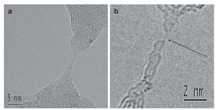
Figure 1 shows CNT formation at the neck of a bridge and the formation of a
linear chain of carbon atoms during the ductile deformation of the CNT.
Figure 1. (a) TEM image showing the formation of a CNT at the neck of a bridge, (b) TEM image
showing the formation of a linear chain of carbon atoms (signaled by arrow) in a CNT neck that
has undergone ductile deformation.
We also observe a surprising phenomenon during prolonged irradiation of
carbon nanotubes and carbon nanofibers formed by electron irradiation in the
TEM, in which a sudden diffusion of carbon atoms to the bridge structure and
periphery of the holes results in a reconstruction of the carbon film, which in
some cases results in a complete closing of the holes.
3
These results indicate that CNTs, as well as other carbon nanostructures, can
be synthesized and tailored by electron irradiation, and suggests the possibility
of larger scale, carbon nanostructure design by e-beam lithography and
complementary techniques.
References
1. H. E. Troiani, M. Miki-Yoshida, G. A. Camacho-Bragado, M. A. L. Marques, A. Rubio, J. A.
Ascencio, and M. Jose-Yacaman, Direct observation of the mechanical properties of single-
walled carbon nanotubes and their junctions at the atomic level, Nano Letters 3(6), 751-755
(2003).
2. M. A. L. Marques, H. E. Troiani, M. Miki-Yoshida, M. Jose-Yacaman, and A. Rubio, On the
breaking of carbon nanotubes under tension, Nano Letters 4(5), 811-815 (2004).
3. R. Caudillo, H. E. Troiani, M. Miki-Yoshida, M. A. L. Marques, A. Rubio, and M. Jose-
Yacaman, A viable way to tailor carbon nanomaterials by irradiation-induced
transformations, Radiation Physics and Chemistry (In Press) (2005).
51
V.N. Popov and P. Lambin (eds.), Carbon Nanotubes, 51–52.
© 2006 Springer. Printed in the Netherlands.
SCANNING TUNNELING MICROSCOPY STUDIES OF NANOTUBE-
LIKE STRUCTURES ON THE HOPG SURFACE
I. N. KHOLMANOV,
1,2 1 1
1 1,3
1
INFM and Dipartimento di Matematica e Fisica, Università
Cattolica del Sacro Cuore, Via dei Musei 41, 25121 Brescia, Italy
2
Thermophysics Department, Academy of Sciences, Katartal str.,
28, 700135 Tashkent, Uzbekistan
3
Laboratorio Nazionale TASC-INFM, Strada Statale 14, Km
163.5, Basovizza, I-34012 Trieste, Italy
Abstract. We have studied the scanning tunneling microscopy tip interaction
with the naturally formed nanotube-like (NTL) structures on highly oriented
pyrolytic graphite (HOPG) surface. Shape variations of the NT-like structures,
caused by the modulation of scanning parameters, were observed and analyzed.
Keywords: STM; highly oriented pyrolytic graphite; nanotube-like structures
Scanning tunneling microscopy (STM) and spectroscopy (STS) are widely
employed to obtain information on local electronic properties, surface
geometry, and nanostructure-surface interactions.
1
We report on STM studies of the NTL structures formed on HOPG surface.
STM (OMICRON ultra-high vacuum (UHV) system) measurements have been
carried out in UHV at room temperature, in constant-current mode using
tungsten tips. HOPG specimen has been prepared by cleaving (adhesive tape) in
air, and annealed in UHV chamber at 900 °C.
Naturally-formed NTL structures located on steps were formed by the
spontaneous folding of the HOPG graphene sheets, or by STM tip
manipulation.
2
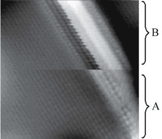
The NTL, presented in Fig. 1, is located at a HOPG step edge,
with an apparent width of 1.77 nm. The height difference of the graphene layers
between the right and left side of the NTL structure is 0.86 nm, quite close to
M. CASELLA, M. SANCROTTI
M. FANETTI, L. GAVIOLI,
52
the height of two graphene sheets. The image has been acquired with two
different tunneling currents, corresponding to region A (0.1 nA) and B (0.2 nA),
respectively. Region A corresponds to the typical appearance of the NTL
structure with continuity of the distorted graphite lattice on the curved structure.
Figure 1. STM image (8u8 nm2) of NTL structure on the step edge of the HOPG graphene sheet.
Scanning parameters: gap voltage +0.253 V and current 0.1 nA (region A) and 0.2 nA (region B).
Variation of tunneling parameters leads to dramatic changes of the NTL
apparent shape. In region B, the NTL presents a large modification of the NTL
curvature that becomes a large depression in the graphite structure. The
maximum depth of the depression, with respect to the unmodified structure, is
0.4 nm. Such variation is not observed when the tip is moving from right side to
left side of Fig.1, i.e., the backward direction. Hence the shape change behavior
is asymmetric. The NTL recovers its original shape by simply restoring a lower
current, without presenting any hysteresis in the apparent height variation.
These observations suggest that the deformations may actually be induced
by the modification of the tip-substrate interaction strength, and that the NTL
structure reacts in an elastic way to the STM tip. Although these features may
support deformation-based mechanism of the shape-changes, further detailed
analysis is required to elucidate the obtained experimental results. The results
suggest a possible development of STM as a tool to investigate the mechanical
properties of nanosystems.
References
1. T. W. Odom, J. H. Hafner, Ch. M. Lieber, in: Carbon Nanotube: Synthesis, Structures,
Properties and Applications, edited by M. S. Dresselhaus, G. Dresselhaus and Ph. Avouris
(Springer-Verlag, Berlin, 2001) pp. 177-215.
2. H.-V. Roy, C. Kallinger, B. Marsen, and K. Sattler, J. Appl. Phys. 83, 4695-4699 (1998).
*To whom correspondence should be addressed. Antal Koós; e-mail: koos@mfa.kfki.hu
53
V.N. Popov and P. Lambin (eds.), Carbon Nanotubes, 53–54.
© 2006 Springer. Printed in the Netherlands.
INFLUENCE OF CATALYST AND CARBON SOURCE ON THE
SYNTHESIS OF CARBON NANOTUBES IN A SEMI-CONTINUOUS
INJECTION CHEMICAL VAPOR DEPOSITION METHOD
Z. E. HORVÁTH, A. A. KOÓS,* Z. VÉRTESY, L. TAPASZTÓ,
Z. OSVÁTH, P. NEMES INCZE, L. P. BIRÓ
Research Institute for Technical Physics and Materials Science,
P.O. Box 49, H-1525, Budapest, Hungary
K. KERTÉSZ, Z. SÁRKÖZI, AL. DARABONT
Babes-Bolyai University, Faculty of Physics, Kogãlniceanu 1,
RO-3400, Cluj-Napoca, Romania
Abstract. The injection chemical vapor deposition (CVD) method allows the
semi-continuous production of pure multi-wall carbon nanotubes (MWCNTs).
In order to find the most efficient catalyst material and carbon source, we
investigated the quality and quantity of carbon nanotubes, when different
metallocenes (ferrocene, cobaltocene and nickelocene) and hydrocarbons
(benzene, toluene, xylene, cyclohexane, cyclohexanone, n-hexane, n-heptane,
n-octane and n-pentane) are injected into the reaction furnace. The obtained
samples were analyzed by Transmission Electron Microscopy (TEM). The
highest yield and the best quality were obtained when a mixture of ferrocene-
nickelocene was used as catalyst and xylene as carbon source. The weight of
purified carbon nanotubes was higher than 50% of the weight of catalyst
material for xylene and reached the 10% for all investigated carbon sources.
Keywords: carbon nanotubes; chemical vapour deposition; electron microscopy
The major advantage of the injection CVD method is the in-situ and continuous
generation of catalytic particles throughout the entire growth cycle. Therefore,
the injection CVD method does not need a catalyst synthesis step and can be
scaled up for continuous or semi-continuous production. We investigated the
quality and quantity of carbon nanotubes when different metallocenes and
hydrocarbons were injected into the reaction furnace.
54
We used the following reaction parameters: 6 g metallocene in 100 ml
hydrocarbon catalyst concentration (except for the cases when the solubility of
the metallocene in the hydrocarbon was too low), 1 ml/min solution flow-rate,
875 °C furnace temperature and 500 l/h Ar (carrier gas) flow-rate. The samples
were purified using a 45% HNO
3
aqueous solution.
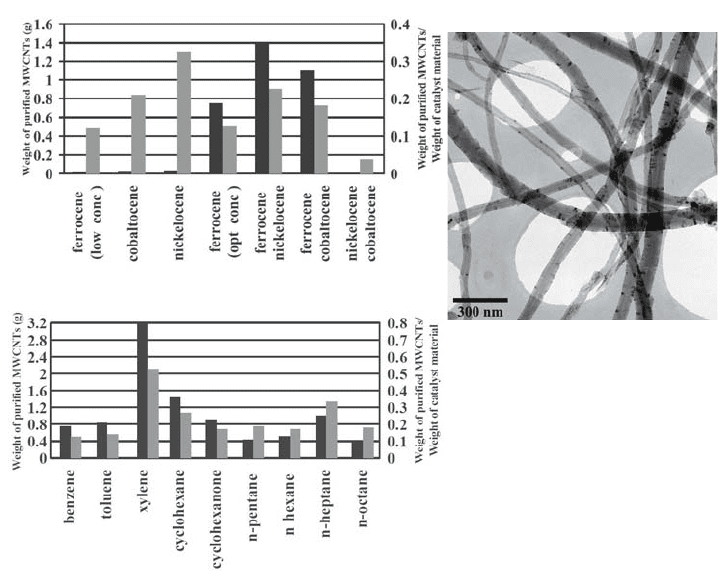
Figure 1. Left: comparison of the weight of purified carbon nanotubes produced with different
catalysts and carbon sources (black) and the weight of purified carbon nanotubes normalized to
the weight of the catalyst material (grey). Right: TEM image of MWCNTs prepared using xylene
as a carbon source.
Pure MWCNTs were grown. The MWCNTs were produced with maximum
yield when ferrocene – nickelocene catalyst mixture was used and xylene was
found to be the most efficient carbon source. For xylene, the weight of purified
carbon nanotubes normalized to the weight of catalyst material was higher than
50%.
Work supported by the Sapientia Research Programs Institute in the
framework of Fellowships 822/2001 K/513/2003.03.25, and by the MTA-MEH
Grant "Nanogas" and by OTKA through Grant nr. T043685 and M 041689.
*To whom correspondence should be addressed. Alexander Malesevic, VITO Materialen, Boeretang 200,
2400 Mol; email: alexander.malesevic@vito.be
55
V.N. Popov and P. Lambin (eds.), Carbon Nanotubes, 55–56.
© 2006 Springer. Printed in the Netherlands.
PECVD GROWTH OF CARBON NANOTUBES
ALEXANDER MALESEVIC,* A. VANHULSEL
Flemish Institute for Technological Research, Boeretang 200,
2400 Mol, Belgium
C. VAN HAESENDONCK
Solid State Physics, KULeuven, Celestijnenlaan 200 D, 3001
Heverlee, Belgium
Abstract. We report on the growth of carbon nanotubes by plasma-enhanced
chemical vapor deposition (PECVD). We used acetylene and ammonia gas
mixtures with a process pressure of 1 Torr for the growth of carbon nanotubes
on nickel layers. The metal catalyst, just a few nanometers thick, was patterned
on oxidized silicon substrates by electron beam lithography. Our aim was to
develop a cheap mass production method to grow high quality, aligned carbon
nanotubes. We used different plasma setups and scanned individual growth
parameters in order to achieve that goal. In this work, we compare the different
results obtained by direct current (DC) plasma deposition.
Keywords: carbon nanotubes; plasma-enhanced chemical vapor deposition; DC plasma
deposition; mass production
Whereas most groups concentrate on only one particular type of plasma for the
growth of carbon nanotubes, we have built a unique setup which combines DC,
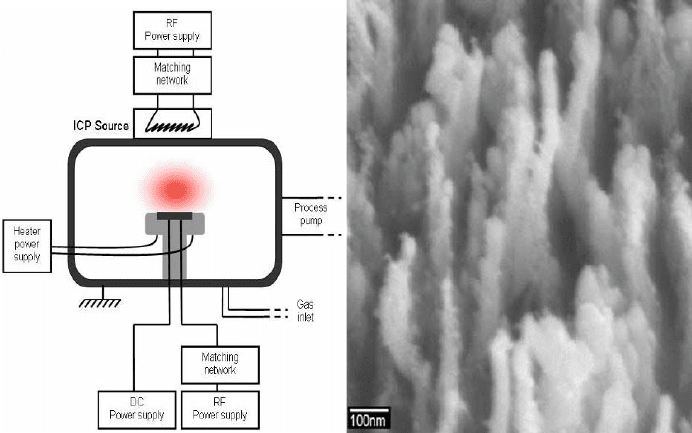
radio-frequency (RF) and inductively-coupled (ICP) plasma sources. A scheme
of the setup is drawn in Fig. 1, left. In the case of a DC or RF bias, we apply a
negative voltage to a resistively heated electrode and ignite plasma between the
electrode and the grounded reactor walls. A dense RF-ICP source can be used
in addition to or in combination with the DC or RF substrate biasing.
In order to compare the results of different types of plasma, we started to
grow carbon nanotubes with the DC plasma enhanced chemical vapor
deposition (PECVD) technique.
56
Figure 1. Left: Schematic view of a PECVD setup. Right: SEM image of carbon nanotubes
obtained with an acetylene to ammonia ratio of 25/100 sccm.
The samples consist of a 5 nm thick nickel layer that is deposited by a
conventional molecular beam epitaxy (MBE) technique on a silicon (100)
substrate with a silicon oxide buffer layer of 200 nm. The samples were placed
on the electrode and the reactor is pumped down to a base pressure of 10
-6
mBarr. The electrode was resistively heated up to 700°C in a continuous flow
of 100 sccm ammonia at 1 mBarr. The samples were annealed at 700°C during
10 minutes and afterwards pretreated in ammonia plasma of 600 V during 10
minutes. The growth was initiated by allowing the carbon containing gas,
diluted with ammonia, in the reactor for 20 minutes.
As carbonaceous gas, we used acetylene, methane, propane and butadiene in
combination with ammonia. We varied the ratio of the carbonaceous gas to
ammonia from 15/100 to 33/100 sccm. The combination acetylene with
ammonia was each time successful for the growth of carbon nanotubes,
independent of the gas ratio. A typical result is presented in Fig. 1, right.
Among the other gas mixtures, only the combination of methane with ammonia
yielded carbon nanotubes.