Popov V.N., Lambin P. (eds.) Carbon Nanotubes
Подождите немного. Документ загружается.

PREFACE
It is about 15 years that the carbon nanotubes have been discovered by Sumio
Iijima in a transmission electron microscope. Since that time, these long hollow
cylindrical carbon molecules have revealed being remarkable nanostructures for
several aspects. They are composed of just one element, Carbon, and are easily
produced by several techniques. A nanotube can bend easily but still is very
robust. The nanotubes can be manipulated and contacted to external electrodes.
Their diameter is in the nanometer range, whereas their length may exceed
several micrometers, if not several millimeters. In diameter, the nanotubes
behave like molecules with quantized energy levels, while in length, they
behave like a crystal with a continuous distribution of momenta. Depending on
its exact atomic structure, a single-wall nanotube –that is to say a nanotube
composed of just one rolled-up graphene sheet– may be either a metal or a
semiconductor. The nanotubes can carry a large electric current, they are also
good thermal conductors.
It is not surprising, then, that many applications have been proposed for the
nanotubes. At the time of writing, one of their most promising applications is
their ability to emit electrons when subjected to an external electric field.
Carbon nanotubes can do so in normal vacuum conditions with a reasonable
voltage threshold, which make them suitable for cold-cathode devices.
Nanotubes are also good candidates for the design of composite materials. They
can increase the conductivity, either electrical or thermal, of polymer matrices
which they are embedded in at a few weight percents, while improving the
mechanical resistance of the materials. Most spectacular, but still far from
industrialization, is the nanotube-based field-effect transistor. Here, a single-
wall semiconducting nanotube, contacted to two electrodes, may block or may
transmit an electric current depending on the potential applied to a gate
electrode placed at near proximity. Many other applications are foreseen,
among which nanoscopic gas sensing in which one property of the nanotube,
sensitive to adsorbed molecules, is measured. Gas selectivity may be realized
by a suitable functionalization of the nanotubes. Optical and opto-electronic
properties of single-wall nanotubes are also promising for infra-red
applications.
While the list of potential applications increases every month, the basic
properties of intrinsic nanotubes are well documented and relatively well
understood. Only relatively, because there remain several important open
issues. Many-body effects, although predicted to occur in one-dimensional
systems since a long time, are not clearly evidenced. Luttinger-liquid behavior,
xi
for instance, is not fully recognized by experiments on metallic nanotubes.
Excitons in semiconducting tubes constitute another topic of recent, sometimes
controversial debates. More important, perhaps, the synthesis and growth
mechanisms of the carbon nanotubes are not clearly pinned out. It is remarkable
that these beautiful molecules can be produced in such many different physical
and chemical conditions (electric arc discharge, catalytic chemical vapor
deposition, laser ablation ...). Partly due to that, it is still not possible at the time
of writing to produce nanotubes with all the same structure in a controllable
way. Large-scale, but detailed characterization of the nanotubes, like with any
other nanostructures, remains a great experimental challenge that will need to
be overcame.
Whether or not nanotubes will have important industrial applications is not
the essential point for the time being. What can be given for sure is that the
carbon nanotubes have triggered an intense research activity thanks to which
nanotechnology is developing so fast. The nanotubes are indeed ideal objects to
deal with in this context before other nanostructures, perhaps, will supplement
them and will open the way to real technological applications. In this book,
many aspects of the nanotubes are either touched or described in details. The
book is a snapshot, incomplete perhaps, of the state of the art at the time where
the ASI took place, on the shore of the Black Sea.
We gratefully acknowledge the generous support from the NATO Scientific
and Environmental Affairs Division and the University of Namur. We thank all
authors for preparing high-quality manuscripts.
V. N. Popov Ph. Lambin
Sofia Namur
Bulgaria Belgium
November 2005
xii
ORGANIZING COMMITTEE
Co-Director
Prof. Philippe Lambin
Département de Physique
Facultés Universitaires Notre-Dame de la Paix
Namur, BELGIUM
Co-Director
Prof. Valentin Popov
Faculty of Physics
University of Sofia
Sofia, BULGARIA
Scientific Chairman
Prof. Hans Kuzmany
Universität Wien
Institut für Materialphysik
Wien, AUSTRIA
Scientific Advisor
Prof. Angel Rubio
Dpto. Fisica de Materiales
Facultad de Quimicas U. Pais Vasco
San Sebastian/Donostia, SPAIN
Scientific Advisor
Prof. Minko Balkanski
Université Pierre et Marie Curie
Paris, FRANCE
xiii
Part I. Synthesis and structural characterization
*To whom correspondence should be addressed. Björn Hornbostel; e-mail: b.hornbostel@fkf.mpg.de
1
V.N. Popov and P. Lambin (eds.), Carbon Nanotubes, 1–18.
© 2006 Springer. Printed in the Netherlands.
ARC DISCHARGE AND LASER ABLATION SYNTHESIS OF SINGLE-
WALLED CARBON NANOTUBES
BJÖRN HORNBOSTEL,* MIRO HALUSKA, JIRKA CECH,
URSULA DETTLAFF, SIEGMAR ROTH
Max-Planck-Institute for Solid-State Research, Stuttgart,
Germany
Abstract. The laser ablation synthesis of carbon nanotubes is contrasted with
the arc discharge method with respect to the synthesis product. A novel
combination of two laser systems of different wavelengths for the laser ablation
synthesis is presented. The impact of sulfur on the synthesis process is
discussed. An excerpt of our quality control protocol is presented.
Keywords: single-walled carbon nanotubes; laser ablation; arc discharge; synthesis;
CO
2
; Nd:YAG; sulfur; quality control protocol
1. Introduction
The prospects for a wide range of applications of single-walled carbon
nanotubes (SWCNT, SWNT) rely on the development of a cost-effective large-
scale production. The three main roots for SWNT synthesis are laser ablation
(LA), arc-discharge (arcD)
1-3
in a Krätschmer
4
reactor, and chemical vapor
deposition (CVD). Besides these, there are plenty of scions where different
methods merge into each other, other ambient conditions are used (e.g.,
submerged arcD
5-8
) or where other supporting energy sources sustain (e.g. PE-
CVD
9-12
). Here, only the laser ablation and the standard Krätschmer arc
discharge method are regarded. These two synthesis methods in plasma
aggregate state rely on the presence of a catalyst for the production of SWNT.
Historically, the arcD method was the first technique for multi-walled
carbon nanotubes
1
(MWCNT, MWNT) and single-walled carbon nanotubes.
2,3
By this method one is able to produce roughly 100 mg/min of SWNT-
containing soot. However, due to highly fluctuating conditions in the plasma
2
plume of the light arc it is difficult to keep a favorable condition for a long
period. There are attempts to keep the conditions stable, which is essential for
the production of flawless nanotubes at a high yield. Biggest drawback of the
Krätschmer method is the relative high amount of undesired by-products, as
fullerenes, graphite and amorphous carbon (a-C).
In 1995 Guo et al.
13
synthesized nanotubes by laser ablation for the first
time. The usage of concentrated light directed on a target to evaporate material
and to create highly reactive plasma is a mean to engender more controlled
conditions in the plume. In the following we will present our way to synthesize
SWCNT by ArcD and LA. Therefore, we will recapitulate the state of the art
and our own experiences with both methods. Firstly, we will elaborate on the
technical equipment and parameters. Later we will describe briefly how we
evaluate as-produced and purified SWCNT material by our quality control
protocol.
2. Technology and experimental
2.1. DC ARC DISCHARGE TECHNOLOGY
Between a pair of graphite electrodes in an inert gas atmosphere a DC electric
arc discharge is ignited by e.g. a short contact between both. As a result,
electrons exit from the cathode and form an electron cloud. At this time the
voltage is still zero. As dissociating both from each other the resulting empty
space between them is filled up by electrons and by the ambient gas. The
electrons are accelerated towards the anode and on their way they ionize the gas
molecules cascade-like by impact ionization. Positive charge carriers move to
the negative counter pole. As soon as enough charge carriers are situated in the
conducting channel, the arc ignites. At the moment of electrode separation the
voltage source has to deliver full voltage. The incoming electrons give up their
kinetic energy to the anode which causes the material to sublimate. The cathode
will be cooled by discharge work of the electrons. The electrodes are typically
water-cooled graphite rods separated by few mm. A bias voltage of 15 to 35V is
applied at currents between 50 and 120A.
Achieving stable discharge plasma is the main factor in generating an
environment favorable to nanotube growth. This is not so easy, as the anode is
consumed and therefore has to be tracked towards the cathode continuously.
Furthermore, the stability of an electric arc is limited due to its moving nature
on the cathode and anode surface. Additionally, after already a few minutes the
resulting uneven consumption of the anode and build-up of material on the
cathode side causes a further instability in the DC arc. The rate of synthesis of a
lab Krätschmer reactor can surpass 100 mg/min.
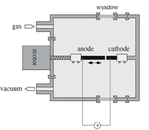
3
Figure 1. Schematic of a standard DC Krätschmer reactor (arc discharge).
A vast amount of studies on the fundamental technical parameters to
optimize the arcD method has been accomplished and people are still working
on it. Apparently, the yield and the properties of the nanotubes are not just
dependent on the anode composition, the background gas pressure, the gas
composition, ... but also linked to the apparatus size and its geometry, the
thermal gradients and other influences of the sublimation system. Due to
sometimes total different results (yields) at same parameter sets in different
reactors it is hard to deduce a general rule for an optimized production.
2.2. ARC DISCHARGE PARAMETERS
The catalysts can be introduced by either drilling a hole into the anode or filling
it up with a catalyst-carbon mixure or by intermixing a larger portion of C and
catalyst and then pressing to a rod. As for the laser ablation (LA) it was found
that using bi-material plus C mixtures of Co, Ni, Y, and Fe favors the
production of larger quantities of SWNT. Furthermore, people agree upon Co/Y
and Ni/Y intermixtures being the most effcient. Recently, Itkis et al.
14
published
their results on optimum anode compositions.
Helium at around 500-800 mbar is most favorable for the SWCNT-
production. Additional gases (e.g. H
2
) or substances (e.g. S) are able to
influence the yield, the diameter distribution and the quality of the product. We
currently exploit the advantage of sulfur in the process.
4
In the arc discharge production method sulfur functions as a SWNTs growth
promoter and surfactant when added together with Ni/Fe/Co,
15
Ni/Co,
15,16
Ni/Y/Fe or Ni/Ce/Fe
17
catalysts into the anode. Sulfur is used as promoter in
other nanotube production methods as well, like in the solar energy evaporation
method
18
with Ni/Co and in the laser vaporization method
19
with Ni/Co/Fe. It
was found that sulfur alone without metal catalysts does not catalyze the
SWNTs growth process.
20
Typically for all methods mentioned and all catalysts used, the addition of
sulfur increases the yield of nanotubes and broadens the tube diameter
distribution to extend out to 6 nm. Exception is the formation of nanotubes with
small diameters in the range of 0.9-1.1 nm as reported by Alvarez et al.
18
Our work is focused on the influence of the S concentration added to Fe/Y
catalysts on the yield of nanotubes and their properties. We chose Fe instead of
Ni because it is much easier to remove it from the arc product. Our primary aim
is to find satisfactorily high yields of high quality SWNT web material. One of
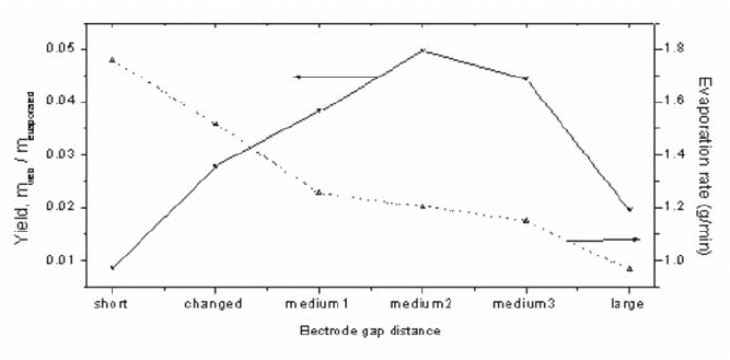
the growth controlling parameters is the distance of the electrodes during the
arc process. It influences the evaporation rate (temperature of anode) and the
yield of web product. The highest the yield was obtained for the distance ~ 2
mm. The anode evaporation rate was 1.2 g/min.
Figure 2. The yield and the evaporation rate dependences on the electrode gap distance.
As it was discussed in the above mentioned publications sulfur does not
dissolve in the bulk of the transition metals but adsorbs on the surface. The
metal-sulfur interactions change surface tension and melting point of small
droplets of metals. This can support the creation of SWNTs for metals which in
pure form catalyze badly. The overcritical concentration of S has a poisoning
effect on SWNTs growth similar as for many other catalytically controlled
processes. The highest yield of web product containing the smallest
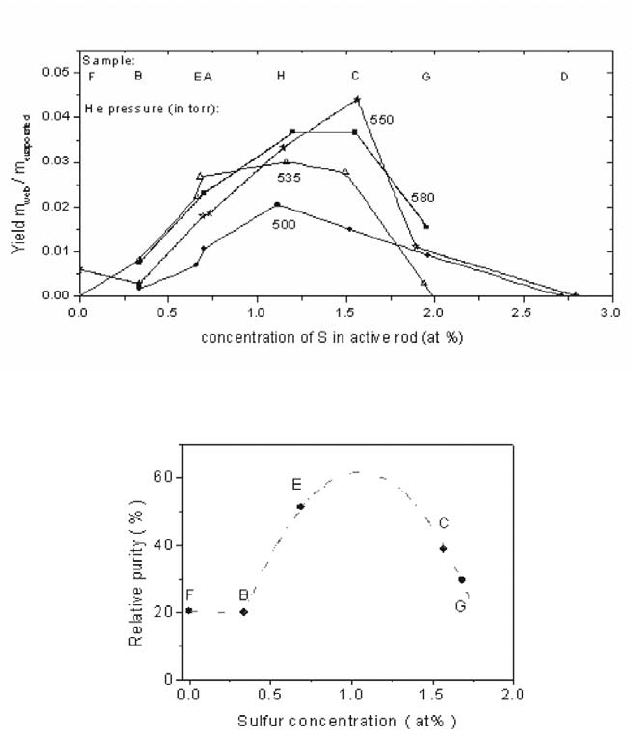
5
concentration of metals was obtained for the sample C where the composition
of the anode is Fe:Y:S:C 6.6 at.%:1.1 at.%:1.6 at.%:90.7 at.%. A more detailed
overview on this work is presented in.
21
Figure 3. The yield dependence over the concentration of sulfur.
Figure 4. The relative purity determined by NIR-spectroscopy.
13,14
A dashed line depicts the
trend. Sulfur was used to attain better results. The background pressure was 550mbar.
2.3. LASER ABLATION TECHNOLOGY
The standard SWNT growth setup consists of a quartz tube (~25 mm diameter,
1000-1500mm length) mounted inside a hinged tube furnace that can operate at
a temperature of 1200°C. The quartz tube is sealed to vacuum components. The
laser beam enters the quartz tube through a Brewster window, which should be
6
plated by some anti-reflex layer for the incoming beam. Inert gas, e.g., Argon,
or mixed gas compositions are introduced at the upstream side of the tube. The
gas feeding is controlled by a mass flow controller and the pressure by a
preassure controller downstream. Before the gas exits the system it passes a
water-cooled brass collector and a filter to collect the SWNTs. The brass
collector is inserted into the quartz tube and positioned just outside the furnace.
A rotating rod is led through the water-cooled collector. A target consisting of
carbon and metall catalysts is attached to it. This is to ensure a more
homogenious ablation of the target. In addition it is appropriate to have the laser
beam scanning over the target. The carrier gas-flow sweeps most of the carbon
species produced by the laser evaporation out of the furnace zone depositing it
as soot on a water-cooled copper rod. Usually the ablation laser is a Nd:YAG
opperating at 1064 nm or 532 nm, respectively. Specific values of those
Nd:YAG systems are between 300 mJ and 1.5 J per pulse at <10 ns FWHM.
The beam is usually focused to a 3-8 mm diameter spot.
A different approch for laser synthesis of SWCNT is the exertion of CO
2
-
laser.
21-25
Here, laser ablation at 10.6 Pm, with 250W and a spot size of 0.8-
1mm produces a notable quantity of carbon nanotubes. Maser et al.
26
reported a
maximum ablation rate of 200 mg/h. In case of a pure CO
2
-laser process a
furnace is not inevitably necessary. The energy for the evaporation of the targert
can be delivered completely by the beam itself. Maser et al.
26
found no big
difference betweeen Nd:YAG and CO
2
-laser systems concerning yields and
structural characteristics of the produced SWNT. However, they consider the
scaling-up possibility of CO
2
-laser systems to be easier by far.
The fundamental limitation which is inherent to today’s laser ablation
systems is their restriction of milligram-quantity per day. This is far too low to
sustain more than laboratory-scale levels of development. Thess et al.
27
reported
optimization of a Nd:YAG-Laser ablation process. The initial laser pulse (532
nm, 250 mJ, 10 Hz, 5 mm diameter spot) was followed 50 ns later by a second
pulse (1064 nm, 300 mJ, 10 Hz, in a 7 mm diameter spot coaxial with the first
laser spot). This provides a more uniform evaporation of the target resulting in
increased SWNT yields. They used a 25mm-diameter quartz tube. Since the
SWNT production rate of this laser-oven set-up was only 80 mg/day, Rinzler et
al.
28
scaled it up by more powerful laser systems. They found that the
generation of material containing more than 50 vol.% SWNTs requires a
geometry which mimics the original 25mm-diameter tube. They added a 25mm-
diameter quartz tube coaxial with the 50mm-tube extending from 4 mm ahead
of the graphite target. The SWNT yield soared up 90 vol.% and an amount of
1g/day carbonaceous nano-material could be synthesized. This configuration of
the set-up enables the evaporation plume to be lifted off from the target and to