Pavlidis I. (ed.) Human-Computer Interaction
Подождите немного. Документ загружается.

4
Sketch-Based Interfaces for Parametric
Modelling
Ferran Naya, Manuel Contero & Nuria Aleixos
Universidad Politécnica de Valencia
Spain
Joaquim A. Jorge
INESC-ID & Universidade Técnica de Lisboa
Portugal
Pedro Company
Universidad Jaume I
Spain
1. Introduction
Sketching is still widely used by designers and engineers as it continues to be a useful and
powerful tool that helps designers during the conception of a new product (Tversky, 2002).
If engineers and designers generally use sketches the question is, why sketching is not
integrated in the digital design process? Available Graphical User Interfaces (GUI) for CAD
applications are still by and large constrained by the WIMP (Windows, Icons, Menus and
Pointing) paradigm and current commercial CAD systems not support sketch-based design.
Therefore, the problem is that the sketches continue to be unplugged to the rest of the
design process. In other words, in spite of recent advances in Computer Aided Design,
current CAD tools are not well suited to the initial design stages of product development,
because many techniques and idioms characteristic of hand-made drawings cannot be used
directly in CAD systems. To sum up, there is a disconnection between sketching and CAD
tools in the new product development process and true Computer-aided Sketching (CASk)
tools are required.
During last decades different research lines have been explored to improve the human-
computer interface in CAD systems. In this context, some CASk systems have been
developed to support freehand drawings as a way to create and edit three-dimensional
geometric models. These advanced CASk systems try to provide more functionality than
paper or a whiteboard, giving an added value to sketching on a digital environment. This
extra functionality usually has been directed either to improve the graphic quality of the
sketch by means of a beautification process or it has been oriented to automatically
transform the 2D sketch into a 3D model. Interest in CASk systems has increased in the last
years as new hardware devices such as Tablet-PCs and LCD graphics tablets have been
launched to the market.

Human-Computer Interaction
44
In this chapter we show our main contributions in the field of computer aided sketching.
The aim of this work is to explore new interaction paradigms in CASk tools, geared at
exploiting sketching skills of designers and engineers. Through this chapter the GEGROSS
application developed by our research group (www.regeo.uji.es) will be used to illustrate
the important concepts. GEGROSS is a CASk application than performs an online
conversion of a raw sketch into a 3D model supporting parametric control of geometry.
2. Sketch Based Interfaces and Modelling (SBIM)
Over the last decades different research lines have been explored to improve the human-
computer interface in CAD systems. One of these new approaches is termed as “Sketch-
based interfaces and modelling” (SBIM) that is an emerging research field oriented to the
creation of new computer tools to promote a shift (Igarashi & Zeleznik, 2007) to a new
paradigm where sketches would be used as input to create 3D digital engineering models.
Recent advances in SBIM applications promise better integration of sketching and CAD
tools, integrating a paradigm shift to change the way geometric modelling applications are
built, in order to focus on user-centric systems, rather than systems that are organized
around the details of geometry representation. While most of the activity in this area in the
past has been focused in off-line algorithms, where an application analyzes a complete
sketch and then proposes a plausible 3D model, the growing focus on sketches and
modelling has brought forth a new emphasis on approaches geared towards interactive
applications. These interactive applications interpret in real time the input generated by a
digitizing tablet and a pen, an approach also termed calligraphic interface (see Computers &
Graphics vol. 24, special issue “Calligraphic Interfaces: towards a new generation of
interactive systems”). This kind of interface relies on the analysis of the pen strokes
generated by the user, and exploits the space-time information provided by those to yield
richer and more expressive interaction. A common feature of these systems is to use
gestures (a special graphic symbol or stroke sequence) as commands (Fonseca and Jorge,
2001). These interfaces are specially suited to applications requiring capturing rough shapes
and ideas, usually associated to the conceptual design stages of new product development.
In these interfaces the artificial dialogue constraints imposed by the previous generation of
WIMP user interfaces are removed and designers can interact with the computer in ways
evocative of more traditional media, such as paper and pencil.
To sum up, there is a growing research interest in using freehand interaction and sketches as
a way to create more natural interfaces, especially for the creation and edition of three-
dimensional geometric models. Digital sketching can offer an added value with respect to
paper-and-pencil sketching, exploiting a more “natural” environment that does not disturb
the user while he is creating the drawing. The availability of proper hardware as Tablet-PCs,
electronic whiteboards and other devices supporting touch or stylus input is other of the
reasons that support growing interest in this kind of interfaces.
The main requirement for designing an advanced CASk system should be to provide more
functionality than paper or a whiteboard, trying to give an augmented digital paper. This
extra capability with respect plain paper in some cases has been oriented to improve the
graphic quality of the sketch by means of a beautification process as mentioned previously,
or it has been oriented to automatically transform the 2D sketch into a 3D model. Here, it is
possible to distinguish two principal approaches to transform the 2D sketch into a 3D
Sketch-Based Interfaces for Parametric Modelling
45
model. One method relies on gesture alphabets as commands for generating objects from
sketches (a gesture in this context represents a graphical symbol that is translated into a
command). Examples of gestural systems are SKETCH (Zeleznik et al., 1996), Teddy
(Igarashi et al., 1999), GIDeS (Pereira et al., 2000) and Blobmaker (De Araujo & Jorge, 2003).
Gestural systems provide predefined gesture alphabets that encode some geometric
modelling operations; basically these systems substitute the selection of icons and menus by
graphic gestures. The second approach, derived from computer vision, uses algorithms to
reconstruct geometric objects from sketches that depict their two-dimensional projection.
Examples of reconstruction systems are Stilton (Schweikardt & Gross, 2000), Digital Clay
(Turner et al., 2000) and CIGRO (Contero et al., 2005).
In summary, two basic alternatives exist to create 3D models from sketches: reconstruction
based and gesture based. From these approaches the reconstruction based is the most
transparent to users, since they have only to create a sketch which does not require a priori
knowledge of a gestural command set. Chronologically, reconstruction systems appeared
before gestural ones, because reconstruction systems took advantage of previous work in
offline line drawing recognition. On the other hand, gestural systems require more elaborate
recognition engines for distinguishing geometry information from gestural codes and most
importantly, must provide elaborate user feedback in real time. Partly due to this and
because of the restricted computing power available in earlier tablet PCs, some early
systems avoided the disambiguation step by using icons and menus to explicitly provide
this information to the system.
3. The GEGROSS application
The REGEO research group has developed in recent years the GEGROSS system, which is a
CASk interactive application that converts raw sketches to three-dimensional models. The
GEGROSS application follows the gestural approach and allows the user to generate three-
dimensional models using some gestural commands. In this system, it is possible to draw
two-dimensional parametric freehand sections combined with the use of a simple gesture
alphabet that encode some geometric modelling operations.
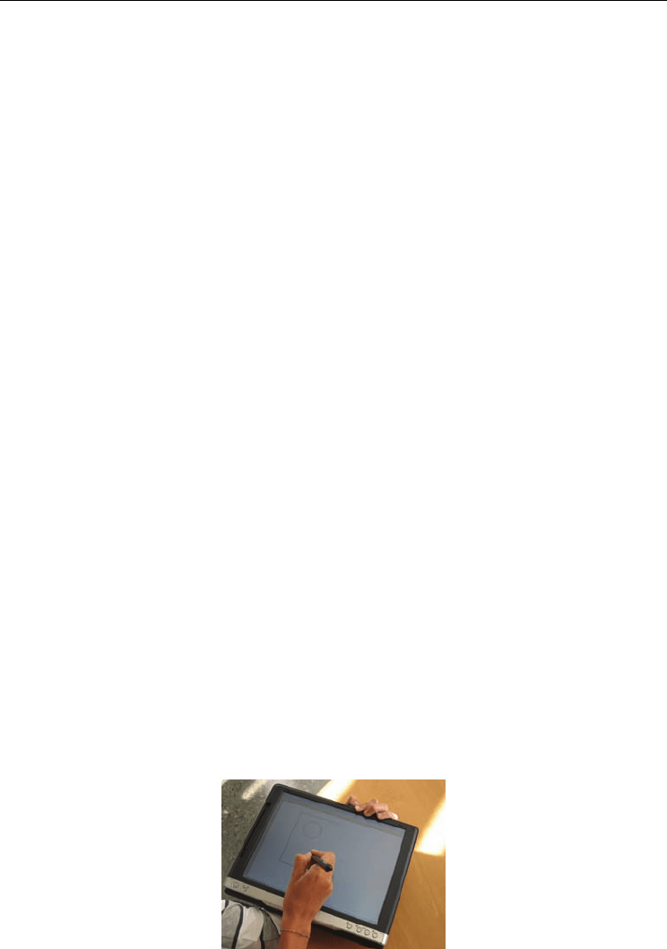
As can be seen in Fig. 1, in this application, the user introduces the freehand sketch directly
onto a Tablet PC, using a reduced-instruction set calligraphic interface. The design goal of
this interface is to create two-dimensional parametric sections and three-dimensional
models in a very simple way, using the conventions of technical drawing to define the shape
of the section. The user interface is designed to minimize the interaction with menus or
icons in an attempt to emulate the traditional use of pen and paper.
Fig. 1. User stroke input on a Tablet PC (GEGROSS)
Human-Computer Interaction
46
In the design of this system some assumptions have been taken to simplify the recognition
process to interpret gestures. The main assumption is that the final user of this system will
have a technical or engineering background. That means that users know the conventions of
technical drawing, and the application is designed to recognize the typical drawing
procedures that designers/engineers follow to create a technical sketch.
The gestural modelling process is organized in two stages. In first place a 2D profile is
defined. To do this, the user introduces the geometry of the 2D section using a two-
dimensional parametric freehand sketch module called ParSketch (Naya et al., 2007). This
module offers many of the features provided by current commercial parametric CAD
applications as it is built on top of the most common parametric engine of the market
(D-Cubed components from the SIEMENS firm, www.plm.automation.siemens.com). Later,
in the second stage and also using gestures, it is possible to make an extrusion or a
revolution of the parametric section generated in the previous stage to create a 3D solid
model. Then this process, the user can continue sketching new 2D sections onto the faces of
the generated object and applying the corresponding modelling gestures.
The ParSketch module implements a calligraphic interface to manage the geometric entities
and the geometric constraints found in two-dimensional sections. The system distinguishes
two modes of operation: one where the strokes made by the user are interpreted as
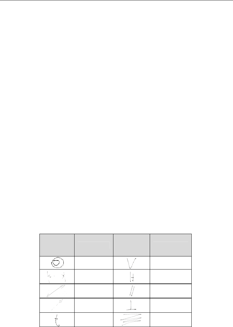
geometric entities and other where the strokes are considered as commands. In table 1 the
supported gestural alphabet is presented. Majority of gestures are inspired in the typical
symbols used in technical drawing. When the user introduces a new stroke, ParSketch uses
the drawing pressure as a mode discriminator (geometry or gesture). Then, the application
interprets the type of stroke drawn by the user using a geometry recognizer (RecoGeo) or a
gestural recognizer (RecoGes). Next, an automatic beautification stage is executed
transforming the strokes in the corresponding geometry entities and constraint symbols.
The geometric recognizer RecoGeo supports complex strokes that after interpretation are
split into its constituent primitives, allowing users to build simple sketches composed by
line segments and arcs, which are automatically tidied and beautified. The application
cleans up input data and adjusts edges to make sure they meet precisely at common
endpoints in order to obtain geometrically consistent figures by filtering all defects and
errors of the initial sketches that are inherent to their inaccurate and incomplete nature.
Constraint
gestures
Class
Constraint
gestures
Class
Concentric
Vertical
Linea
dimension
Horizontal
Diametral
dimension
Parallel
Radial
dimension
Perpendicular
Tangent
Cross-out
(erase)
Table 1. Gesture alphabet for constraining 2D geometry implemented in ParSketch

Sketch-Based Interfaces for Parametric Modelling
47
Once the designer has introduced the complete outlined sketch, it can be edited,
dimensioned and constrained using the gesture recognizer RecoGes. RecoGes has been
developed to provide an alphabet of geometric/dimensional constraints to parameterise the
sketches. In other words, if user wants to generate design alternatives, or adjusting some
sketch to reach some dimensional condition, the system provides parametric capabilities
and handwritten dimensional control to the two-dimensional freehand sections.
Handwritten number recognition is provided by the Windows XP Tablet PC Edition
operative system.
As explained before, the mode detection has been solved using the electronic pen pressure
information, since the system is intended to be used by persons with basic engineering
drawing skills. It can be said that line width is the mode-change feature when reading an
engineering drawing. The usual practice is that thick lines are associated to geometry and
thin lines to dimensions and other type of annotations. As line width is related to increasing
pressure with the pencil while drawing, this information is used to discriminate among
geometry or gesture. In other words, drawing making high pressure on the screen is
intended for geometry input, while soft pressure is associated to auxiliary information. The
user can configure a pressure level threshold to classify strokes as geometry or gestures.
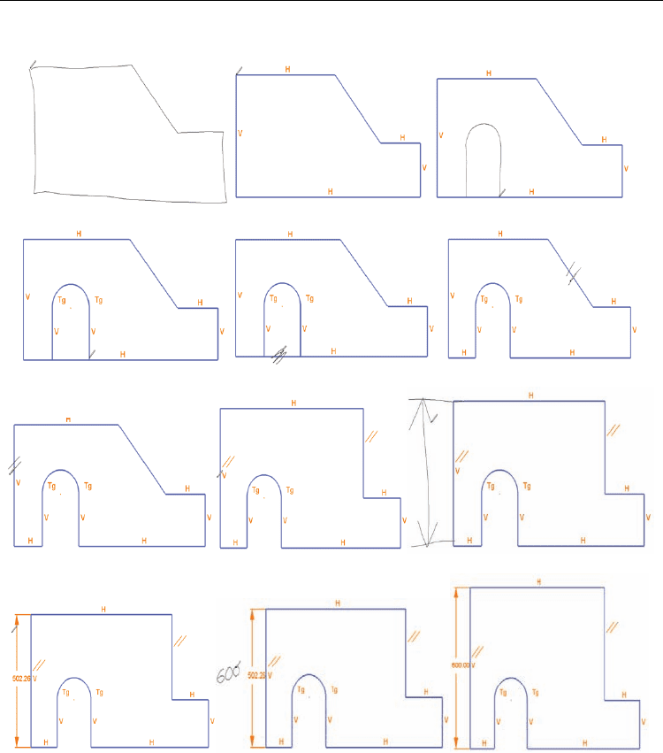
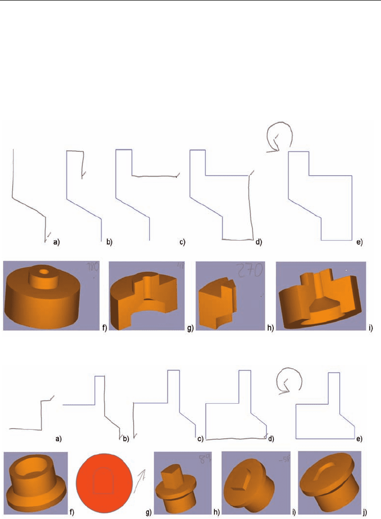
An example of interaction with ParSketch is presented in Fig. 2. In this example the user
draws the whole contour in 2.a. One single stroke is accepted as input, and it is later
decomposed by the application into six rectilinear and connected strokes. When the
application shows the beautified version (Fig. 2.b), the user adds another complex stroke
composed by two segments and one arc. The geometry is then beautified (Fig. 2.d). In Fig.
2.e we can see the use of the scratching gesture to refine the geometry. Drawing this gesture
is interpreted by the application as a command to delete those geometric entities intersecting
the smallest quadrilateral that encloses the gesture. Then a parallel constraint is applied by
simply sketching its associated gesture over the two segments we want to make parallel (see
2.f, 2.g, 2.h). Once the desired shape has been obtained, we can proceed with dimensional
control. A first action is to draw a dimension without the dimension text (see Fig. 2.i). This is
interpreted by the application as a measure command, and the current value of that
dimension is shown, as seen in Fig. 2.j. If the user wants to change the current dimension
value, he or she writes the new value next to the current one. Then the system regenerates
and displays the new geometry (Fig. 2.k and 2.l). In this way, the system provides a very
natural form of imposing the desired dimensions over the sketch.
As can be seen, once the designer has introduced the complete outlined sketch, it can be
edited, dimensioned and constrained. In other words, the interface offers some innovative
ways of controlling the shape after a beautified constrained model is presented to the user.
The application manages two types of constraints and dimensions: “automatic” and “user
defined”. Automatic constraints and dimensions are those provided by the system. The
“user defined” ones are sketched by user. As can be seen in Fig. 2, the user can add new
constraints drawing their associated gestures (Table 1) near the geometric entities where
they must be applied. These gestures can be written by the user to impose some desired
constraint. In this context, the scratch gesture can be used to remove undesired constraints.
The automatic beautification process (automatic constraints and dimensions) is in charge of
adjusting the input sketch in real time and provides an immediate feedback to the user,
because it operates as the user draws the sketch.
Human-Computer Interaction
48
a) b) c)
d) e) f)
g) h) i)
j) k) l)
Fig. 2. Sketching sequence in ParSketch
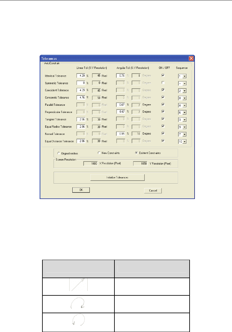
The user can configure how the parametric engine controls the geometry. This control is
implemented by a set of threshold values used to decide whether a geometric constraint is
verified (see Fig. 3 for details) or not. The user has the possibility of enabling or disabling a
specific constraint by an on/off selection box. Also it is possible to establish the order in
which the constraints will be applied, using the “sequence” field in the dialog box presented
in Fig. 3. These tolerance settings are intended to provide a tool for controlling the
Sketch-Based Interfaces for Parametric Modelling
49
beautification action. Some of the supported constraints are: coincident (if a coincident
constraint is defined between a point and any geometry then this implies that the point lies
on the geometry), concentric, parallel, tangent, equal radius (it implies that the radii of the
geometries are the same), perpendicular, equal distance (this constraint is used for search
geometries with the same length), distance, angle and radius.
Fig. 3. Tolerance settings
Once a two dimensional section has been defined with the ParSketch module it is possible,
using gestures, to make an extrusion or a revolution of the parametric section to create a 3D
model. Then this process can continue sketching new 2D sections onto the faces of the
generated object and applying the corresponding modelling gestures. In this second stage
the command set includes the three gestures listed in Table 2.
Modeling gestures Class
Extrusion
Revolve-right
Revolve-left
Table 2. Gesture alphabet for modelling operations implemented in GEGROSS
Human-Computer Interaction
50
The application recognizes the type of stroke drawn by the user using the gestural
recognizer (RecoGes). Fig. 4, Fig. 5 and Fig. 6 show examples of modelling with the
GEGROSS application.
The system uses the geometric kernel ACIS (www.spatial.com) to store the geometric
entities. The points of the stroke are taken by means of the Wintab API
(www.pointing.com), which is an open interface that directly collects pointing input from a
digitizing tablet and passes it to applications. This API allows retrieving additional
information as the pressure the user applies at each point of the stroke over the tablet.
Fig. 4. Modelling sequence in GEGROSS. Example of revolution shape
Fig. 5. Modelling sequence in GEGROSS. Example combining revolution and extrusion
Sketch-Based Interfaces for Parametric Modelling
51
4. Sketching-Based vs. WIMP Interfaces for Parametric Drawing
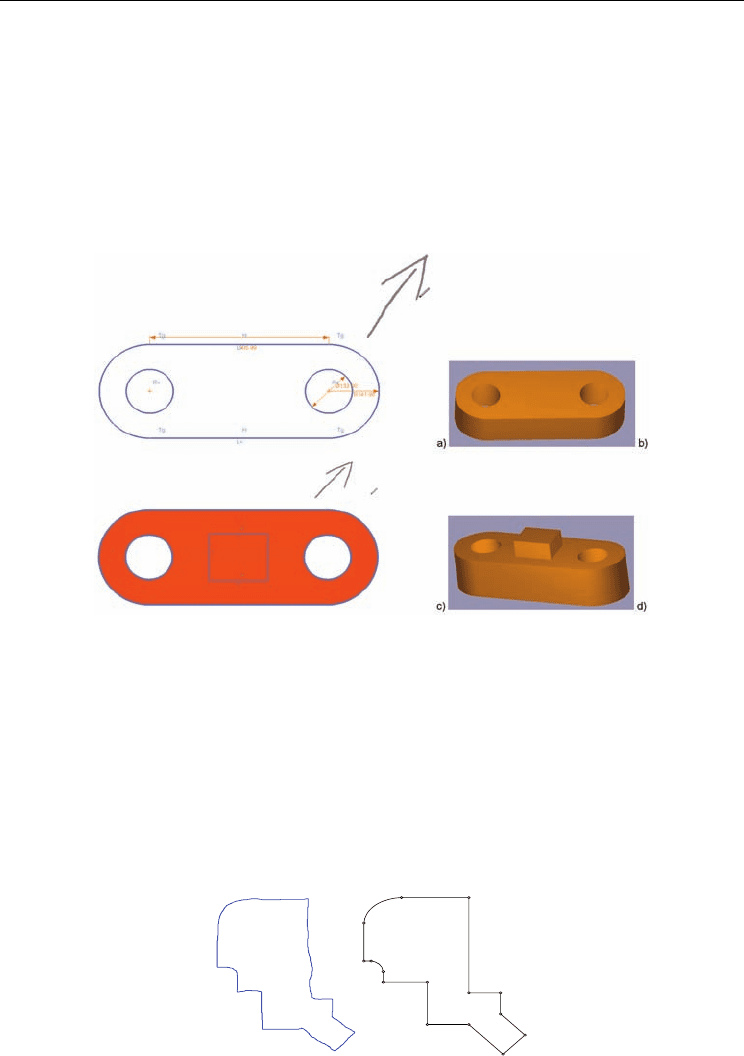
From a theoretical point of view we can show that if the sketching application supports
complex strokes, i.e. strokes composed by several basic primitives as line segments and arcs
(see Fig. 7 as an example) this means a potential advantage over WIMP interaction. For
instance, analyzing sections composed exclusively by arcs and line segments, we can make
an approximated calculation of the number of interactions required by a WIMP application
to complete the drawing task.
Fig. 6. Modelling sequence in GEGROSS. Example of extrusion-modelled shape
Usually one interaction is required to initiate the drawing process (one mouse click) and
another one for finishing (a double click or pressing the enter key, for example). For drawing
the line segments and tangent arcs in Fig. 7 two more interactions per elements are required:
one is for defining the connecting vertex and the other for the selection of the proper
geometric constraint as the horizontal, vertical, perpendicular or tangent conditions in this
example. We count for this second interaction although, in modern parametric sketchers,
geometric constraints are dynamically added as the user moves the drawing cursor. Only
after the user detects the proper constraint is when he/she introduces the next entity vertex.
This requires user attention, so we add it to the global number of interactions.
Fig. 7. Automatic segmentation vs. explicit drawing

Human-Computer Interaction
52
The last term in the calculation of total number of interactions is related to primitive
switching operation. When the user wants to link for example a tangent arc to a previous
polyline, he/she must spend one interaction, providing this information to the system
(using for example a contextual menu or icon selection), and then spend a second interaction
to come back to polyline mode.
In sum, if n
l
and n
a
represents the number of line segments and arcs respectively, the total
number of interactions N spent by the user is:
N =2 + 2(n
l
+ n
a
) + 2n
a
(1)
Even for not too complex figures (N= 36 in figure 4) the last equation shows that although a
user could employ several strokes to complete the shape and require some corrections to
overcome recognition errors by the sketching application, there is a wide margin to compete
with WIMP-based interaction in terms of efficiency. So it is feasible to implement a robust
geometric segmentation and recognition to keep advantage over WIMP interaction. We
think that this is one of the keys for success in providing a real alternative or at least a
complement to a WIMP interface. But as Igarashi and Zeleznik noted (Igarashi & Zeleznik,
2007), we must adapt the design of our applications to exploit the pen’s intrinsic capacity for
rapid, direct, modeless and expressive 2D input.
To improve segmentation results, our system can be adapted to each user way of sketching
by means of a tolerance control panel previously described (see Fig. 3) that defines some key
parameters for improving recognition. As explained before, the mode detection has been
solved using the electronic pen pressure information, since GEGROSS is intended to be used
by persons with basic engineering drawing skills.
In relation with other typical operations in a parametric 2D application, as imposing
geometric constraints or performing dimensional control, the number of interactions
required by both systems is similar. So we can conclude that from the efficiency point of
view the sketch based approach is a viable option.
4.1 Usability Study
The usability of digital thinking sketches as opposed to traditional paper-and-pencil
sketches was measured elsewhere (Company et al., 2006). In this analysis, we have centred
our study in the user satisfaction component of usability (Hornbæk, 2006), following the
usability definition provided by ISO 9241-11, where it stands for “extent to which a product
can be used by specified users to achieve specified goals with effectiveness, efficiency and
satisfaction in a specified context of use”.
As noted previously, the main design goals of the GEGROSS application are:
• Expeditious creation of shapes composed by polylines, arcs, and circles.
• Dimensional and geometric shape-control though the use of technical drawing
conventions.
The evaluation involved six CAD instructors and six students with parametric CAD
experience. All but one of the CAD instructors were male with an average age of 55. All
students were male with an average age of 24.
We allowed 30 minutes for the evaluation, which had four parts: an overview of the system
where some short videos showed the system operation, an instruction stage with a modified