Munson B.R. Fundamentals of Fluid Mechanics
Подождите немного. Документ загружается.

In such situations boiling occurs 1though the temperature need not be high2, vapor bubbles form,
and then they collapse as the fluid moves into a region of higher pressure 1lower velocity2. This process
can produce dynamic effects 1imploding2that cause very large pressure transients in the vicinity of the
bubbles. Pressures as large as 100,000 psi 1690 MPa2are believed to occur. If the bubbles collapse close
to a physical boundary they can, over a period of time, cause damage to the surface in the cavitation
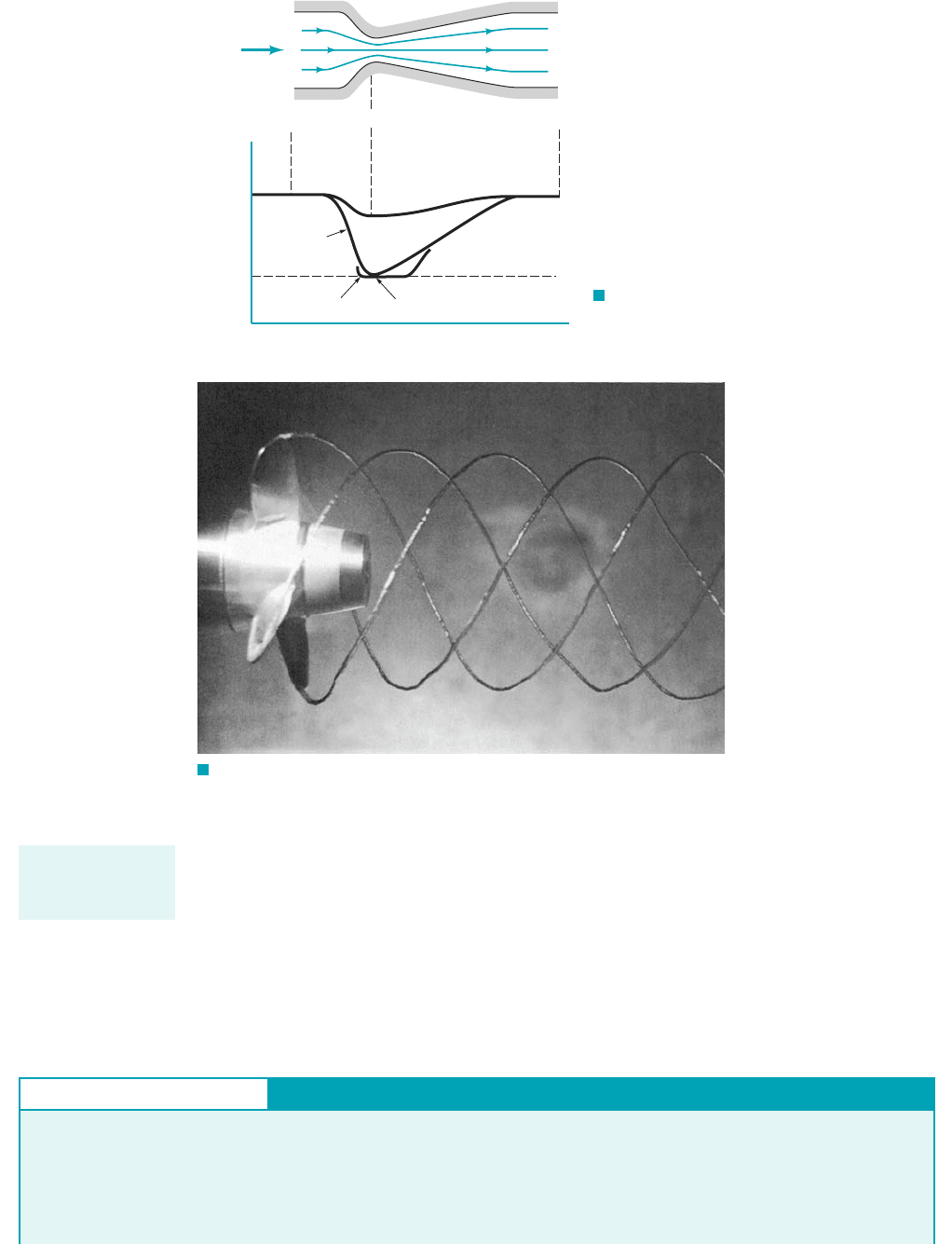
area. Tip cavitation from a propeller is shown in Fig. 3.17. In this case the high-speed rotation of the
propeller produced a corresponding low pressure on the propeller. Obviously, proper design and
use of equipment are needed to eliminate cavitation damage.
3.6 Examples of Use of the Bernoulli Equation 117
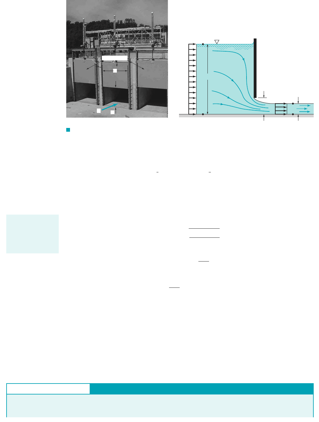
F I G U R E 3.16 Pressure
variation and cavitation in a variable
area pipe.
Q
p
(Absolute
pressure)
(1)
(2)
(3)
Small Q
Moderate Q
Large Q
Incipient cavitation
p
v
0
x
Cavitation can
cause damage to
equipment.
F I G U R E 3.17 Tip cavitation from a propeller. (Photograph
courtesy of Garfield Thomas Water Tunnel, Pennsylvania State University.)
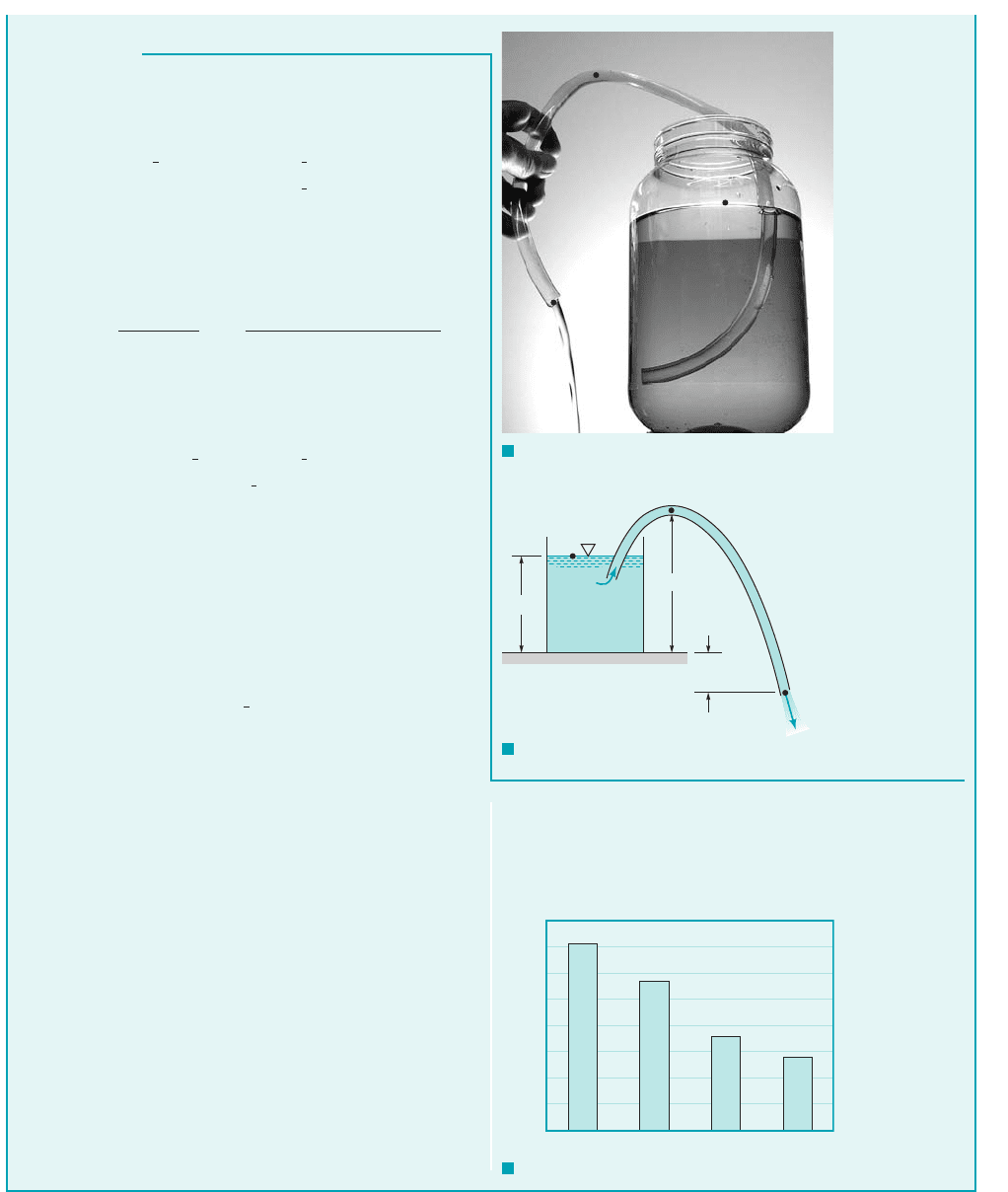
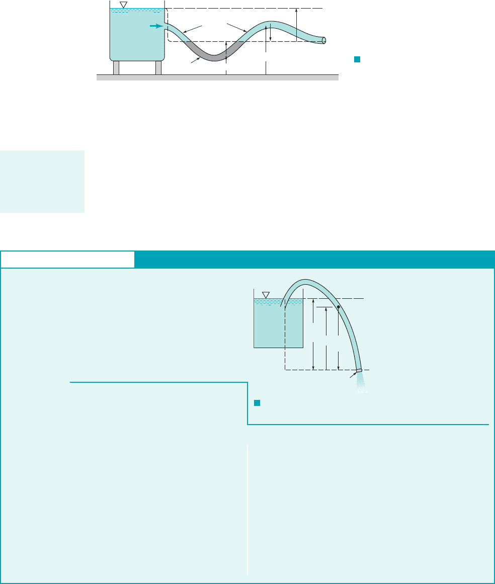
GIVEN A liquid can be siphoned from a container as shown in
Fig. E3.10a provided the end of the tube, point (3), is below the
free surface in the container, point (1), and the maximum elevation
of the tube, point (2), is “not too great.” Consider water at 60° F
being siphoned from a large tank through a constant diameter hose
Siphon and Cavitation
E
XAMPLE 3.10
as shown in Fig. E3.10b. The end of the siphon is 5 ft below the
bottom of the tank, and the atmospheric pressure is 14.7 psia.
FIND Determine the maximum height of the hill, H, over which
the water can be siphoned without cavitation occurring.
JWCL068_ch03_093-146.qxd 8/19/08 10:25 PM Page 117
118 Chapter 3 ■ Elementary Fluid Dynamics—The Bernoulli Equation
S
OLUTION
By using the fluid properties listed in Table 1.5 and repeating
the calculations for various fluids, the results shown in
Fig. E3.10c are obtained. The value of H is a function of both the
specific weight of the fluid, , and its vapor pressure, .p
v
g
If the flow is steady, inviscid, and incompressible we can apply
the Bernoulli equation along the streamline from 112to 122to 132as
follows:
(1)
With the tank bottom as the datum, we have
and Also, 1large tank2, 1open tank2,
1free jet2, and from the continuity equation or
because the hose is constant diameter, Thus, the speed of
the fluid in the hose is determined from Eq. 1 to be
Use of Eq. 1 between points 112and 122then gives the pressure
at the top of the hill as
(2)
From Table B.1, the vapor pressure of water at is
0.256 psia. Hence, for incipient cavitation the lowest pressure in
the system will be psia. Careful consideration of Eq. 2
and Fig. E3.10b will show that this lowest pressure will occur at
the top of the hill. Since we have used gage pressure at point 112
we must use gage pressure at point 122also. Thus,
psi and Eq. 2 gives
or
(Ans)
For larger values of H, vapor bubbles will form at point 122and the
siphon action may stop.
COMMENTS Note that we could have used absolute pres-
sure throughout 1 psia and psia2and ob-
tained the same result. The lower the elevation of point 132,the
larger the flowrate and, therefore, the smaller the value of H al-
lowed.
We could also have used the Bernoulli equation between 122
and 132, with to obtain the same value of H. In this case
it would not have been necessary to determine by use of the
Bernoulli equation between 112and 132.
The above results are independent of the diameter and length
of the hose 1provided viscous effects are not important2. Proper
design of the hose 1or pipe2is needed to ensure that it will not col-
lapse due to the large pressure difference 1vacuum2between the
inside and outside of the hose.
V
2
V
2
V
3
,
p
1
14.7p
2
0.256
H 28.2 ft
162.4 lb
ft
3
2115 H2ft
1
2
11.94 slugs
ft
3
2135.9 ft
s2
2
114.4 lb
in.
2
21144 in.
2
ft
2
2
p
2
0.256 14.7 14.4
1p
1
02,
p 0.256
60 °F
g1z
1
z
2
2
1
2
rV
2
2
p
2
p
1
1
2
rV
2
1
gz
1
1
2
rV
2
2
gz
2
p
2
35.9 ft
s V
2
V
3
22g1z
1
z
3
2 22132.2 ft
s
2
2315 1524 ft
V
2
V
3
.
A
2
V
2
A
3
V
3
,p
3
0
p
1
0V
1
0z
3
5 ft.
z
1
15 ft, z
2
H,
p
3
1
2
rV
2
3
gz
3
p
1
1
2
rV
2
1
gz
1
p
2
1
2
rV
2
2
gz
2
(2)
(3)
(1)
Water
(1)
(2)
(3)
5 ft
H
15 ft
F I G U R E E3.10
b
F I G U R E E3.10
c
F I G U R E E3.10
a
Fluid
40
35
30
25
20
15
10
5
0
H
, ft
Alcohol
Water
Gasoline
Carbon tet
3.6.3 Flowrate Measurement
Many types of devices using principles involved in the Bernoulli equation have been developed
to measure fluid velocities and flowrates. The Pitot-static tube discussed in Section 3.5 is an
example. Other examples discussed below include devices to measure flowrates in pipes and
JWCL068_ch03_093-146.qxd 8/19/08 10:25 PM Page 118
conduits and devices to measure flowrates in open channels. In this chapter we will consider
“ideal” flow meters—those devoid of viscous, compressibility, and other “real-world” effects.
Corrections for these effects are discussed in Chapters 8 and 10. Our goal here is to understand
the basic operating principles of these simple flow meters.
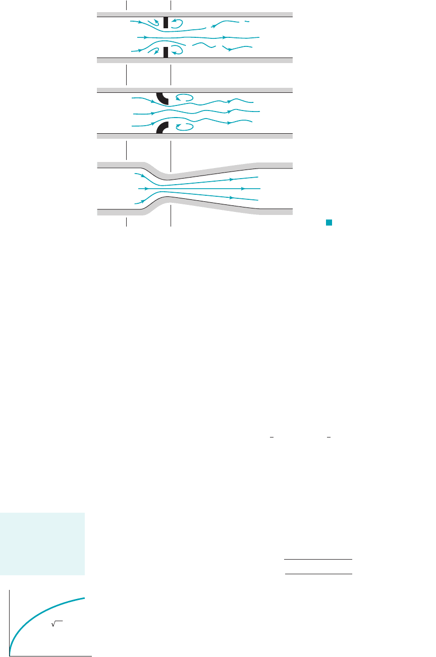
An effective way to measure the flowrate through a pipe is to place some type of restric-
tion within the pipe as shown in Fig. 3.18 and to measure the pressure difference between the
low-velocity, high-pressure upstream section 112, and the high-velocity, low-pressure downstream
section 122. Three commonly used types of flow meters are illustrated: the orifice meter, the noz-
zle meter, and the Venturi meter. The operation of each is based on the same physical principles—
an increase in velocity causes a decrease in pressure. The difference between them is a matter of
cost, accuracy, and how closely their actual operation obeys the idealized flow assumptions.
We assume the flow is horizontal steady, inviscid, and incompressible between
points 112and 122. The Bernoulli equation becomes
1The effect of nonhorizontal flow can be incorporated easily by including the change in elevation,
in the Bernoulli equation.2
If we assume the velocity profiles are uniform at sections 112and 122, the continuity equation
1Eq. 3.192can be written as
where is the small flow area at section 122. Combination of these two equations re-
sults in the following theoretical flowrate
(3.20)
Thus, as shown by the figure in the margin, for a given flow geometry and the flowrate
can be determined if the pressure difference, is measured. The actual measured flowrate,
will be smaller than this theoretical result because of various differences between the “real
world” and the assumptions used in the derivation of Eq. 3.20. These differences 1which are quite
consistent and may be as small as 1 to 2% or as large as 40%, depending on the geometry used2can
be accounted for by using an empirically obtained discharge coefficient as discussed in Section 8.6.1.
Q
actual
,
p
1
p
2
,
A
2
21A
1
Q A
2
B
21p
1
p
2
2
r31 1A
2
A
1
2
2
4
1A
2
6 A
1
2A
2
Q A
1
V
1
A
2
V
2
z
1
z
2
,
p
1
1
2
rV
2
1
p
2
1
2
rV
2
2
1z
1
z
2
2,
3.6 Examples of Use of the Bernoulli Equation 119
F I G U R E 3.18 Typical devices
for measuring flowrate in pipes.
(1) (2)
(1) (2)
Venturi
Nozzle
Orifice
The flowrate varies
as the square root
of the pressure dif-
ference across the
flow meter.
Q
Δp = p
1
– p
2
Q ~ Δp
JWCL068_ch03_093-146.qxd 8/19/08 10:25 PM Page 119
Other flow meters based on the Bernoulli equation are used to measure flowrates in open chan-
nels such as flumes and irrigation ditches. Two of these devices, the sluice gate and the sharp-crested
weir, are discussed below under the assumption of steady, inviscid, incompressible flow. These and
other open-channel flow devices are discussed in more detail in Chapter 10.
Sluice gates like those shown in Fig. 3.19a are often used to regulate and measure the flowrate
in open channels. As indicated in Fig. 3.19b, the flowrate, Q, is a function of the water depth up-
stream, the width of the gate, b, and the gate opening, a. Application of the Bernoulli equation
and continuity equation between points 112and 122can provide a good approximation to the actual
flowrate obtained. We assume the velocity profiles are uniform sufficiently far upstream and down-
stream of the gate.
z
1
,
120 Chapter 3 ■ Elementary Fluid Dynamics—The Bernoulli Equation
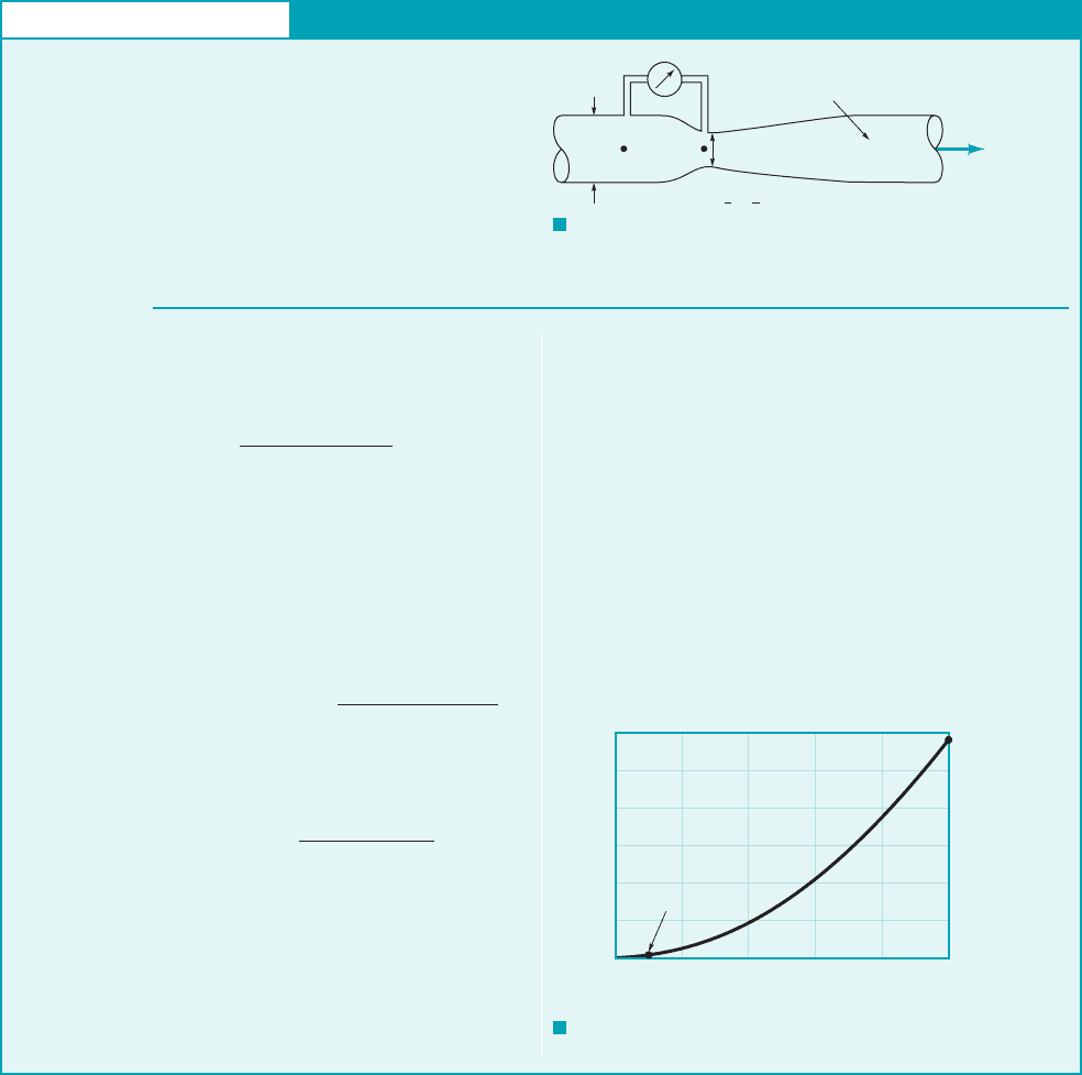
GIVEN Kerosene flows through the Venturi
meter shown in Fig. E3.11a with flowrates between 0.005 and
FIND Determine the range in pressure difference,
needed to measure these flowrates.
p
1
p
2
,
0.050 m
3
s.
1SG 0.852
Venturi Meter
E
XAMPLE 3.11
D
1
= 0.1 m
(1)
(2)
0.005 m
3
/s
<
Q
<
0.050 m
3
/s
D
2
= 0.06 m
Kerosene,
SG = 0.85
Q
F I G U R E E3.11
a
F I G U R E E3.11
b
S
OLUTION
results presented here are independent of the particular flow
meter geometry—an orifice, nozzle, or Venturi meter 1see
Fig. 3.182.
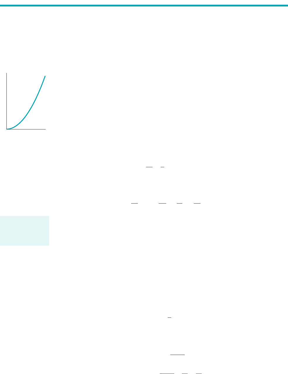
It is seen from Eq. 3.20 that the flowrate varies as the
square root of the pressure difference. Hence, as indicated by
the numerical results and shown in Fig. E3.11b, a 10-fold in-
crease in flowrate requires a 100-fold increase in pressure dif-
ference. This nonlinear relationship can cause difficulties when
measuring flowrates over a wide range of values. Such mea-
surements would require pressure transducers with a wide
range of operation. An alternative is to use two flow meters in
parallel—one for the larger and one for the smaller flowrate
ranges.
If the flow is assumed to be steady, inviscid, and incompressible,
the relationship between flowrate and pressure is given by Eq.
3.20. This can be rearranged to give
With the density of the flowing fluid
and the area ratio
the pressure difference for the smallest flowrate is
Likewise, the pressure difference for the largest flowrate is
Thus,
(Ans)
COMMENTS These values represent the pressure differ-
ences for inviscid, steady, incompressible conditions. The ideal
1.16 kPa p
1
p
2
116 kPa
1.16 10
5
N
m
2
116 kPa
p
1
p
2
10.052
2
18502
11 0.36
2
2
231p
4210.062
2
4
2
1160 N
m
2
1.16 kPa
p
1
p
2
10.005 m
3
s2
2
1850 kg
m
3
2
11 0.36
2
2
2 31p
4210.06 m2
2
4
2
0.36A
2
A
1
1D
2
D
1
2
2
10.06 m
0.10 m2
2
r SG r
H
2
O
0.8511000 kg
m
3
2 850 kg
m
3
p
1
p
2
Q
2
r31 1A
2
A
1
2
2
4
2 A
2
2
p
1
–
p
2
, kPa
(0.005 m
3
/s, 1.16 kPa)
(0.05 m
3
/s, 116 kPa)
0
0
20
40
60
80
100
120
0.01 0.02 0.03 0.04 0.05
Q
, m
3
/s
JWCL068_ch03_093-146.qxd 8/19/08 10:26 PM Page 120
Thus, we apply the Bernoulli equation between points on the free surfaces at 112and 122to
give
Also, if the gate is the same width as the channel so that A
1
bz
1
and A
2
bz
2
, the continuity
equation gives
With the fact that these equations can be combined and rearranged to give the flowrate
as
(3.21)
In the limit of this result simply becomes
This limiting result represents the fact that if the depth ratio, is large, the kinetic energy of
the fluid upstream of the gate is negligible and the fluid velocity after it has fallen a distance
is approximately
The results of Eq. 3.21 could also be obtained by using the Bernoulli equation between points
132and 142and the fact that and since the streamlines at these sections are straight.
In this formulation, rather than the potential energies at 112and 122, we have the pressure contri-
butions at 132and 142.
The downstream depth, not the gate opening, a, was used to obtain the result of Eq. 3.21.
As was discussed relative to flow from an orifice 1Fig. 3.142, the fluid cannot turn a sharp cor-
ner. A vena contracta results with a contraction coefficient, less than 1. Typically is
approximately 0.61 over the depth ratio range of For larger values of the
value of increases rapidly.C
c
a
z
1
0 6 a
z
1
6 0.2.
C
c
C
c
z
2
a,
90°
z
2
,
p
4
gz
2
p
3
gz
1
V
2
12gz
1
.1z
1
z
2
2 z
1
z
1
z
2
,
Q z
2
b12gz
1
z
1
z
2
Q z
2
b
B
2g1z
1
z
2
2
1 1z
2
z
1
2
2
p
1
p
2
0,
Q A
1
V
1
bV
1
z
1
A
2
V
2
bV
2
z
2
p
1
1
2
rV
2
1
gz
1
p
2
1
2
rV
2
2
gz
2
3.6 Examples of Use of the Bernoulli Equation 121
Sluice gate
width =
b
(1)
(2)
(4)(3)
V
1
z
1
a
V
2
z
2
(b)(a)
Sluice gates
b
a
Q
F I G U R E 3.19 Sluice gate geometry. (Photograph courtesy of Plasti-Fab, Inc.)
The flowrate under
a sluice gate de-
pends on the water
depths on either
side of the gate.
GIVEN Water flows under the sluice gate shown in Fig. E3.12a.
FIND Determine the approximate flowrate per unit width of
the channel.
Sluice Gate
E
XAMPLE 3.12
JWCL068_ch03_093-146.qxd 8/19/08 10:26 PM Page 121
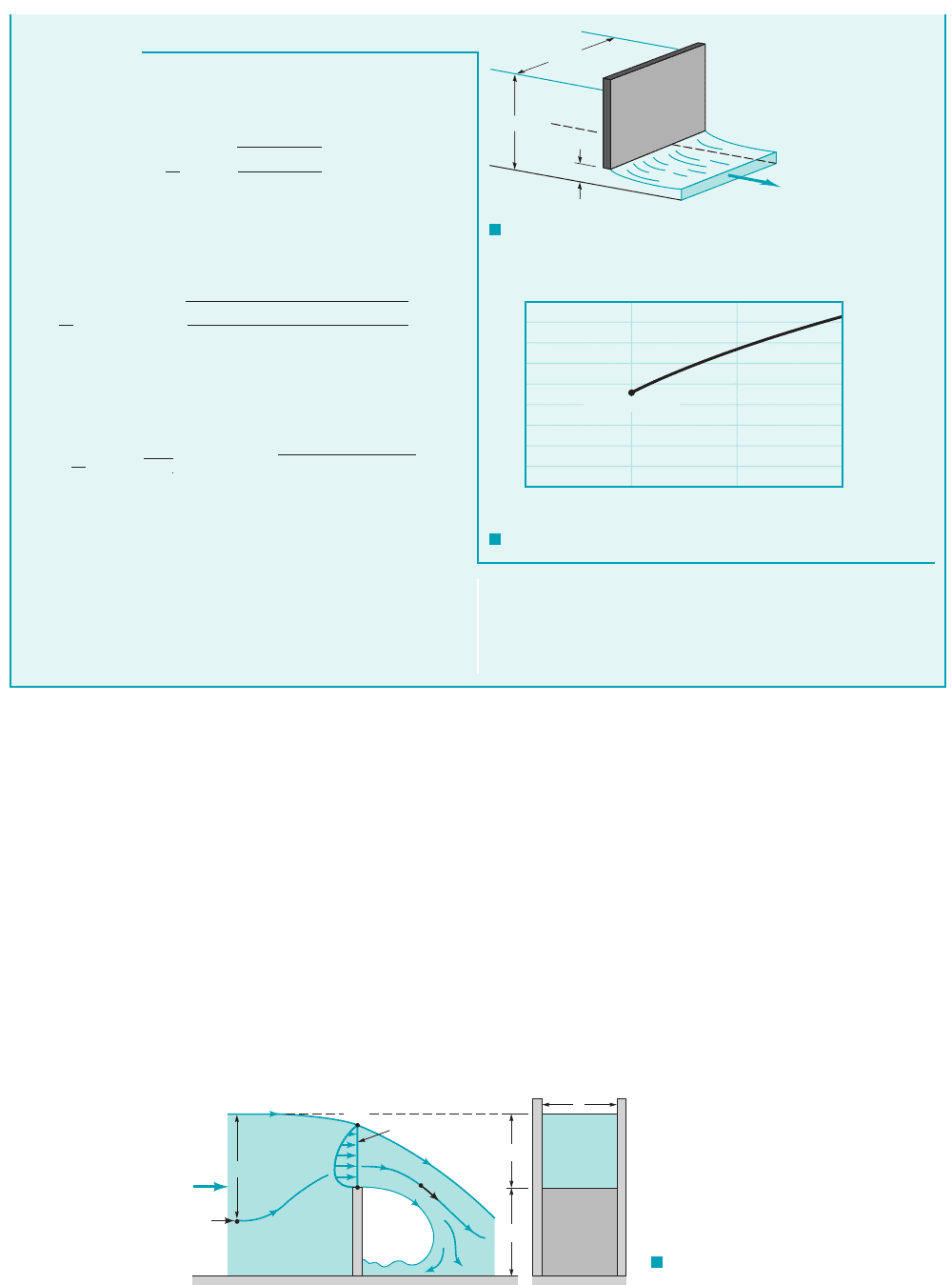
Another device used to measure flow in an open channel is a weir. A typical rectangular,
sharp-crested weir is shown in Fig. 3.20. For such devices the flowrate of liquid over the top of
the weir plate is dependent on the weir height, the width of the channel, b, and the head, H,
of the water above the top of the weir. Application of the Bernoulli equation can provide a sim-
ple approximation of the flowrate expected for these situations, even though the actual flow is
quite complex.
Between points 112and 122the pressure and gravitational fields cause the fluid to accelerate
from velocity to velocity At 112the pressure is while at 122the pressure is essen-
tially atmospheric, Across the curved streamlines directly above the top of the weir plate
1section a–a2, the pressure changes from atmospheric on the top surface to some maximum value
within the fluid stream and then to atmospheric again at the bottom surface. This distribution is
indicated in Fig. 3.20. Such a pressure distribution, combined with the streamline curvature and
gravity, produces a rather nonuniform velocity profile across this section. This velocity distribu-
tion can be obtained from experiments or a more advanced theory.
p
2
0.
p
1
gh,V
2
.V
1
P
w
,
122 Chapter 3 ■ Elementary Fluid Dynamics—The Bernoulli Equation
S
OLUTION
flowrate is not directly proportional to the flow depth. Thus,
for example, if during flood conditions the upstream depth dou-
bled from , the flowrate per unit width of
the channel would not double, but would increase only from
.4.61 m
2
s to 6.67 m
2
s
z
1
5 m to z
1
10 m
Under the assumptions of steady, inviscid, incompressible flow,
we can apply Eq. 3.21 to obtain the flowrate per unit width,
as
In this instance m and so the ratio
and we can assume that the contraction co-
efficient is approximately Thus,
and we obtain the flowrate
(Ans)
COMMENT
If we consider and neglect the kinetic
energy of the upstream fluid, we would have
In this case the difference in Q with or without including is not
too significant because the depth ratio is fairly large
Thus, it is often reasonable to
neglect the kinetic energy upstream from the gate compared to
that downstream of it.
By repeating the calculations for various flow depths, , the
results shown in Fig. E3.12b are obtained. Note that the
z
1
1z
1
z
2
5.0
0.488 10.22.
V
1
4.83 m
2
s
Q
b
z
2
12gz
1
0.488 m 2219.81 m
s
2
215.0 m2
z
1
z
2
4.61 m
2
s
Q
b
10.488 m2
B
219.81 m
s
2
215.0 m 0.488 m2
1 10.488 m
5.0 m2
2
10.80 m2 0.488 m
z
2
C
c
a 0.61C
c
0.61.
a
z
1
0.16 6 0.20,
a 0.80 mz
1
5.0
Q
b
z
2
B
2g1z
1
z
2
2
1 1z
2
z
1
2
2
Q
b,
Q
5.0 m
6.0 m
0.8 m
F I G U R E E3.12
a
F I G U R E E3.12
b
9
8
7
6
5
4
3
2
1
0
05
z
1
, m
Q/b, m
2
/s
10 15
(5m, 4.61 m
2
/s)
F I G U R E 3.20
Rectangular, sharp-crested weir geometry.
Q
Pressure distribution
Width =
b
H
a
a
Weir
plate
(1)
V
1
(2)
V
2
P
w
h
b
JWCL068_ch03_093-146.qxd 8/19/08 10:26 PM Page 122
For now, we will take a very simple approach and assume that the weir flow is similar in
many respects to an orifice-type flow with a free streamline. In this instance we would expect the
average velocity across the top of the weir to be proportional to and the flow area for this
rectangular weir to be proportional to Hb. Hence, it follows that
where is a constant to be determined.
Simple use of the Bernoulli equation has provided a method to analyze the relatively com-
plex flow over a weir. The correct functional dependence of Q on H has been obtained
as indicated by the figure in the margin), but the value of the coefficient is unknown. Even a
more advanced analysis cannot predict its value accurately. As is discussed in Chapter 10, exper-
iments are used to determine the value of C
1
.
C
1
1Q ⬃ H
3
2
,
C
1
Q C
1
Hb 12gH C
1
b 12g H
3
2
12gH
3.7 The Energy Line and the Hydraulic Grade Line 123
GIVEN Water flows over a triangular weir, as is shown in Fig.
E3.13.
FIND Based on a simple analysis using the Bernoulli equation,
determine the dependence of the flowrate on the depth H. If the
flowrate is when estimate the flowrate when the
depth is increased to H 3H
0
.
H H
0
,Q
0
Weir
E
XAMPLE 3.13
S
OLUTION
(Ans)
COMMENT
Note that for a triangular weir the flowrate is
proportional to whereas for the rectangular weir discussed
above, it is proportional to The triangular weir can be accu-
rately used over a wide range of flowrates.
H
3
2
.
H
5
2
,
15.6
Q
3H
0
Q
H
0
C
2
tan1u
22 12g 13H
0
2
5
2
C
2
tan1u
22 12g 1H
0
2
5
2
With the assumption that the flow is steady, inviscid, and incom-
pressible, it is reasonable to assume from Eq. 3.18 that the aver-
age speed of the fluid over the triangular notch in the weir plate is
proportional to Also, the flow area for a depth of H is
H The combination of these two ideas gives
(Ans)
where is an unknown constant to be determined experimentally.
Thus, an increase in the depth by a factor of three 1from to
2results in an increase of the flowrate by a factor of3H
0
H
0
C
2
Q AV H
2
tan
u
2
1C
2
12gH2 C
2
tan
u
2
12g H
5
2
3H tan 1u
224.
12gH
.
Q ~ H
3/2
Q
H
HH
H
tan
_
2
θ
θ
F I G U R E E3.13
The hydraulic
grade line and en-
ergy line are graph-
ical forms of the
Bernoulli equation.
As was discussed in Section 3.4, the Bernoulli equation is actually an energy equation repre-
senting the partitioning of energy for an inviscid, incompressible, steady flow. The sum of the
various energies of the fluid remains constant as the fluid flows from one section to another. A
useful interpretation of the Bernoulli equation can be obtained through the use of the concepts
of the hydraulic grade line 1HGL2and the energy line 1EL2. These ideas represent a geometri-
cal interpretation of a flow and can often be effectively used to better grasp the fundamental
processes involved.
For steady, inviscid, incompressible flow the total energy remains constant along a stream-
line. The concept of “head” was introduced by dividing each term in Eq. 3.7 by the specific weight,
to give the Bernoulli equation in the following form
(3.22)
p
g
V
2
2g
z constant on a streamline H
g rg,
3.7 The Energy Line and the Hydraulic Grade Line
JWCL068_ch03_093-146.qxd 9/23/08 9:11 AM Page 123
Each of the terms in this equation has the units of length 1feet or meters2and represents a certain
type of head. The Bernoulli equation states that the sum of the pressure head, the velocity head,
and the elevation head is constant along a streamline. This constant is called the total head, H.
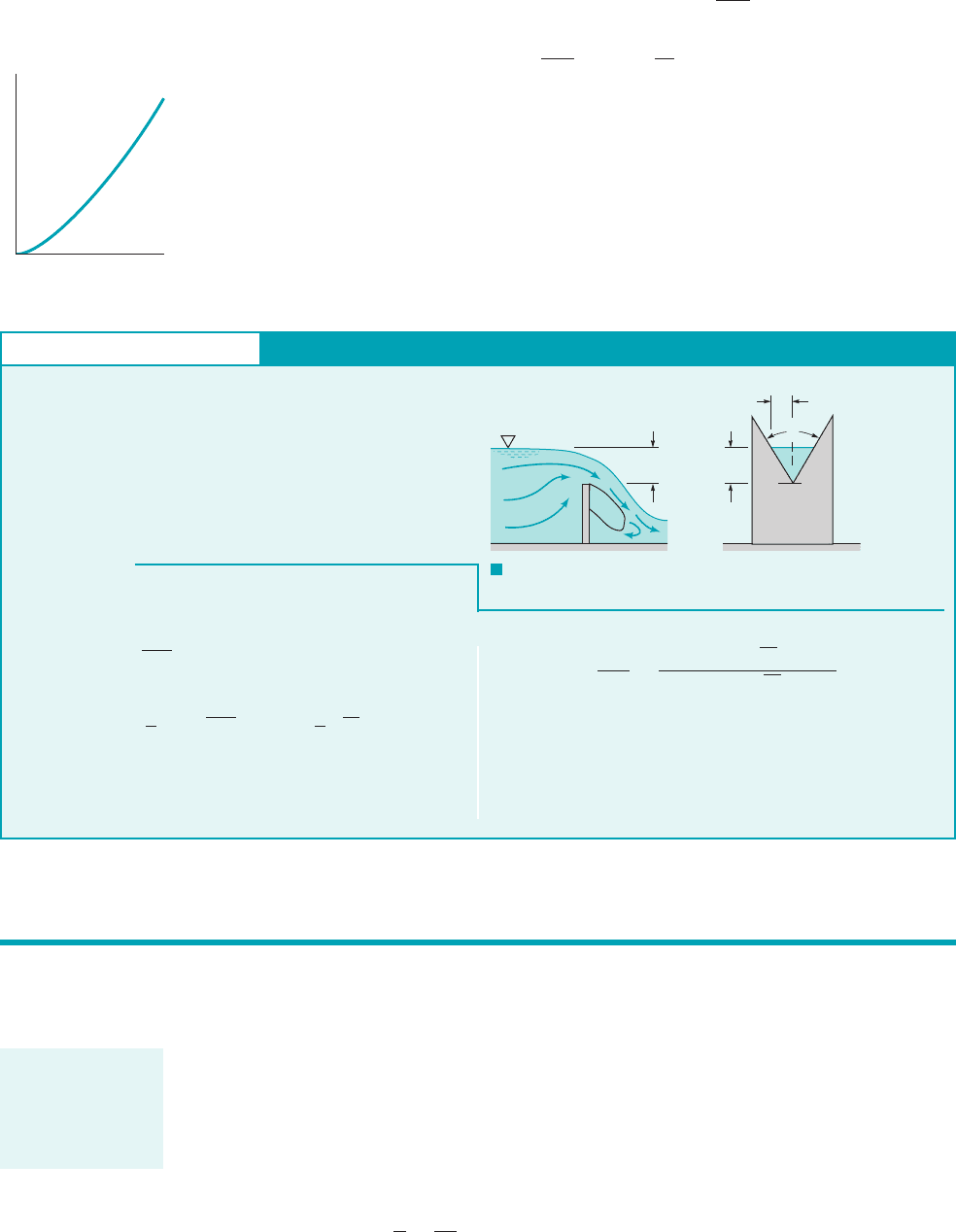
The energy line is a line that represents the total head available to the fluid. As shown in
Fig. 3.21, the elevation of the energy line can be obtained by measuring the stagnation pressure
with a Pitot tube. 1A Pitot tube is the portion of a Pitot-static tube that measures the stagnation
pressure. See Section 3.5.2The stagnation point at the end of the Pitot tube provides a measure-
ment of the total head 1or energy2of the flow. The static pressure tap connected to the piezometer
tube shown, on the other hand, measures the sum of the pressure head and the elevation head,
This sum is often called the piezometric head. The static pressure tap does not measure
the velocity head.
According to Eq. 3.22, the total head remains constant along the streamline 1provided the as-
sumptions of the Bernoulli equation are valid2. Thus, a Pitot tube at any other location in the flow
will measure the same total head, as is shown in the figure. The elevation head, velocity head, and
pressure head may vary along the streamline, however.
The locus of elevations provided by a series of Pitot tubes is termed the energy line, EL.
The locus provided by a series of piezometer taps is termed the hydraulic grade line, HGL. Un-
der the assumptions of the Bernoulli equation, the energy line is horizontal. If the fluid veloc-
ity changes along the streamline, the hydraulic grade line will not be horizontal. If viscous effects
are important 1as they often are in pipe flows2, the total head does not remain constant due to a
loss in energy as the fluid flows along its streamline. This means that the energy line is no longer
horizontal. Such viscous effects are discussed in Chapters 5 and 8.
The energy line and hydraulic grade line for flow from a large tank are shown in Fig. 3.22.
If the flow is steady, incompressible, and inviscid, the energy line is horizontal and at the eleva-
tion of the liquid in the tank 1since the fluid velocity in the tank and the pressure on the surface
p
g z.
124 Chapter 3 ■ Elementary Fluid Dynamics—The Bernoulli Equation
H
V
2
/2g
p/␥
z
F I G U R E 3.21 Representation of the energy line and the
hydraulic grade line.
Q
H
Static
Stagnation
z
1
p
1
/
V
1
2
/2g
V
2
/2g
z
z
2
p
2
/
V
2
2
___
2g
Hydraulic
grade line (HGL)
Energy line (EL)
Datum
p/
γ
γ
γ
F I G U R E 3.22 The energy line
and hydraulic grade line for flow from a tank.
HGL
EL
(3)
(2)
(1)
V
1
= p
1
= 0
H = z
1
p
2__
V
2
2
___
2
g
z
2
z
3
V
3
2
___
2
g
p
3
= 0
γ
Under the assump-
tions of the Bernoulli
equation, the energy
line is horizontal.
JWCL068_ch03_093-146.qxd 8/19/08 10:27 PM Page 124
are zero2. The hydraulic grade line lies a distance of one velocity head, below the energy
line. Thus, a change in fluid velocity due to a change in the pipe diameter results in a change in
the elevation of the hydraulic grade line. At the pipe outlet the pressure head is zero 1gage2so the
pipe elevation and the hydraulic grade line coincide.
The distance from the pipe to the hydraulic grade line indicates the pressure within the pipe,
as is shown in Fig. 3.23. If the pipe lies below the hydraulic grade line, the pressure within the
pipe is positive 1above atmospheric2. If the pipe lies above the hydraulic grade line, the pressure is
negative 1below atmospheric2. Thus, a scale drawing of a pipeline and the hydraulic grade line can
be used to readily indicate regions of positive or negative pressure within a pipe.
V
2
2g,
3.7 The Energy Line and the Hydraulic Grade Line 125
For flow below
(above) the hy-
draulic grade line,
the pressure is
positive (negative).
F I G U R E 3.23
Use of the energy line and the
hydraulic grade line.
Q
p > 0
p < 0
p/
z
z
V
2
__
2g
EL
HGL
γ
p/
γ
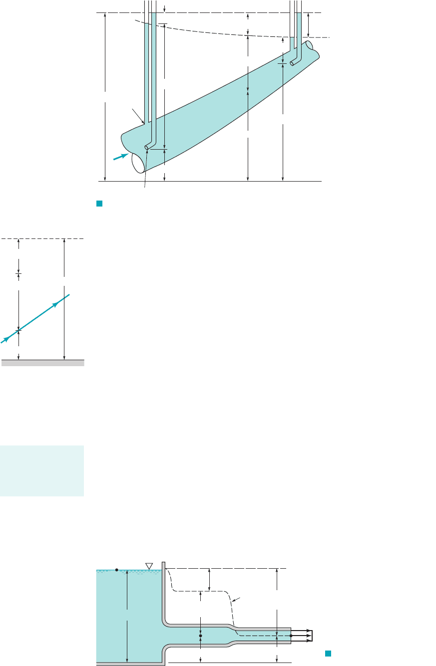
GIVEN Water is siphoned from the tank shown in Fig. E3.14
through a hose of constant diameter. A small hole is found in the
hose at location 112as indicated.
FIND When the siphon is used, will water leak out of the hose,
or will air leak into the hose, thereby possibly causing the siphon
to malfunction?
Energy Line and Hydraulic Grade Line
E
XAMPLE 3.14
S
OLUTION
COMMENT
In practice, viscous effects may be quite impor-
tant, making this simple analysis 1horizontal energy line2incor-
rect. However, if the hose is “not too small diameter,” “not too
long,” the fluid “not too viscous,” and the flowrate “not too large,”
the above result may be very accurate. If any of these assumptions
are relaxed, a more detailed analysis is required 1see Chapter 82.If
the end of the hose were closed so that the flowrate were zero, the
hydraulic grade line would coincide with the energy line
1 throughout2, the pressure at 112would be greater than
atmospheric, and water would leak through the hole at 112.
V
2
2g 0
Whether air will leak into or water will leak out of the hose de-
pends on whether the pressure within the hose at 112is less than or
greater than atmospheric. Which happens can be easily determined
by using the energy line and hydraulic grade line concepts. With
the assumption of steady, incompressible, inviscid flow it follows
that the total head is constant—thus, the energy line is horizontal.
Since the hose diameter is constant, it follows from the continuity
equation that the water velocity in the hose is con-
stant throughout. Thus, the hydraulic grade line is a constant dis-
tance, below the energy line as shown in Fig. E3.14. Since the
pressure at the end of the hose is atmospheric, it follows that the hy-
draulic grade line is at the same elevation as the end of the hose out-
let. The fluid within the hose at any point above the hydraulic grade
line will be at less than atmospheric pressure.
(Ans)
Thus, air will leak into the hose through
the hole at point 112.
V
2
2g,
1AV constant2
F I G U R E E3.14
Valve
HGL with valve open
HGL with valve closed and
EL with valve open or closed
(1)
V
2
__
2
g
p
_
γ
z
The above discussion of the hydraulic grade line and the energy line is restricted to ideal sit-
uations involving inviscid, incompressible flows. Another restriction is that there are no “sources”
or “sinks” of energy within the flow field. That is, there are no pumps or turbines involved. Al-
terations in the energy line and hydraulic grade line concepts due to these devices are discussed in
Chapters 5 and 8.
JWCL068_ch03_093-146.qxd 8/19/08 10:27 PM Page 125
126 Chapter 3 ■ Elementary Fluid Dynamics—The Bernoulli Equation
The Bernoulli
equation can be
modified for com-
pressible flows.
Δp ~ V
2
V
Δp
Proper use of the Bernoulli equation requires close attention to the assumptions used in its de-
rivation. In this section we review some of these assumptions and consider the consequences of
incorrect use of the equation.
3.8.1 Compressibility Effects
One of the main assumptions is that the fluid is incompressible. Although this is reasonable for
most liquid flows, it can, in certain instances, introduce considerable errors for gases.
In the previous section, we saw that the stagnation pressure, , is greater than the static
pressure, , by an amount provided that the density remains con-
stant. If this dynamic pressure is not too large compared with the static pressure, the density change
between two points is not very large and the flow can be considered incompressible. However, since
the dynamic pressure varies as the error associated with the assumption that a fluid is incom-
pressible increases with the square of the velocity of the fluid, as indicated by the figure in the mar-
gin. To account for compressibility effects we must return to Eq. 3.6 and properly integrate the term
when is not constant.
A simple, although specialized, case of compressible flow occurs when the temperature of a
perfect gas remains constant along the streamline—isothermal flow. Thus, we consider
where T is constant. 1In general, p, and T will vary.2For steady, inviscid, isothermal flow, Eq.
3.6 becomes
where we have used The pressure term is easily integrated and the constant of integration
evaluated if and are known at some location on the streamline. The result is
(3.23)
Equation 3.23 is the inviscid, isothermal analog of the incompressible Bernoulli equation. In the
limit of small pressure difference, with and Eq. 3.23
reduces to the standard incompressible Bernoulli equation. This can be shown by use of the ap-
proximation for small The use of Eq. 3.23 in practical applications is restricted by
the inviscid flow assumption, since 1as is discussed in Section 11.52most isothermal flows are ac-
companied by viscous effects.
A much more common compressible flow condition is that of isentropic 1constant entropy2
flow of a perfect gas. Such flows are reversible adiabatic processes—“no friction or heat transfer”—
and are closely approximated in many physical situations. As discussed fully in Chapter 11, for
isentropic flow of a perfect gas the density and pressure are related by where k is the
specific heat ratio and C is a constant. Hence, the integral of Eq. 3.6 can be evaluated
as follows. The density can be written in terms of the pressure as so that Eq. 3.6
becomes
The pressure term can be integrated between points 112and 122on the streamline and the constant
C evaluated at either point or to give the following:
a
k
k 1
b a
p
2
r
2
p
1
r
1
b
C
1
k
p2
p1
p
1
k
dp C
1
k
a
k
k 1
b 3p
1k12
k
2
p
1k12
k
1
4
C
1
k
p
2
1
k
r
2
21C
1
k
p
1
1
k
r
1
C
1
k
p
1
k
dp
1
2
V
2
gz constant
r p
1
k
C
1
k
dp
r
p
r
k
C,
e.ln11 e2 e
e 1p
1
p
2
1 1p
1
p
2
2
p
2
1 e,
V
2
1
2g
z
1
RT
g
ln a
p
1
p
2
b
V
2
2
2g
z
2
V
1
z
1
, p
1
,
r p
RT.
RT
dp
p
1
2
V
2
gz constant
r,
p rRT,
r
dp
r
V
2
,
¢p p
stag
p
static
rV
2
2,p
static
p
stag
3.8 Restrictions on Use of the Bernoulli Equation
JWCL068_ch03_093-146.qxd 8/19/08 10:27 PM Page 126