Munson B.R. Fundamentals of Fluid Mechanics
Подождите немного. Документ загружается.

where p and V are the pressure and velocity of the fluid upstream of point 122. The outer tube is
made with several small holes at an appropriate distance from the tip so that they measure the sta-
tic pressure. If the effect of the elevation difference between 112and 142is negligible, then
By combining these two equations we see that
which can be rearranged to give
(3.16)
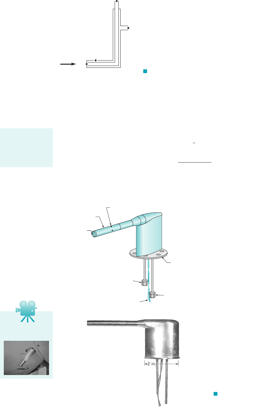
The actual shape and size of Pitot-static tubes vary considerably. A typical Pitot-static probe used
to determine aircraft airspeed is shown in Fig. 3.7. (See Fig. E3.6a also.)
V 221p
3
p
4
2
r
p
3
p
4
1
2
rV
2
p
4
p
1
p
3.5 Static, Stagnation, Dynamic, and Total Pressure 107
V
p
(1)
(2)
(4)
(3)
F I G U R E 3.6 The Pitot-static tube.
Pitot-static tubes
measure fluid ve-
locity by converting
velocity into pres-
sure.
(
b
)
Four static pressure ports
Heated outer case
Stagnation
pressure port
Stagnation pressure fitting
Heater leads
Mounting flange
Static pressure fitting
(a)
F I G U R E 3.7 Airplane
Pitot-static probe. (a) Schematic, (b) Photo-
graph, (Photograph courtesy of SpaceAge
Control, Inc.)
V3.8 Airspeed
indicator
JWCL068_ch03_093-146.qxd 8/19/08 10:23 PM Page 107
108 Chapter 3 ■ Elementary Fluid Dynamics—The Bernoulli Equation
Fluids in the News
Bugged and plugged Pitot tubes Although a Pitot tube is a sim-
ple device for measuring aircraft airspeed, many airplane acci-
dents have been caused by inaccurate Pitot tube readings. Most of
these accidents are the result of having one or more of the holes
blocked and, therefore, not indicating the correct pressure
(speed). Usually this is discovered during takeoff when time to re-
solve the issue is short. The two most common causes for such a
blockage are either that the pilot (or ground crew) has forgotten to
remove the protective Pitot tube cover, or that insects have built
their nest within the tube where the standard visual check cannot
detect it. The most serious accident (in terms of number of fatali-
ties) caused by a blocked Pitot tube involved a Boeing 757 and
occurred shortly after takeoff from Puerto Plata in the Dominican
Republic. The incorrect airspeed data was automatically fed to
the computer, causing the autopilot to change the angle of attack
and the engine power. The flight crew became confused by the
false indications, the aircraft stalled, and then plunged into the
Caribbean Sea killing all aboard. (See Problem 3.30.)
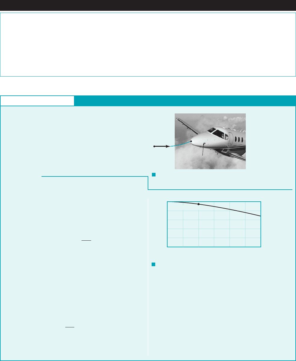
GIVEN An airplane flies 200 mihr at an elevation of 10,000 ft
in a standard atmosphere as shown in Fig. E3.6a.
FIND Determine the pressure at point 112far ahead of the air-
plane, the pressure at the stagnation point on the nose of the
airplane, point 122, and the pressure difference indicated by a Pitot-
static probe attached to the fuselage.
S
OLUTION
F I G U R E E3.6
a
(Photo
courtesy of Hawker Beechcraft.)
F I G U R E E3.6
b
Pitot-Static Tube
It was assumed that the flow is incompressible—the density re-
mains constant from 112to 122. However, since a change in
pressure 1or temperature2will cause a change in density. For this rel-
atively low speed, the ratio of the absolute pressures is nearly unity
so that
the density change is negligible. However, by repeating the calcula-
tions for various values of the speed, , the results shown in Fig.
E3.6b are obtained. Clearly at the 500 to 600 mph speeds nor-
mally flown by commercial airliners, the pressure ratio is such
that density changes are important. In such situations it is neces-
sary to use compressible flow concepts to obtain accurate results.
1See Section 3.8.1 and Chapter 11.2
V
1
3i.e., p
1
p
2
110.11 psia2
110.11 0.524 psia2 0.9514,
r p
RT,
(2)
(1)
Pitot-static tube
V
1
= 200 mph
E
XAMPLE 3.6
From Table C.1 we find that the static pressure at the altitude
given is
(Ans)
Also, the density is
If the flow is steady, inviscid, and incompressible and eleva-
tion changes are neglected, Eq. 3.13 becomes
With and 1since the co-
ordinate system is fixed to the airplane2we obtain
Hence, in terms of gage pressure
(Ans)
Thus, the pressure difference indicated by the Pitot-static tube is
(Ans)
COMMENTS
Note that it is very easy to obtain incorrect re-
sults by using improper units. Do not add and Recall
that 1slug
ft
3
21ft
2
s
2
2 1slug
#
ft
s
2
2
1ft
2
2 lb
ft
2
.
lb
ft
2
.lb
in.
2
p
2
p
1
rV
2
1
2
0.524 psi
p
2
75.4 lb
ft
2
0.524 psi
11456 75.42 lb
ft
2
1abs2
p
2
1456 lb
ft
2
10.001756 slugs
ft
3
21293
2
ft
2
s
2
2
2
V
2
0V
1
200 mi
hr 293 ft
s
p
2
p
1
rV
2
1
2
r 0.001756 slug
ft
3
.
p
1
1456 lb
ft
2
1abs2 10.11 psia
(200 mph, 0.951)
1
0.8
0.6
0.4
0.2
0
0 100 200 300
V
1
, mph
p
1
/
p
2
400 500 600
The Pitot-static tube provides a simple, relatively inexpensive way to measure fluid speed.
Its use depends on the ability to measure the static and stagnation pressures. Care is needed to
obtain these values accurately. For example, an accurate measurement of static pressure requires
that none of the fluid’s kinetic energy be converted into a pressure rise at the point of
JWCL068_ch03_093-146.qxd 8/19/08 10:23 PM Page 108
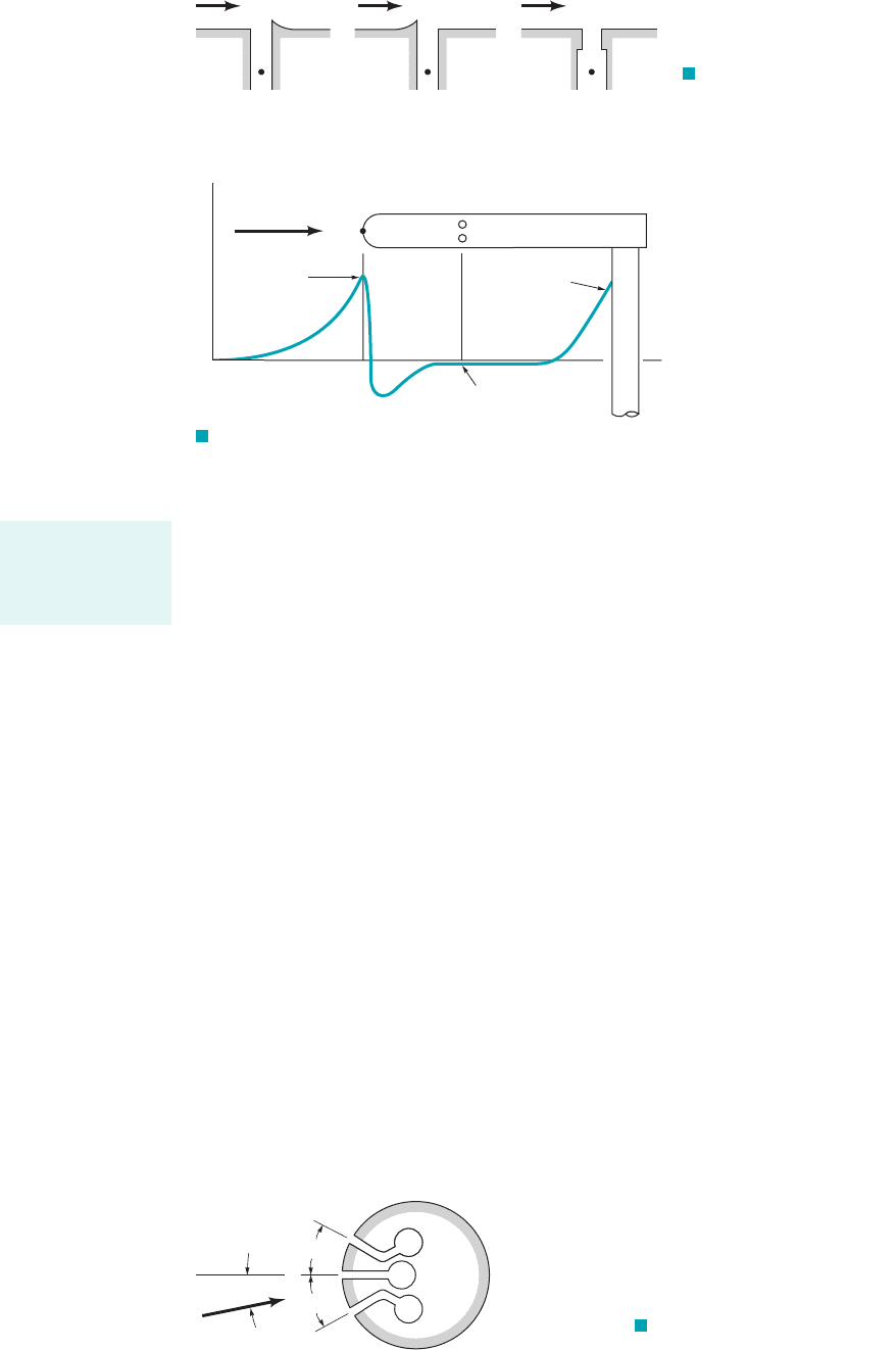
measurement. This requires a smooth hole with no burrs or imperfections. As indicated in
Fig. 3.8, such imperfections can cause the measured pressure to be greater or less than the ac-
tual static pressure.
Also, the pressure along the surface of an object varies from the stagnation pressure at
its stagnation point to values that may be less than the free stream static pressure. A typical
pressure variation for a Pitot-static tube is indicated in Fig. 3.9. Clearly it is important that
the pressure taps be properly located to ensure that the pressure measured is actually the static
pressure.
In practice it is often difficult to align the Pitot-static tube directly into the flow direction. Any
misalignment will produce a nonsymmetrical flow field that may introduce errors. Typically, yaw
angles up to 12 to 1depending on the particular probe design2give results that are less than 1%
in error from the perfectly aligned results. Generally it is more difficult to measure static pressure
than stagnation pressure.
One method of determining the flow direction and its speed 1thus the velocity2is to use a di-
rectional-finding Pitot tube as is illustrated in Fig. 3.10. Three pressure taps are drilled into a small
circular cylinder, fitted with small tubes, and connected to three pressure transducers. The cylinder
is rotated until the pressures in the two side holes are equal, thus indicating that the center hole
points directly upstream. The center tap then measures the stagnation pressure. The two side holes
are located at a specific angle so that they measure the static pressure. The speed is
then obtained from
The above discussion is valid for incompressible flows. At high speeds, compressibility be-
comes important 1the density is not constant2and other phenomena occur. Some of these ideas are
discussed in Section 3.8, while others 1such as shockwaves for supersonic Pitot-tube applications2
are discussed in Chapter 11.
The concepts of static, dynamic, stagnation, and total pressure are useful in a variety of flow
problems. These ideas are used more fully in the remainder of the book.
V 321p
2
p
1
2
r4
1
2
.
1b 29.5°2
20°
3.5 Static, Stagnation, Dynamic, and Total Pressure 109
F I G U R E 3.8 Incor-
rect and correct design of static
pressure taps.
V
p
V
p
V
p
(1)
p
1
= p
(1)
p
1
< p
(1)
p
1
> p
Accurate measure-
ment of static pres-
sure requires great
care.
F I G U R E 3.9 Typical pressure distribution along
a Pitot-static tube.
V
Stagnation
pressure on
stem
Static
pressure
Stem
Tube
(1)
(1)
(2)
(2)
Stagnation
pressure at
tip
0
p
F I G U R E 3.10 Cross section
of a directional-finding Pitot-static tube.
β
β
θ
V
p
(1)
(2)
(3)
If = 0
θ
ρ
p
1
=
p
3
=
p
p
2
=
p
+
V
2
1_
2
JWCL068_ch03_093-146.qxd 8/19/08 10:23 PM Page 109
110 Chapter 3 ■ Elementary Fluid Dynamics—The Bernoulli Equation
In this section we illustrate various additional applications of the Bernoulli equation. Between any
two points, 112and 122, on a streamline in steady, inviscid, incompressible flow the Bernoulli equa-
tion can be applied in the form
(3.17)
Obviously if five of the six variables are known, the remaining one can be determined. In many in-
stances it is necessary to introduce other equations, such as the conservation of mass. Such consid-
erations will be discussed briefly in this section and in more detail in Chapter 5.
3.6.1 Free Jets
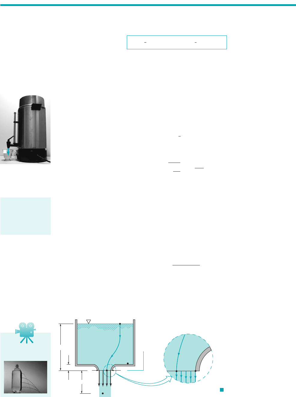
One of the oldest equations in fluid mechanics deals with the flow of a liquid from a large reservoir.
A modern version of this type of flow involves the flow of coffee from a coffee urn as indicated by
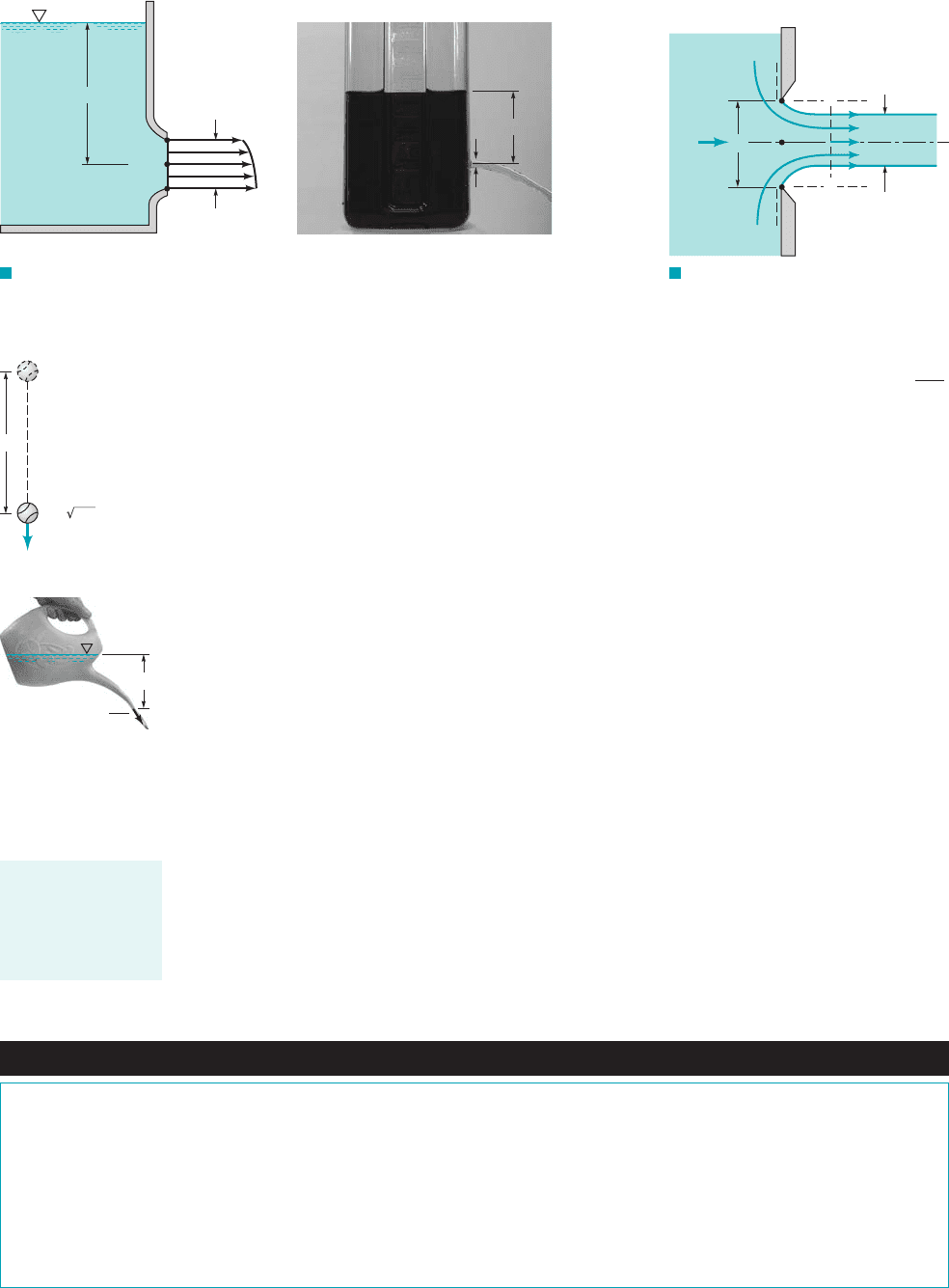
the figure in the margin. The basic principles of this type of flow are shown in Fig. 3.11 where a jet
of liquid of diameter d flows from the nozzle with velocity V. 1A nozzle is a device shaped to ac-
celerate a fluid.2Application of Eq. 3.17 between points 112and 122on the streamline shown gives
We have used the facts that the reservoir is large and open to the atmos-
phere and the fluid leaves as a “free jet” Thus, we obtain
(3.18)
which is the modern version of a result obtained in 1643 by Torricelli 11608–16472, an Italian
physicist.
The fact that the exit pressure equals the surrounding pressure can be seen by ap-
plying as given by Eq. 3.14, across the streamlines between 122and 142. If the streamlines
at the tip of the nozzle are straight it follows that Since 142is on the surface of
the jet, in contact with the atmosphere, we have Thus, also. Since 122is an arbi-
trary point in the exit plane of the nozzle, it follows that the pressure is atmospheric across this
plane. Physically, since there is no component of the weight force or acceleration in the normal
1horizontal2direction, the pressure is constant in that direction.
Once outside the nozzle, the stream continues to fall as a free jet with zero pressure throughout
and as seen by applying Eq. 3.17 between points 112and 152, the speed increases according to
where H is the distance the fluid has fallen outside the nozzle.
Equation 3.18 could also be obtained by writing the Bernoulli equation between points 132
and 142using the fact that Also, since it is far from the nozzle, and from
hydrostatics, p
3
g1h /2.
V
3
0z
4
0, z
3
/.
V 12g 1h H2
1p
5
02
p
2
0p
4
0.
p
2
p
4
.1r 2,
F ma,
1p
2
02
V
B
2
gh
r
12gh
1p
2
02.1p
1
0 gage2,
1V
1
02z
1
h, z
2
0,
gh
1
2
rV
2
p
1
1
2
rV
2
1
gz
1
p
2
1
2
rV
2
2
gz
2
3.6 Examples of Use of the Bernoulli Equation
V
F I G U R E 3.11
Vertical flow from a tank.
(2)
(4)
(1)
(3)
V
d
(5)
H
h
z
(2)
V3.9 Flow from a
tank
The exit pressure
for an incompress-
ible fluid jet is
equal to the sur-
rounding pressure.
JWCL068_ch03_093-146.qxd 8/19/08 10:23 PM Page 110
As learned in physics or dynamics and illustrated in the figure in the margin, any object
dropped from rest that falls through a distance h in a vacuum will obtain the speed
the same as the water leaving the spout of the watering can shown in the figure in the margin. This
is consistent with the fact that all of the particle’s potential energy is converted to kinetic energy,
provided viscous 1friction2effects are negligible. In terms of heads, the elevation head at point 112
is converted into the velocity head at point 122. Recall that for the case shown in Fig. 3.11 the pres-
sure is the same 1atmospheric2at points 112and 122.
For the horizontal nozzle of Fig. 3.12a, the velocity of the fluid at the centerline, will be
slightly greater than that at the top, and slightly less than that at the bottom, due to the dif-
ferences in elevation. In general, as shown in Fig. 3.12b and we can safely use the center-
line velocity as a reasonable “average velocity.”
If the exit is not a smooth, well-contoured nozzle, but rather a flat plate as shown in Fig. 3.13,
the diameter of the jet, will be less than the diameter of the hole, This phenomenon, called
a vena contracta effect, is a result of the inability of the fluid to turn the sharp corner indi-
cated by the dotted lines in the figure.
Since the streamlines in the exit plane are curved the pressure across them is
not constant. It would take an infinite pressure gradient across the streamlines to cause the
fluid to turn a “sharp” corner The highest pressure occurs along the centerline at 122
and the lowest pressure, is at the edge of the jet. Thus, the assumption of uni-
form velocity with straight streamlines and constant pressure is not valid at the exit plane. It
is valid, however, in the plane of the vena contracta, section a–a. The uniform velocity as-
sumption is valid at this section provided as is discussed for the flow from the nozzle
shown in Fig. 3.12.
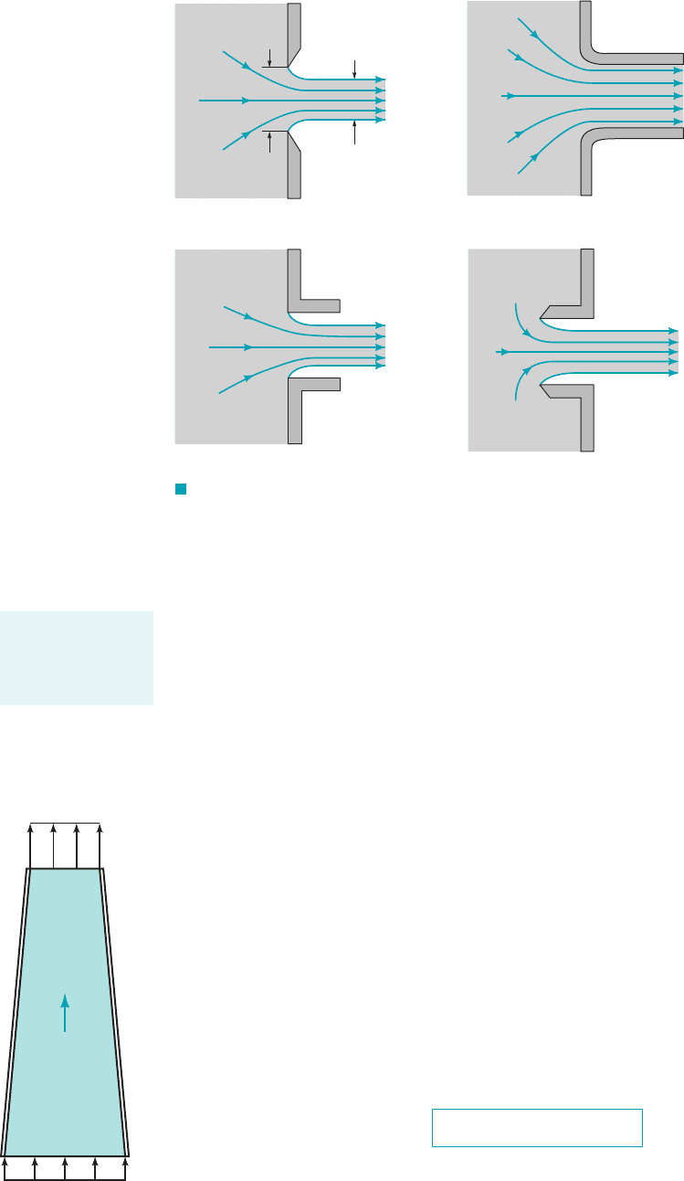
The vena contracta effect is a function of the geometry of the outlet. Some typical configu-
rations are shown in Fig. 3.14 along with typical values of the experimentally obtained contrac-
tion coefficient, where and are the areas of the jet at the vena contracta and the
area of the hole, respectively.
A
h
A
j
C
c
A
j
A
h
,
d
j
h,
p
1
p
3
0,
1r 02.
1r 6 2,
90°
d
h
.d
j
,
d h
V
3
,V
1
,
V
2
,
V 12gh,
3.6 Examples of Use of the Bernoulli Equation 111
V = 0
V = 2gh
h
h
(1)
(2)
V =
√2gh
F I G U R E 3.12 Horizontal flow from a tank.
F I G U R E 3.13 Vena
contracta effect for a sharp-edged orifice.
h
d
(1)
(2)
(3)
(
a)
d
j
d
h
(2)
(1)
(3)
a
a
h
d
(b)
Fluids in the News
Cotton candy, glass wool, and steel wool Although cotton candy
and glass wool insulation are made of entirely different materials
and have entirely different uses, they are made by similar processes.
Cotton candy, invented in 1897, consists of sugar fibers. Glass wool,
invented in 1938, consists of glass fibers. In a cotton candy machine,
sugar is melted and then forced by centrifugal action to flow through
numerous tiny orifices in a spinning “bowl.” Upon emerging, the
thin streams of liquid sugar cool very quickly and become solid
threads that are collected on a stick or cone. Making glass wool in-
sulation is somewhat more complex, but the basic process is similar.
Liquid glass is forced through tiny orifices and emerges as very fine
glass streams that quickly solidify. The resulting intertwined flexible
fibers, glass wool, form an effective insulation material because the
tiny air “cavities” between the fibers inhibit air motion. Although
steel wool looks similar to cotton candy or glass wool, it is made by
an entirely different process. Solid steel wires are drawn over special
cutting blades which have grooves cut into them so that long, thin
threads of steel are peeled off to form the matted steel wool.
The diameter of a
fluid jet is often
smaller than that of
the hole from
which it flows.
JWCL068_ch03_093-146.qxd 8/19/08 10:23 PM Page 111
3.6.2 Confined Flows
In many cases the fluid is physically constrained within a device so that its pressure cannot be pre-
scribed a priori as was done for the free jet examples above. Such cases include nozzles and pipes
of variable diameter for which the fluid velocity changes because the flow area is different from
one section to another. For these situations it is necessary to use the concept of conservation of
mass 1the continuity equation2along with the Bernoulli equation. The derivation and use of this
equation are discussed in detail in Chapters 4 and 5. For the needs of this chapter we can use a
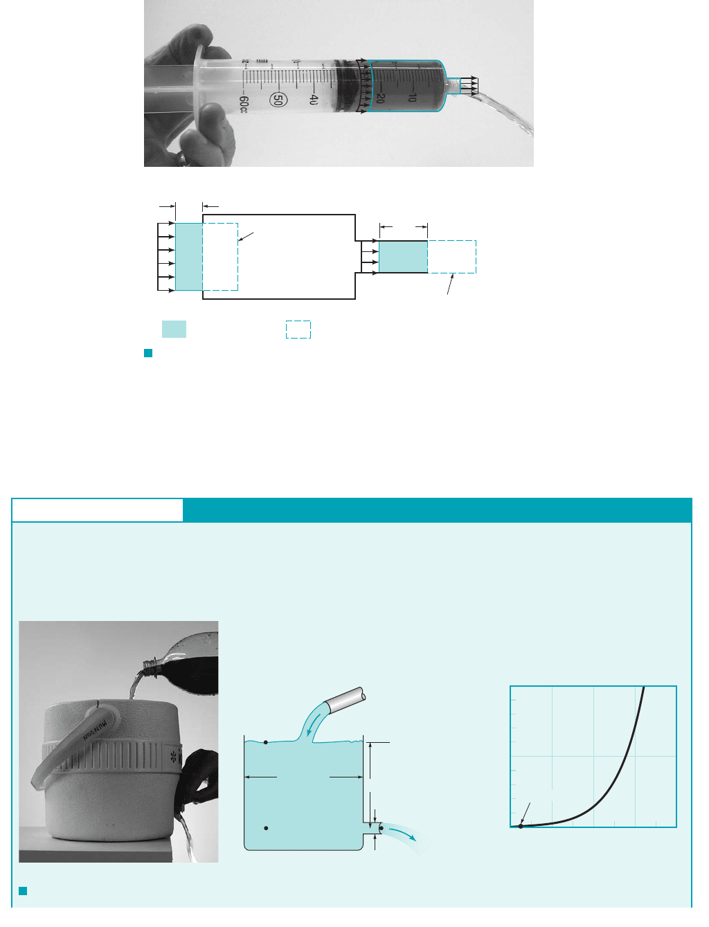
simplified form of the continuity equation obtained from the following intuitive arguments. Con-
sider a fluid flowing through a fixed volume 1such as a syringe2that has one inlet and one outlet
as shown in Fig. 3.15a. If the flow is steady so that there is no additional accumulation of fluid
within the volume, the rate at which the fluid flows into the volume must equal the rate at which
it flows out of the volume 1otherwise, mass would not be conserved2.
The mass flowrate from an outlet, 1slugss or kgs2, is given by where Q
is the volume flowrate. If the outlet area is A and the fluid flows across this area 1normal to the area2
with an average velocity V, then the volume of the fluid crossing this area in a time interval is
equal to that in a volume of length and cross-sectional area A 1see Fig. 3.15b2. Hence, the vol-
ume flowrate 1volume per unit time2is Thus, To conserve mass, the inflow rate
must equal the outflow rate. If the inlet is designated as 112and the outlet as 122, it follows that
Thus, conservation of mass requires
If the density remains constant, then and the above becomes the continuity equation for
incompressible flow
(3.19)
For example, if as shown by the figure in the margin the outlet flow area is one-half the size of the
inlet flow area, it follows that the outlet velocity is twice that of the inlet velocity, since
A
1
V
1
A
2
V
2
, or Q
1
Q
2
r
1
r
2
,
r
1
A
1
V
1
r
2
A
2
V
2
m
#
1
m
#
2
.
m
#
rVA.Q VA.
V dt
VA dt,dt
1ft
3
s or m
3
s2m
#
rQ,m
#
112 Chapter 3 ■ Elementary Fluid Dynamics—The Bernoulli Equation
d
h
d
j
C
C
= 0.61
C
C
= 0.61
C
C
= 0.50
C
C
= 1.0
C
C
= A
j
/A
h
= (d
j
/d
h
)
2
(a) Knife edge (b) Well rounded
(
c) Sharp edge (d) Re-entrant
F I G U R E 3.14 Typical flow patterns and contraction coefficients
for various round exit configurations. (a) Knife edge, (b) Well rounded, (c) Sharp
edge, (d) Re-entrant.
The continuity
equation states that
mass cannot be cre-
ated or destroyed.
A
2
Q
V
2
= 2V
1
V
1
A
1
= 2A
2
(1)
JWCL068_ch03_093-146.qxd 8/19/08 10:23 PM Page 112
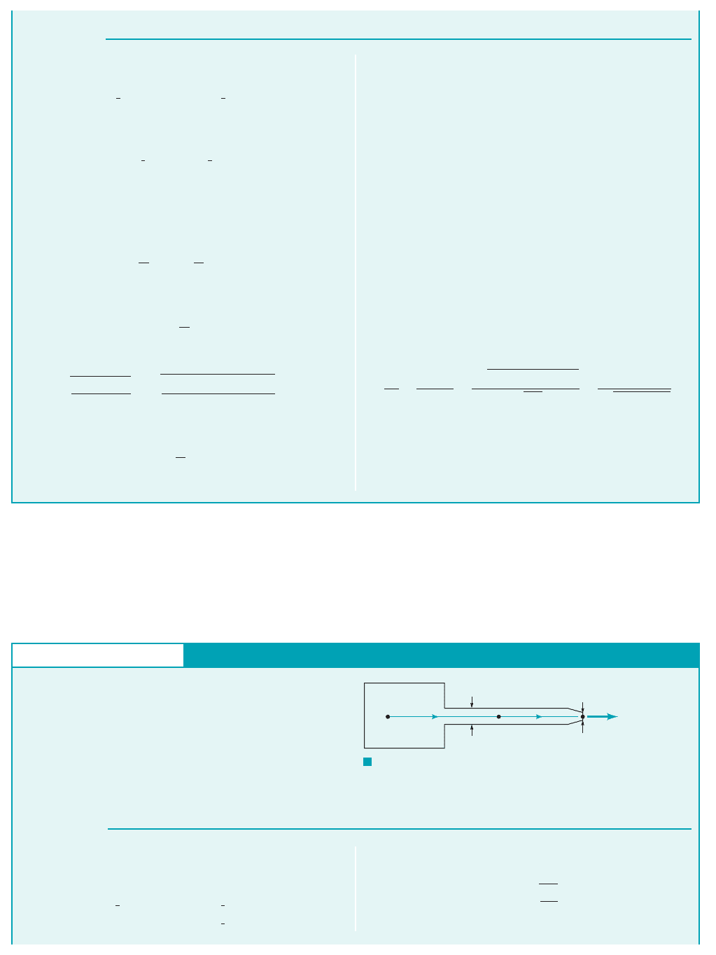
GIVEN A stream of refreshing beverage of diameter d⫽ 0.01 m
flows steadily from the cooler of diameter D ⫽ 0.20 m as shown
in Figs. E3.7a and b.
FIND Determine the flowrate, Q, from the bottle into the
cooler if the depth of beverage in the cooler is to remain constant
at h ⫽ 0.20 m
Flow from a Tank—Gravity
E
XAMPLE 3.7
3.6 Examples of Use of the Bernoulli Equation 113
V
1
(1)
Volume =
V
1
t A
1
V
2
(2)
Volume =
V
2
t A
2
Same parcel at t = tFluid parcel at t = 0
V
1
t
δ
δ
δ
V
2
t
δ
δ
V
1
V
2
(2)
(1)
F I G U R E 3.15 (a) Flow through a syringe. (b) Steady flow into
and out of a volume.
(a) (b)
d = 0.01 m
h = 0.20 m
D = 0.20 m
(1)
(2)
(3)
Q
1.10
1.05
1.00
0 0.2 0.4 0.6 0.8
d/D
Q
/Q
0
(c)
(0.05, 1.000003)
F I G U R E E3.7
The use of the Bernoulli equation and the flowrate equation 1continuity equa-
tion2is demonstrated by Example 3.7.
V
2
⫽ A
1
V
1
Ⲑ
A
2
⫽ 2V
1
.
JWCL068_ch03_093-146.qxd 9/30/08 6:46 PM Page 113
The fact that a kinetic energy change is often accompanied by a change in pressure is shown
by Example 3.8.
114 Chapter 3 ■ Elementary Fluid Dynamics—The Bernoulli Equation
For steady, inviscid, incompressible flow, the Bernoulli equation
applied between points 112and 122is
(1)
With the assumptions that and Eq. 1
becomes
(2)
Although the liquid level remains constant 1 constant2, there is an
average velocity, across section 112because of the flow from the
tank. From Eq. 3.19 for steady incompressible flow, conservation of
mass requires where Thus, or
Hence,
(3)
Equations 1 and 3 can be combined to give
Thus,
(Ans)
1.56 10
4
m
3
s
Q A
1
V
1
A
2
V
2
p
4
10.01 m2
2
11.98 m
s2
V
2
B
2gh
1 1d
D2
4
B
219.81 m
s
2
210.20 m2
1 10.01 m
0.20 m2
4
1.98 m
s
V
1
a
d
D
b
2
V
2
p
4
D
2
V
1
p
4
d
2
V
2
A
1
V
1
A
2
V
2
,Q AV.Q
1
Q
2
,
V
1
,
h
1
2
V
2
1
gh
1
2
V
2
2
z
2
0,p
1
p
2
0, z
1
h,
p
1
1
2
rV
2
1
gz
1
p
2
1
2
rV
2
2
gz
2
COMMENTS Note that this problem was solved using
points (1) and (2) located at the free surface and the exit of the
pipe, respectively. Although this was convenient (because most
of the variables are known at those points), other points could be
selected and the same result would be obtained. For example,
consider points (1) and (3) as indicated in Fig. E3.7b. At (3), lo-
cated sufficiently far from the tank exit, V
3
0 and z
3
z
2
0.
Also, p
3
h since the pressure is hydrostatic sufficiently far
from the exit. Use of this information in the Bernoulli equation
applied between (1) and (3) gives the exact same result as ob-
tained using it between (1) and (2). The only difference is that
the elevation head, z
1
h, has been interchanged with the pres-
sure head at (3), p
3
/ h.
In this example we have not neglected the kinetic energy of
the water in the tank If the tank diameter is large com-
pared to the jet diameter Eq. 3 indicates that
and the assumption that would be reasonable. The error
associated with this assumption can be seen by calculating the
ratio of the flowrate assuming denoted Q, to that as-
suming denoted This ratio, written as
is plotted in Fig. E3.7c. With it follows that
and the error in assuming is less than
1%. For this example with d/D 0.01 m/0.20 m 0.05, it follows
that Q/Q
0
1.000003. Thus, it is often reasonable to assume
V
1
0.
V
1
01 6 Q
Q
0
1.01,
0 6 d
D 6 0.4
Q
Q
0
V
2
V
2
0
D
22gh
31 1d
D2
4
4
22gh
1
21 1d
D2
4
Q
0
.V
1
0,
V
1
0,
V
1
0
V
1
V
2
1D d2,
1V
1
02.
S
OLUTION
GIVEN Air flows steadily from a tank, through a hose of di-
ameter and exits to the atmosphere from a nozzle of
diameter as shown in Fig. E3.8. The pressure in the
tank remains constant at 3.0 kPa 1gage2and the atmospheric con-
ditions are standard temperature and pressure.
FIND Determine the flowrate and the pressure in the hose.
d 0.01 m
D 0.03 m,
S
OLUTION
Flow from a Tank—Pressure
With the assumption that 1horizontal hose2,
1large tank2,and 1free jet2, this becomes
V
3
B
2p
1
r
p
3
0
V
1
0z
1
z
2
z
3
E
XAMPLE 3.8
If the flow is assumed steady, inviscid, and incompressible, we
can apply the Bernoulli equation along the streamline from (1) to
(2) to (3) as
p
3
1
2
rV
2
3
gz
3
p
1
1
2
rV
2
1
gz
1
p
2
1
2
rV
2
2
gz
2
p
1
= 3.0 kPa
(1)
Air
D = 0.03 m
(2)
(3)
d = 0.01 m
Q
F I G U R E E3.8
JWCL068_ch03_093-146.qxd 8/19/08 10:24 PM Page 114

In many situations the combined effects of kinetic energy, pressure, and gravity are important.
Example 3.9 illustrates this.
3.6 Examples of Use of the Bernoulli Equation 115
and
(1)
The density of the air in the tank is obtained from the perfect gas
law, using standard absolute pressure and temperature, as
Thus, we find that
or
(Ans)
The pressure within the hose can be obtained from Eq. 1 and
the continuity equation 1Eq. 3.192
Hence,
a
0.01 m
0.03 m
b
2
169.0 m
s2 7.67 m
s
V
2
A
3
V
3
A
2
a
d
D
b
2
V
3
A
2
V
2
A
3
V
3
0.00542 m
3
s
Q A
3
V
3
p
4
d
2
V
3
p
4
10.01 m2
2
169.0 m
s2
V
3
B
213.0 10
3
N
m
2
2
1.26 kg
m
3
69.0 m
s
1.26 kg
m
3
10
3
N
kN
1286.9 N
m
kg
K2115 2732K
313.0 1012 kN
m
2
4
r
p
1
RT
1
p
2
p
1
1
2
rV
2
2
and from Eq. 1
(Ans)
COMMENTS Notethatthe valueof isdeterminedstrictlyby
the value of 1and the assumptions involved in the Bernoulli equa-
tion2, independent of the “shape” of the nozzle. The pressure head
within the tank,
is converted to the velocity head at the exit,
Although we used gage
pressure in the Bernoulli equation we had to use
absolute pressure in the perfect gas law when calculating the
density.
In the absence of viscous effects the pressure throughout the
hose is constant and equal to Physically, the decreases in
pressure from to to accelerate the air and increase its
kinetic energy from zero in the tank to an intermediate value in
the hose and finally to its maximum value at the nozzle exit.
Since the air velocity in the nozzle exit is nine times that in the
hose, most of the pressure drop occurs across the nozzle
and
Since the pressure change from 112to 132is not too great
i.e., in terms of absolute pressure
it follows from the perfect gas law that the density change
is also not significant. Hence, the incompressibility assumption is
reasonable for this problem. If the tank pressure were consider-
ably larger or if viscous effects were important, the above results
would be incorrect.
0.034,
1p
1
p
3
2
p
1
3.0
101 3
p
3
02.N
m
2
,1p
1
3000 N
m
2
, p
2
2963
p
3
p
2
p
1
p
2
.
1p
3
02,
169.0 m
s2
2
12 9.81 m
s
2
2 243 m.
V
2
2
2g 243 m,
p
1
g 13.0 kPa2
19.81 m
s
2
211.26 kg
m
3
2
p
1
V
3
13000 37.12N
m
2
2963 N
m
2
p
2
3.0 10
3
N
m
2
1
2
11.26 kg
m
3
217.67 m
s2
2
Fluids in the News
Hi-tech inhaler The term inhaler often brings to mind a treat-
ment for asthma or bronchitis. Work is underway to develop a
family of inhalation devices that can do more than treat respira-
tory ailments. They will be able to deliver medication for
diabetes and other conditions by spraying it to reach the blood-
stream through the lungs. The concept is to make the spray
droplets fine enough to penetrate to the lungs’ tiny sacs, the
alveoli, where exchanges between blood and the outside world
take place. This is accomplished by use of a laser-machined
nozzle containing an array of very fine holes that cause the
liquid to divide into a mist of micron-scale droplets. The device
fits the hand and accepts a disposable strip that contains the
medicine solution sealed inside a blister of laminated plastic and
the nozzle. An electrically actuated piston drives the liquid from
its reservoir through the nozzle array and into the respiratory
system. To take the medicine, the patient breathes through the
device and a differential pressure transducer in the inhaler
senses when the patient’s breathing has reached the best condi-
tion for receiving the medication. At that point, the piston is au-
tomatically triggered.
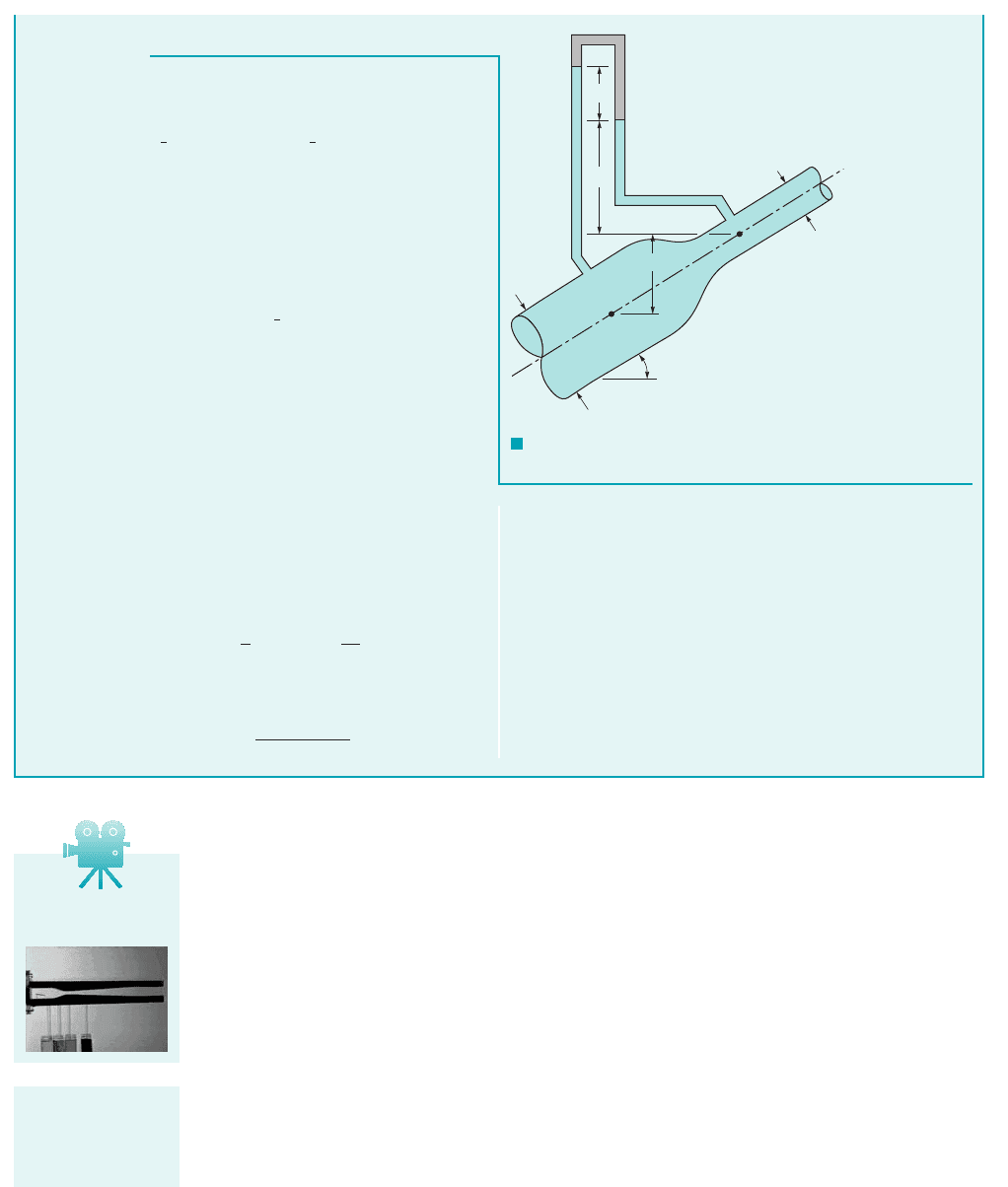
GIVEN Water flows through a pipe reducer as is shown in Fig.
E3.9. The static pressures at 112and 122are measured by the in-
verted U-tube manometer containing oil of specific gravity, SG,
less than one.
Flow in a Variable Area Pipe
E
XAMPLE 3.9
FIND Determine the manometer reading, h.
JWCL068_ch03_093-146.qxd 8/19/08 10:25 PM Page 115
In general, an increase in velocity is accompanied by a decrease in pressure. For example,
the velocity of the air flowing over the top surface of an airplane wing is, on the average, faster
than that flowing under the bottom surface. Thus, the net pressure force is greater on the bottom
than on the top—the wing generates a lift.
If the differences in velocity are considerable, the differences in pressure can also be con-
siderable. For flows of gases, this may introduce compressibility effects as discussed in Section
3.8 and Chapter 11. For flows of liquids, this may result in cavitation, a potentially dangerous sit-
uation that results when the liquid pressure is reduced to the vapor pressure and the liquid “boils.”
As discussed in Chapter 1, the vapor pressure, p
v
, is the pressure at which vapor bubbles form
in a liquid. It is the pressure at which the liquid starts to boil. Obviously this pressure depends on
the type of liquid and its temperature. For example, water, which boils at at standard
atmospheric pressure, 14.7 psia, boils at if the pressure is 0.507 psia. That is, psia
at and psia at 1See Tables B.1 and B.2.2
One way to produce cavitation in a flowing liquid is noted from the Bernoulli equation. If the
fluid velocity is increased 1for example, by a reduction in flow area as shown in Fig. 3.162the pres-
sure will decrease. This pressure decrease 1needed to accelerate the fluid through the constriction2
can be large enough so that the pressure in the liquid is reduced to its vapor pressure. A simple ex-
ample of cavitation can be demonstrated with an ordinary garden hose. If the hose is “kinked,” a
restriction in the flow area in some ways analogous to that shown in Fig. 3.16 will result. The water
velocity through this restriction will be relatively large. With a sufficient amount of restriction the
sound of the flowing water will change—a definite “hissing” sound is produced. This sound is a
result of cavitation.
212 °F.p
v
14.780 °F
p
v
0.50780 °F
212 °F
116 Chapter 3 ■ Elementary Fluid Dynamics—The Bernoulli Equation
S
OLUTION
COMMENT
The difference in elevation, was not
needed because the change in elevation term in the Bernoulli
equation exactly cancels the elevation term in the manometer
equation. However, the pressure difference, depends on
the angle because of the elevation, in Eq. 1. Thus, for a
given flowrate, the pressure difference, as measured by a
pressure gage would vary with but the manometer reading, h,
would be independent of u.
u,
p
1
p
2
,
z
1
z
2
,u,
p
1
p
2
,
z
1
z
2
,
With the assumptions of steady, inviscid, incompressible flow, the
Bernoulli equation can be written as
The continuity equation 1Eq. 3.192provides a second relationship
between and if we assume the velocity profiles are uniform
at those two locations and the fluid incompressible:
By combining these two equations we obtain
(1)
This pressure difference is measured by the manometer and can
be determined by using the pressure–depth ideas developed in
Chapter 2. Thus,
or
(2)
As discussed in Chapter 2, this pressure difference is neither
merely nor
Equations 1 and 2 can be combined to give the desired result
as follows:
or since
(Ans)
h 1Q
A
2
2
2
1 1A
2
A
1
2
2
2g11 SG2
V
2
Q
A
2
11 SG2gh
1
2
rV
2
2
c1 a
A
2
A
1
b
2
d
g1h z
1
z
2
2.gh
p
1
p
2
g1z
2
z
1
2 11 SG2gh
p
1
g
1z
2
z
1
2 g/ gh SG gh g/ p
2
p
1
p
2
g1z
2
z
1
2
1
2
rV
2
2
31 1A
2
A
1
2
2
4
Q A
1
V
1
A
2
V
2
V
2
V
1
p
1
1
2
rV
2
1
gz
1
p
2
1
2
rV
2
2
gz
2
F I G U R E E3.9
γ
(1)
z
2
– z
1
(2)
Water
θ
D
1
D
2
h
SG
V3.10 Venturi
channel
Cavitation occurs
when the pressure
is reduced to the
vapor pressure.
JWCL068_ch03_093-146.qxd 8/19/08 10:25 PM Page 116