Munson B.R. Fundamentals of Fluid Mechanics
Подождите немного. Документ загружается.

2.10 Hydrostatic Force on a Curved Surface 67
F I G U R E 2.23 Hydrostatic
force on a curved surface.
CG
O
C
AB
F
H
F
V
F
2
F
1
ᐃ
A
C
B
(b)(c)(d)
O
B
C
√(F
H
)
2
+ (F
V
)
2
F
R
=
(a)
The resultant passes through the point O, which can be located by summing moments about an
appropriate axis. The resultant force of the fluid acting on the curved surface BC is equal and op-
posite in direction to that obtained from the free-body diagram of Fig. 2.23c. The desired fluid
force is shown in Fig. 2.23d.
F
R
Hydrostatic Pressure Force on a Curved Surface
E
XAMPLE 2.9
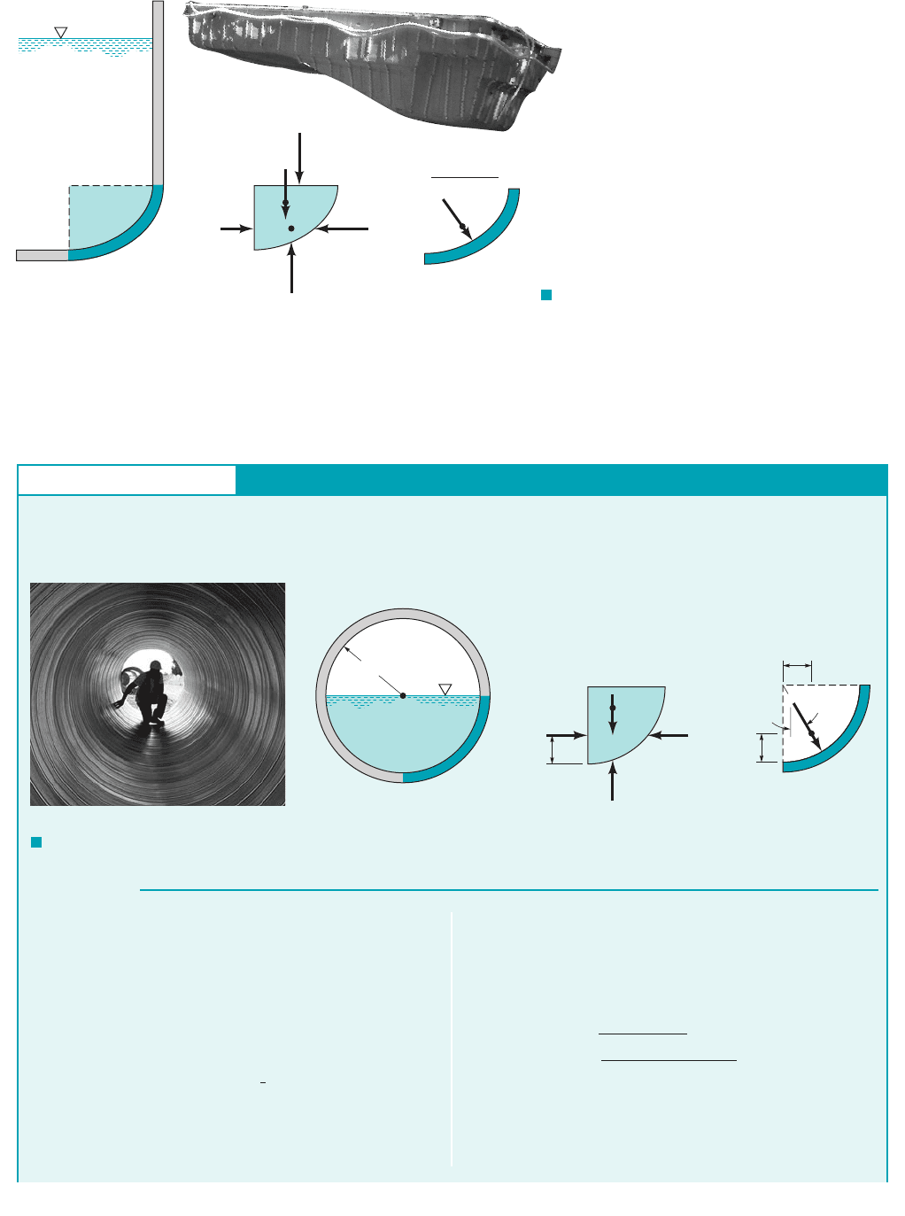
GIVEN A 6-ft-diameter drainage conduit of the type shown in
Fig. E2.9a is half full of water at rest, as shown in Fig. E2.9b.
FIND Determine the magnitude and line of action of the resul-
tant force that the water exerts on a 1-ft length of the curved sec-
tion BC of the conduit wall.
S
OLUTION
F I G U R E E2.9 (Photograph courtesy of CONTECH Construction Products, Inc.)
B
C
(b)
AB
C
F
V
F
H
F
1
1 ft
ᐃ
CG
(
c)
1 ft
A
1.27 ft
O
F
R
= 523 lb
32.5°
(d)
3 ft
A
(a)
We first isolate a volume of fluid bounded by the curved section
BC, the horizontal surface AB, and the vertical surface AC,as
shown in Fig. E2.9c. The volume has a length of 1 ft. The forces
acting on the volume are the horizontal force, which acts on
the vertical surface AC, the weight, of the fluid contained
within the volume, and the horizontal and vertical components of
the force of the conduit wall on the fluid, respectively.
The magnitude of is found from the equation
and this force acts 1 ft above C as shown. The weight ,
where is the fluid volume, is
w g V162.4 lb
ft
3
2
19p
4 ft
2
2
11 ft2 441 lb
V
w gV
F
1
gh
c
A 162.4 lb
ft
3
2
1
3
2
ft2 13 ft
2
2 281 lb
F
1
F
H
and F
V
,
w,
F
1
,
and acts through the center of gravity of the mass of fluid, which
according to Fig. 2.18 is located 1.27 ft to the right of AC as
shown. Therefore, to satisfy equilibrium
and the magnitude of the resultant force is
(Ans)
The force the water exerts on the conduit wall is equal, but oppo-
site in direction, to the forces shown in Fig. E2.9c.
Thus, the resultant force on the conduit wall is shown in
Fig. E2.9d. This force acts through the point O at the angle shown.
F
H
and F
V
21281 lb2
2
1441 lb2
2
523 lb
F
R
21F
H
2
2
1F
V
2
2
F
H
F
1
281 lb
F
V
w 441 lb
JWCL068_ch02_038-092.qxd 8/19/08 10:15 PM Page 67

This same general approach can also be used for determining the force on curved surfaces
of pressurized, closed tanks. If these tanks contain a gas, the weight of the gas is usually negli-
gible in comparison with the forces developed by the pressure. Thus, the forces 1such as
in Fig. 2.23c2on horizontal and vertical projections of the curved surface of interest can simply
be expressed as the internal pressure times the appropriate projected area.
F
1
and F
2
68 Chapter 2 ■ Fluid Statics
2.11.1 Archimedes’ Principle
When a stationary body is completely submerged in a fluid 1such as the hot air balloon shown in
the figure in the margin2, or floating so that it is only partially submerged, the resultant fluid force
acting on the body is called the buoyant force. A net upward vertical force results because pres-
sure increases with depth and the pressure forces acting from below are larger than the pressure
forces acting from above. This force can be determined through an approach similar to that used
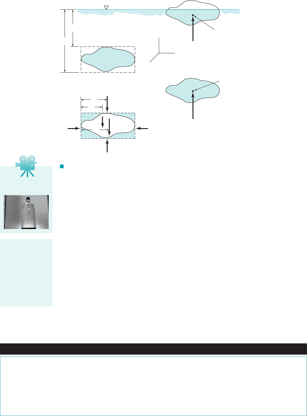
in the previous section for forces on curved surfaces. Consider a body of arbitrary shape, having
a volume that is immersed in a fluid as illustrated in Fig. 2.24a. We enclose the body in a par-
allelepiped and draw a free-body diagram of the parallelepiped with the body removed as shown
in Fig. 2.24b. Note that the forces and are simply the forces exerted on the plane
surfaces of the parallelepiped 1for simplicity the forces in the x direction are not shown2, is the
weight of the shaded fluid volume 1parallelepiped minus body2, and is the force the body is
exerting on the fluid. The forces on the vertical surfaces, such as are all equal and can-
cel, so the equilibrium equation of interest is in the z direction and can be expressed as
(2.21)
If the specific weight of the fluid is constant, then
where A is the horizontal area of the upper 1or lower2surface of the parallelepiped, and Eq. 2.21
can be written as
Simplifying, we arrive at the desired expression for the buoyant force
(2.22)F
B
g V
F
B
g1h
2
h
1
2A g 31h
2
h
1
2A V 4
F
2
F
1
g1h
2
h
1
2A
F
B
F
2
F
1
w
F
3
and F
4
,
F
B
w
F
4
F
1
, F
2
, F
3
,
V,
2.11 Buoyancy, Flotation, and Stability
(Photograph courtesy of
Cameron Balloons.)
COMMENT An inspection of this result will show that the line
of action of the resultant force passes through the center of the con-
duit. In retrospect, this is not a surprising result since at each point
on the curved surface of the conduit the elemental force due to the
pressure is normal to the surface, and each line of action must pass
through the center of the conduit. It therefore follows that the resul-
tant of this concurrent force system must also pass through the cen-
ter of concurrence of the elemental forces that make up the system.
Fluids in the News
Miniature, exploding pressure vessels Our daily lives are safer
because of the effort put forth by engineers to design safe, light-
weight pressure vessels such as boilers, propane tanks, and pop
bottles. Without proper design, the large hydrostatic pressure
forces on the curved surfaces of such containers could cause the
vessel to explode with disastrous consequences. On the other
hand, the world is a more friendly place because of miniature pres-
sure vessels that are designed to explode under the proper condi-
tions—popcorn kernels. Each grain of popcorn contains a small
amount of water within the special, impervious hull (pressure ves-
sel) which, when heated to a proper temperature, turns to steam,
causing the kernel to explode and turn itself inside out. Not all
popcorn kernels have the proper properties to make them pop well.
First, the kernel must be quite close to 13.5% water. With too little
moisture, not enough steam will build up to pop the kernel; too
much moisture causes the kernel to pop into a dense sphere rather
than the light fluffy delicacy expected. Second, to allow the pres-
sure to build up, the kernels must not be cracked or damaged.
V2.6 Atmospheric
buoyancy
JWCL068_ch02_038-092.qxd 8/19/08 10:16 PM Page 68
2.11 Buoyancy, Flotation, and Stability 69
where is the specific weight of the fluid and is the volume of the body. The direction of the
buoyant force, which is the force of the fluid on the body, is opposite to that shown on the free-
body diagram. Therefore, the buoyant force has a magnitude equal to the weight of the fluid dis-
placed by the body and is directed vertically upward. This result is commonly referred to as
Archimedes’ principle in honor of Archimedes 1287–212 B.C.2, a Greek mechanician and mathe-
matician who first enunciated the basic ideas associated with hydrostatics.
The location of the line of action of the buoyant force can be determined by summing moments
of the forces shown on the free-body diagram in Fig. 2.24b with respect to some convenient axis. For
example, summing moments about an axis perpendicular to the paper through point D we have
and on substitution for the various forces
(2.23)
where is the total volume The right-hand side of Eq. 2.23 is the first
moment of the displaced volume with respect to the x–z plane so that is equal to the y co-
ordinate of the centroid of the volume In a similar fashion it can be shown that the x coordi-
nate of the buoyant force coincides with the x coordinate of the centroid. Thus, we conclude that
the buoyant force passes through the centroid of the displaced volume as shown in Fig. 2.24c.
The point through which the buoyant force acts is called the center of buoyancy.
V.
y
c
V
1h
2
h
1
2A.V
T
Vy
c
V
T
y
1
1V
T
V2 y
2
F
B
y
c
F
2
y
1
F
1
y
1
wy
2
Vg
F I G U R E 2.24 Buoyant force on submerged and floating bodies.
h
2
h
1
AB
CD
AB
CD
(a)
(
b)
(
c)
(
d)
x
y
z
y
1
y
2
y
c
F
3
F
4
F
B
F
B
F
B
c
F
2
F
1
ᐃ
Centroid
Centroid
of displaced
volume
c
Archimedes’princi-
ple states that the
buoyant force has a
magnitude equal to
the weight of the
fluid displaced by
the body and is
directed vertically
upward.
Fluids in the News
Concrete canoes A solid block of concrete thrown into a pond or
lake will obviously sink. But, if the concrete is formed into the
shape of a canoe it can be made to float. Of course the reason the
canoe floats is the development of the buoyant force due to the
displaced volume of water. With the proper design, this vertical
force can be made to balance the weight of the canoe plus passen-
gers—the canoe floats. Each year since 1988 there is a National
Concrete Canoe Competition for university teams. It’s jointly
sponsored by the American Society of Civil Engineers and Master
Builders Inc. The canoes must be 90% concrete and are typically
designed with the aid of a computer by civil engineering students.
Final scoring depends on four components: a design report, an
oral presentation, the final product, and racing. For the 2007 com-
petition the University of Wisconsin’s team won for its fifth con-
secutive national championship with a 179-lb, 19.11-ft canoe.
(See Problem 2.107.)
V2.7 Cartesian
Diver
JWCL068_ch02_038-092.qxd 8/19/08 10:16 PM Page 69
70 Chapter 2 ■ Fluid Statics
These same results apply to floating bodies which are only partially submerged, as illustrated
in Fig. 2.24d, if the specific weight of the fluid above the liquid surface is very small compared
with the liquid in which the body floats. Since the fluid above the surface is usually air, for prac-
tical purposes this condition is satisfied.
In the derivations presented above, the fluid is assumed to have a constant specific weight,
If a body is immersed in a fluid in which varies with depth, such as in a layered fluid, the
magnitude of the buoyant force remains equal to the weight of the displaced fluid. However, the
buoyant force does not pass through the centroid of the displaced volume, but rather, it passes
through the center of gravity of the displaced volume.
gg.
V2.8 Hydrometer
Buoyant Force on a Submerged Object
E
XAMPLE 2.10
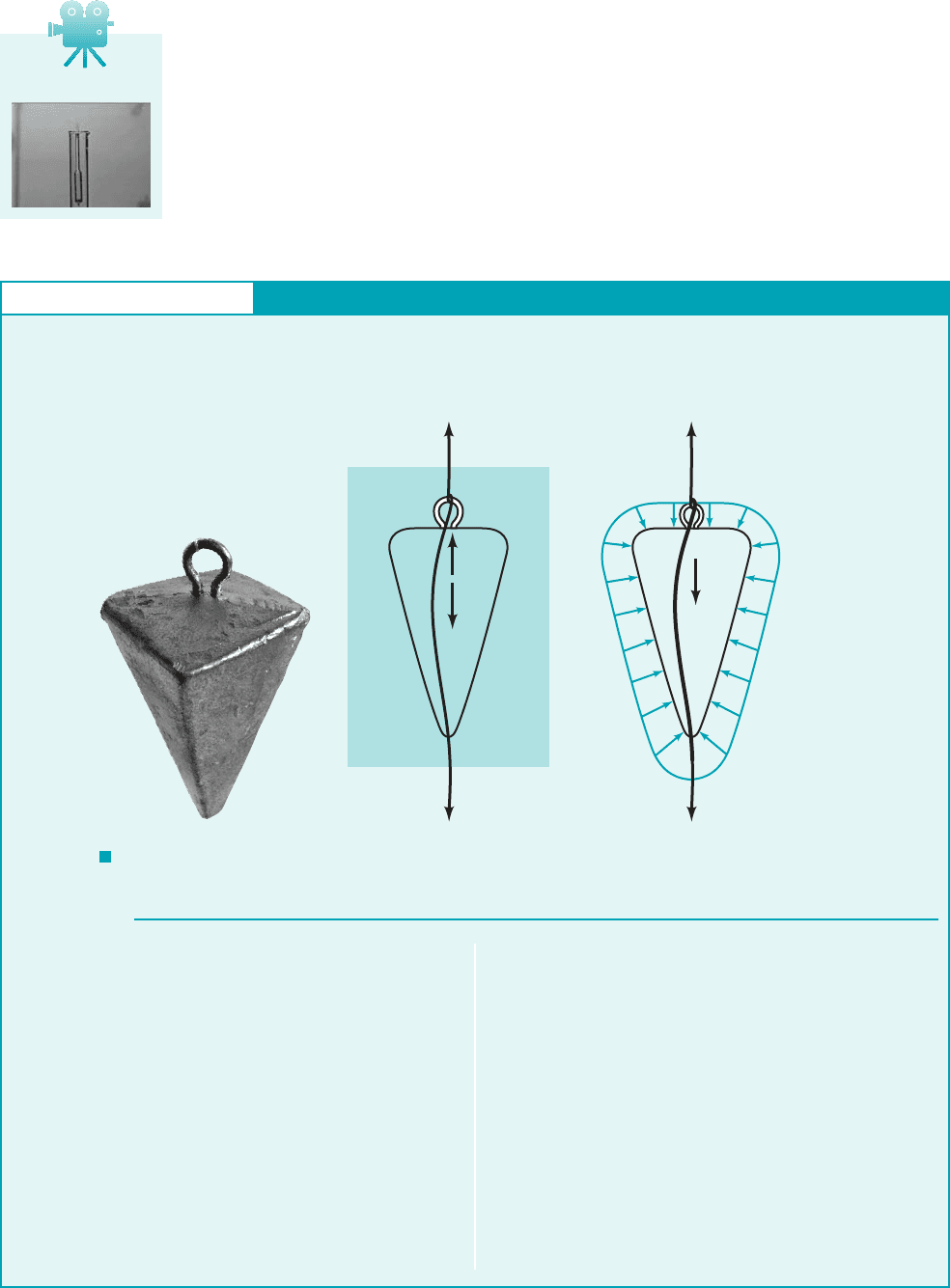
GIVEN The 0.4-lb lead fish sinker shown in Fig. E2.10a is at-
tached to a fishing line as shown in Fig. E2.10b. The specific
gravity of the sinker is SG
sinker
11.3.
FIND Determine the difference between the tension in the line
above and below the sinker.
S
OLUTION
A free body diagram of the sinker is shown in Fig. E.10b, where
is the weight of the sinker, F
B
is the buoyant force acting on the
sinker, and T
A
and T
B
are the tensions in the line above and below
the sinker, respectively. For equilibrium it follows that
(1)
Also,
(2)
where is the specific weight of water and is the volume of the
sinker. From Eq. 2.22,
(3)
By combining Eqs. 2 and 3 we obtain
(4)F
B
w
SG
sinker
F
B
gV
Vg
w g
sinker
VgSG
sinker
V
T
A
T
B
w F
B
w
Hence, from Eqs. 1 and 4 the difference in the tensions is
(5)
(Ans)
COMMENTS Note that if the sinker were raised out of the
water, the difference in tension would equal the entire weight of
the sinker (T
A
T
B
0.4 lb) rather than the 0.365 lb when it is
in the water. Thus, since the sinker material is significantly heav-
ier than water, the buoyant force is relatively unimportant. As
seen from Eq. 5, as SG
sinker
becomes very large, the buoyant force
becomes insignificant, and the tension difference becomes nearly
equal to the weight of the sinker. On the other hand, if SG
sinker
1,
then T
A
T
B
0 and the sinker is no longer a “sinker.” It is neu-
trally buoyant and no external force from the line is required to
hold it in place.
0.4 lb 31 11
11.324 0.365 lb
T
A
T
B
w w
SG
sinker
w31 11
SG
sinker
24
F I G U R E E2.10
(a)
ᐃ
F
B
T
A
T
B
Pressure
envelope
ᐃ
T
B
(b)(c)
T
A
JWCL068_ch02_038-092.qxd 8/19/08 10:16 PM Page 70
2.11 Buoyancy, Flotation, and Stability 71
2.11.2 Stability
Another interesting and important problem associated with submerged or floating bodies is con-
cerned with the stability of the bodies. As illustrated by the figure in the margin, a body is said to
be in a stable equilibrium position if, when displaced, it returns to its equilibrium position. Con-
versely, it is in an unstable equilibrium position if, when displaced 1even slightly2, it moves to a
new equilibrium position. Stability considerations are particularly important for submerged or float-
ing bodies since the centers of buoyancy and gravity do not necessarily coincide. A small rotation
can result in either a restoring or overturning couple. For example, for the completely submerged
body shown in Fig. 2.25, which has a center of gravity below the center of buoyancy, a rotation
from its equilibrium position will create a restoring couple formed by the weight, and the buoy-
ant force, which causes the body to rotate back to its original position. Thus, for this configu-
ration the body is stable. It is to be noted that as long as the center of gravity falls below the cen-
ter of buoyancy, this will always be true; that is, the body is in a stable equilibrium position with
respect to small rotations. However, as is illustrated in Fig. 2.26, if the center of gravity of the
completely submerged body is above the center of buoyancy, the resulting couple formed by the
weight and the buoyant force will cause the body to overturn and move to a new equilibrium po-
sition. Thus, a completely submerged body with its center of gravity above its center of buoyancy
is in an unstable equilibrium position.
For floating bodies the stability problem is more complicated, since as the body rotates the
location of the center of buoyancy 1which passes through the centroid of the displaced volume2may
F
B
,
w,
Stable
Unstable
The stability of a
body can be deter-
mined by consider-
ing what happens
when it is displaced
from its equilibrium
position.
F I G U R E 2.25
Stability of a completely immersed
body—center of gravity below
centroid.
F I G U R E 2.26
Stability of a completely immersed
body—center of gravity above
centroid.
F
B
F
B
cc
CG CG
ᐃᐃ
Restoring
couple
Stable
F
B
F
B
cc
CG CG
ᐃᐃ
Overturning
couple
Unstable
In this example we replaced the hydrostatic pressure force on the body by the buoyant force,
F
B
. Another correct free-body diagram of the sinker is shown in Fig. E2.20c. The net effect of
the pressure forces on the surface of the sinker is equal to the upward force of magnitude F
B
(the
buoyant force). Do not include both the buoyant force and the hydrostatic pressure effects in your
calculations—use one or the other.
Fluids in the News
Explosive Lake In 1986 a tremendous explosion of carbon diox-
ide (CO
2
) from Lake Nyos, west of Cameroon, killed more than
1700 people and livestock. The explosion resulted from a build up
of CO
2
that seeped into the high pressure water at the bottom of the
lake from warm springs of CO
2
-bearing water. The CO
2
-rich water
is heavier than pure water and can hold a volume of CO
2
more than
five times the water volume. As long as the gas remains dissolved
in the water, the stratified lake (i.e., pure water on top, CO
2
water
on the bottom) is stable. But if some mechanism causes the gas
bubbles to nucleate, they rise, grow, and cause other bubbles to
form, feeding a chain reaction. A related phenomenon often occurs
when a pop bottle is shaken and then opened. The pop shoots from
the container rather violently. When this set of events occurred in
Lake Nyos, the entire lake overturned through a column of rising
and expanding buoyant bubbles. The heavier-than-air CO
2
then
flowed through the long, deep valleys surrounding the lake and as-
phyxiated human and animal life caught in the gas cloud. One vic-
tim was 27 km downstream from the lake.
V2.9 Stability of a
floating cube
JWCL068_ch02_038-092.qxd 8/19/08 10:16 PM Page 71
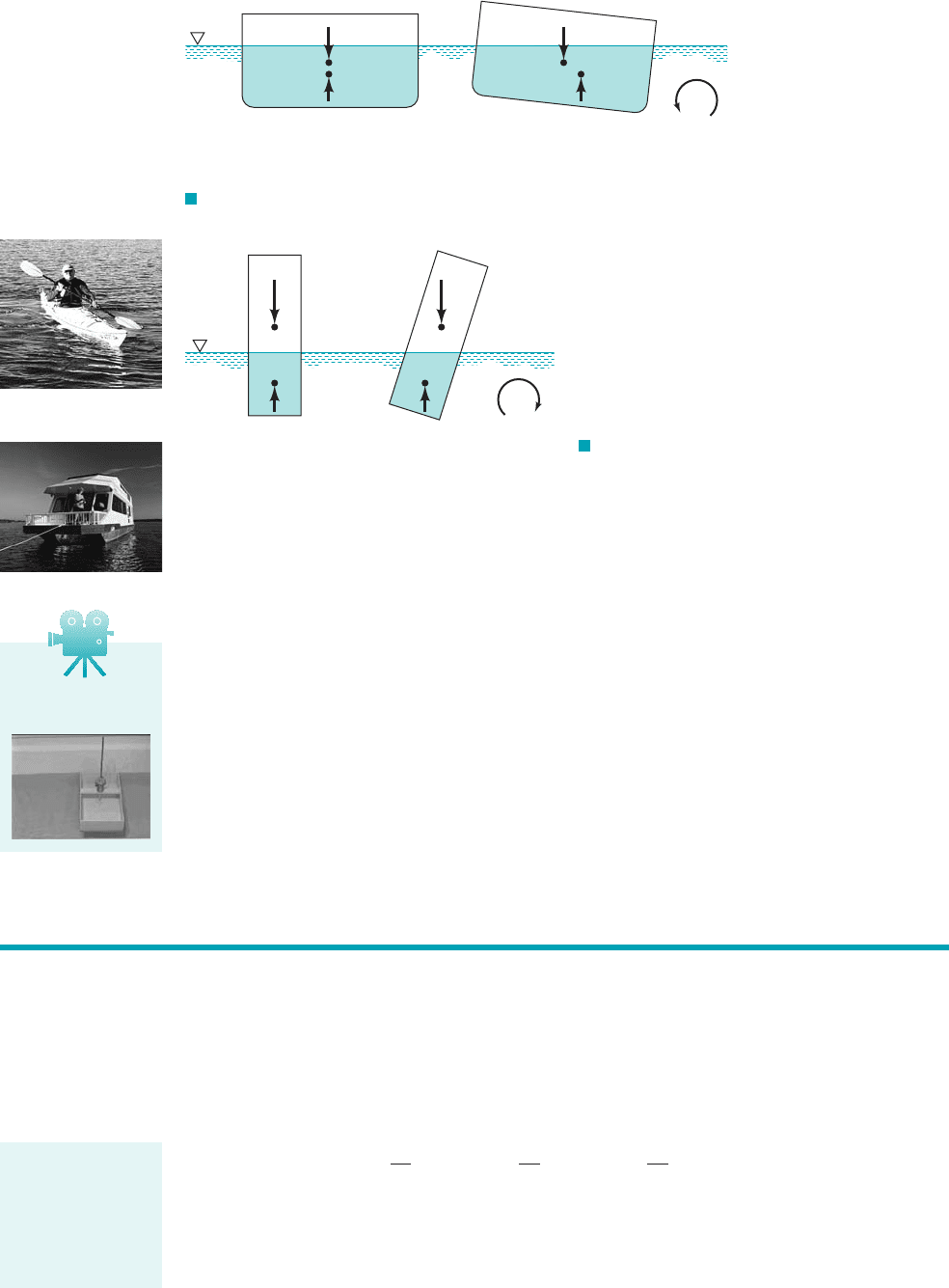
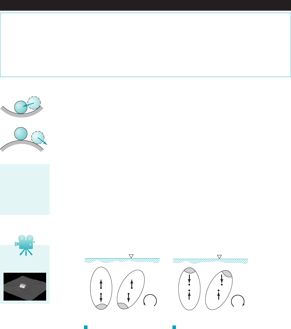
change. As is shown in Fig. 2.27, a floating body such as a barge that rides low in the water can be
stable even though the center of gravity lies above the center of buoyancy. This is true since as the
body rotates the buoyant force, shifts to pass through the centroid of the newly formed displaced
volume and, as illustrated, combines with the weight, to form a couple which will cause the
body to return to its original equilibrium position. However, for the relatively tall, slender body
shown in Fig. 2.28, a small rotational displacement can cause the buoyant force and the weight to
form an overturning couple as illustrated.
It is clear from these simple examples that the determination of the stability of submerged or
floating bodies can be difficult since the analysis depends in a complicated fashion on the particular
geometry and weight distribution of the body. Thus, although both the relatively narrow kayak and
the wide houseboat shown in the figures in the margin are stable, the kayak will overturn much more
easily than the houseboat. The problem can be further complicated by the necessary inclusion of other
types of external forces such as those induced by wind gusts or currents. Stability considerations are
obviously of great importance in the design of ships, submarines, bathyscaphes, and so forth, and
such considerations play a significant role in the work of naval architects 1see, for example, Ref. 62.
w,
F
B
,
72 Chapter 2 ■ Fluid Statics
F I G U R E 2.27 Stability of a floating body—stable configuration.
ᐃ
F
B
c
CG
Restoring
couple
c' = centroid of new
displaced volume
c = centroid of original
displaced volume
Stable
ᐃ
F
B
c'
CG
F I G U R E 2.28 Stability of a
floating body—unstable configuration.
ᐃ
ᐃ
CGCG
cc'
F
B
F
B
Overturning
couple
c' = centroid of new
displaced volume
c = centroid of original
displaced volume
Unstable
Although in this chapter we have been primarily concerned with fluids at rest, the general equa-
tion of motion 1Eq. 2.22
was developed for both fluids at rest and fluids in motion, with the only stipulation being that there
were no shearing stresses present. Equation 2.2 in component form, based on rectangular coordi-
nates with the positive z axis being vertically upward, can be expressed as
(2.24)
A general class of problems involving fluid motion in which there are no shearing stresses
occurs when a mass of fluid undergoes rigid-body motion. For example, if a container of fluid ac-
celerates along a straight path, the fluid will move as a rigid mass 1after the initial sloshing mo-
tion has died out2with each particle having the same acceleration. Since there is no deformation,
0p
0x
ra
x
0p
0y
ra
y
0p
0z
g ra
z
§p gk
ˆ
ra
2.12 Pressure Variation in a Fluid with Rigid-Body Motion
Marginally stable
Very stable
Even though a fluid
may be in motion, if
it moves as a rigid
body there will be
no shearing
stresses present.
V2.10 Stability of a
model barge
JWCL068_ch02_038-092.qxd 8/19/08 10:16 PM Page 72
2.12 Pressure Variation in a Fluid with Rigid-Body Motion 73
there will be no shearing stresses and, therefore, Eq. 2.2 applies. Similarly, if a fluid is contained
in a tank that rotates about a fixed axis, the fluid will simply rotate with the tank as a rigid body,
and again Eq. 2.2 can be applied to obtain the pressure distribution throughout the moving fluid.
Specific results for these two cases 1rigid-body uniform motion and rigid-body rotation2are devel-
oped in the following two sections. Although problems relating to fluids having rigid-body motion
are not, strictly speaking, “fluid statics” problems, they are included in this chapter because, as we
will see, the analysis and resulting pressure relationships are similar to those for fluids at rest.
2.12.1 Linear Motion
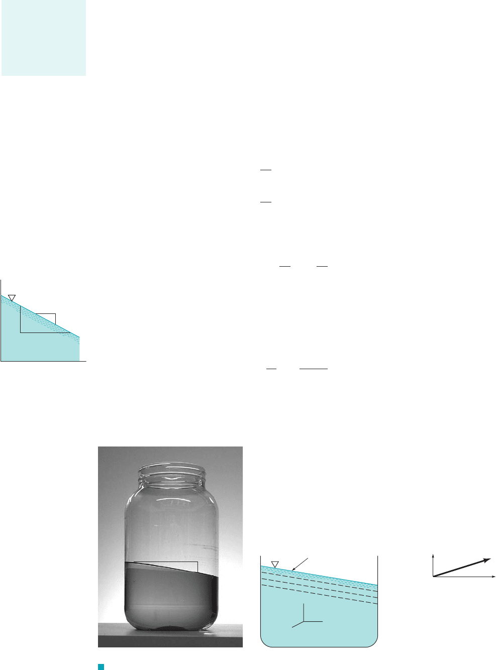
We first consider an open container of a liquid that is translating along a straight path with a constant
acceleration a as illustrated in Fig. 2.29. Since , it follows from the first of Eqs. 2.24 that the
pressure gradient in the x direction is zero In the y and z directions
(2.25)
(2.26)
The change in pressure between two closely spaced points located at y, z, and can
be expressed as
or in terms of the results from Eqs. 2.25 and 2.26
(2.27)
Along a line of constant pressure, and therefore from Eq. 2.27 it follows that the slope of
this line is given by the relationship
(2.28)
This relationship is illustrated by the figure in the margin. Along a free surface the pressure is con-
stant, so that for the accelerating mass shown in Fig. 2.29 the free surface will be inclined if
In addition, all lines of constant pressure will be parallel to the free surface as illustrated.
a
y
0.
dz
dy
a
y
g a
z
dp 0,
dp ra
y
dy r1g a
z
2 dz
dp
0p
0y
dy
0p
0z
dz
y dy, z dz
0p
0z
r1g a
z
2
0p
0y
ra
y
10p
0x 02.
a
x
0
z
dz
dy
a
y
y
g + a
z
a
y
g
(a)
F I G U R E 2.29 Linear acceleration of a liquid with a free surface.
Free surface
slope =
dz/dy
p
1
p
2
p
3
a
z
a
y
y
z
x
Constant
pressure
lines
a
(
b)
(
c)
There is no shear
stress in fluids that
move with rigid-
body motion or
with rigid-body
rotation.
JWCL068_ch02_038-092.qxd 8/19/08 10:16 PM Page 73
74 Chapter 2 ■ Fluid Statics
For the special circumstance in which which corresponds to the mass of
fluid accelerating in the vertical direction, Eq. 2.28 indicates that the fluid surface will be hor-
izontal. However, from Eq. 2.26 we see that the pressure distribution is not hydrostatic, but is
given by the equation
For fluids of constant density this equation shows that the pressure will vary linearly with depth,
but the variation is due to the combined effects of gravity and the externally induced acceleration,
rather than simply the specific weight Thus, for example, the pressure along the bot-
tom of a liquid-filled tank which is resting on the floor of an elevator that is accelerating upward
will be increased over that which exists when the tank is at rest 1or moving with a constant veloc-
ity2. It is to be noted that for a freely falling fluid mass the pressure gradients in all
three coordinate directions are zero, which means that if the pressure surrounding the mass is zero,
the pressure throughout will be zero. The pressure throughout a “blob” of orange juice floating in
an orbiting space shuttle 1a form of free fall2is zero. The only force holding the liquid together is
surface tension 1see Section 1.92.
1a
z
g2,
rg.r1g a
z
2,
dp
dz
r 1g a
z
2
a
y
0, a
z
0,
The pressure distri-
bution in a fluid
mass that is accel-
erating along a
straight path is not
hydrostatic.
Pressure Variation in an Accelerating Tank
E
XAMPLE 2.11
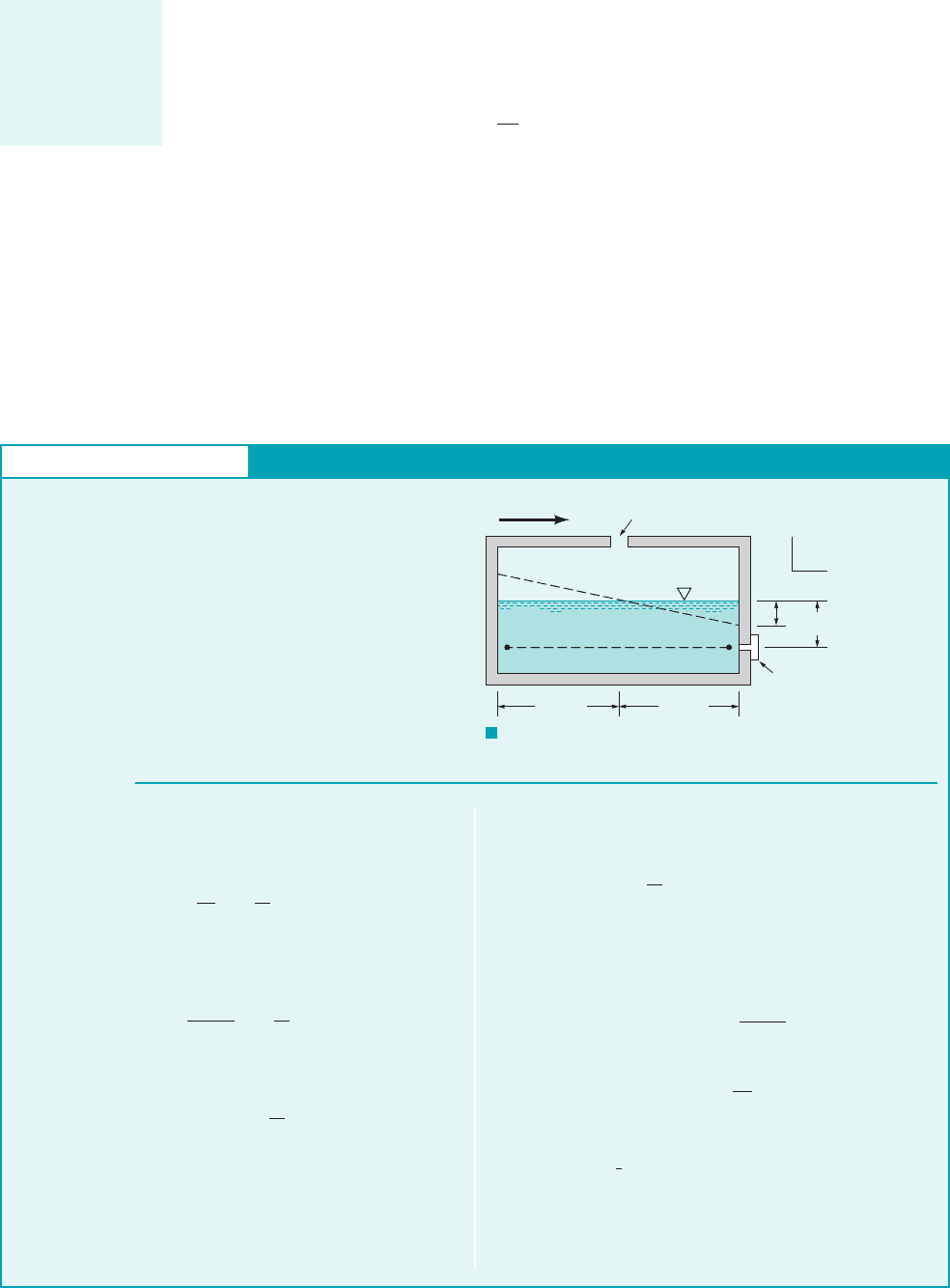
GIVEN The cross section for the fuel tank of an experimental
vehicle is shown in Fig. E2.11. The rectangular tank is vented to
the atmosphere and the specific gravity of the fuel is SG 0.65.
A pressure transducer is located in its side as illustrated. During
testing of the vehicle, the tank is subjected to a constant linear ac-
celeration,
FIND (a) Determine an expression that relates and the pres-
sure at the transducer. (b) What is the maximum acceler-
ation that can occur before the fuel level drops below the trans-
ducer?
1in lb
ft
2
2
a
y
a
y
.
S
OLUTION
(a) For a constant horizontal acceleration the fuel will move as
a rigid body, and from Eq. 2.28 the slope of the fuel surface can
be expressed as
since Thus, for some arbitrary the change in depth, of
liquid on the right side of the tank can be found from the equation
or
Since there is no acceleration in the vertical, z, direction, the
pressure along the wall varies hydrostatically as shown by Eq.
2.26. Thus, the pressure at the transducer is given by the rela-
tionship
p gh
z
1
10.75 ft2 a
a
y
g
b
z
1
0.75 ft
a
y
g
z
1
,a
y
,a
z
0.
dz
dy
a
y
g
where h is the depth of fuel above the transducer, and therefore
(Ans)
for As written, p would be given in
(b) The limiting value for 1when the fuel level reaches
the transducer2can be found from the equation
or
and for standard acceleration of gravity
(Ans)
COMMENT Note that the pressure in horizontal layers is not
constant in this example since Thus, for exam-
ple,
p
1
p
2
.
0p
0y ra
y
0.
1a
y
2
max
2
3
132.2 ft
s
2
2 21.5 ft
s
2
1a
y
2
max
2g
3
0.5 ft 10.75 ft2 c
1a
y
2
max
g
d
1a
y
2
max
lb
ft
2
.
z
1
0.5 ft.
20.3 30.4
a
y
g
p 10.652162.4 lb
ft
3
230.5 ft 10.75 ft21a
y
g24
F I G U R E E2.11
a
y
Vent
Air
Fuel
(1)(2)
0.75 ft 0.75 ft
Transducer
0.5 ft
z
1
y
z
JWCL068_ch02_038-092.qxd 8/19/08 10:16 PM Page 74
2.12 Pressure Variation in a Fluid with Rigid-Body Motion 75
2.12.2 Rigid-Body Rotation
After an initial “start-up” transient, a fluid contained in a tank that rotates with a constant angular
velocity about an axis as is shown in Fig. 2.30 will rotate with the tank as a rigid body. It is
known from elementary particle dynamics that the acceleration of a fluid particle located at a dis-
tance r from the axis of rotation is equal in magnitude to and the direction of the acceleration
is toward the axis of rotation, as is illustrated in the figure. Since the paths of the fluid particles
are circular, it is convenient to use cylindrical polar coordinates r, and z, defined in the insert in
Fig. 2.30. It will be shown in Chapter 6 that in terms of cylindrical coordinates the pressure gra-
dient can be expressed as
(2.29)
Thus, in terms of this coordinate system
and from Eq. 2.2
(2.30)
These results show that for this type of rigid-body rotation, the pressure is a function of two vari-
ables r and z, and therefore the differential pressure is
or
(2.31)
On a horizontal plane (dz 0), it follows from Eq. 2.31 that dp dr
2
r, which is greater than
zero. Hence, as illustrated in the figure in the margin, because of centrifugal acceleration, the pres-
sure increases in the radial direction.
Along a surface of constant pressure, such as the free surface, so that from Eq. 2.31
1using 2
Integration of this result gives the equation for surfaces of constant pressure as
(2.32)z
v
2
r
2
2g
constant
dz
dr
rv
2
g
g rg
dp 0,
dp rrv
2
dr g dz
dp
0p
0r
dr
0p
0z
dz
0p
0r
rrv
2
0p
0u
0
0p
0z
g
a
r
rv
2
ê
r
a
u
0
a
z
0
§p
0p
0r
ê
r
1
r
0p
0u
ê
u
0p
0z
ê
z
§p
u,
rv
2
,
v
A fluid contained in
a tank that is rotat-
ing with a constant
angular velocity
about an axis will
rotate as a rigid
body.
z = constant
p
r
dr
dp
dr
dp
–––
=
r
w
2
r
F I G U R E 2.30 Rigid-body rotation of a liquid in a tank. (Photograph courtesy of Geno Pawlak.)
θ
θ
r
x
y
z
e
r
e
z
e
a
r
= r
2
ω
ω
r
Axis of
rotation
(
b)(c)(a)
ω
JWCL068_ch02_038-092.qxd 8/19/08 10:16 PM Page 75
F I G U R E 2.31 Pressure
distribution in a rotating liquid.
76 Chapter 2 ■ Fluid Statics
This equation reveals that these surfaces of constant pressure are parabolic, as illustrated in Fig. 2.31.
Integration of Eq. 2.31 yields
or
(2.33)
where the constant of integration can be expressed in terms of a specified pressure at some arbi-
trary point This result shows that the pressure varies with the distance from the axis of ro-
tation, but at a fixed radius, the pressure varies hydrostatically in the vertical direction as shown
in Fig. 2.31.
r
0
, z
0
.
p
rv
2
r
2
2
gz constant
冮
dp rv
2
冮
r dr g
冮
dz
Constant
pressure
lines
p
1
p
2
p
3
p
4
p
1
p
2
p
3
p
4
2
r
2
____
2
g
ω
r
y
x
z
The free surface in
a rotating liquid is
curved rather than
flat.
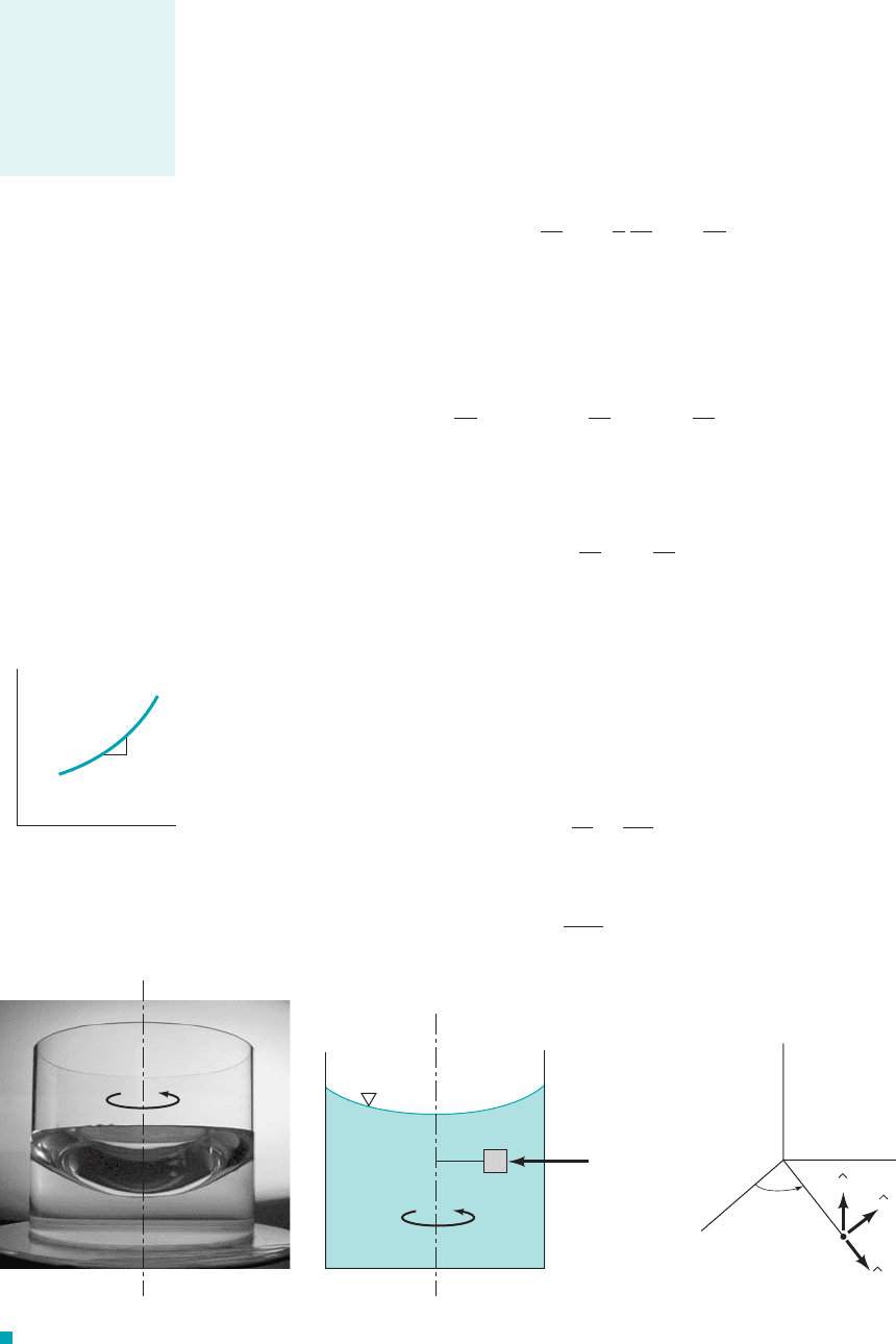
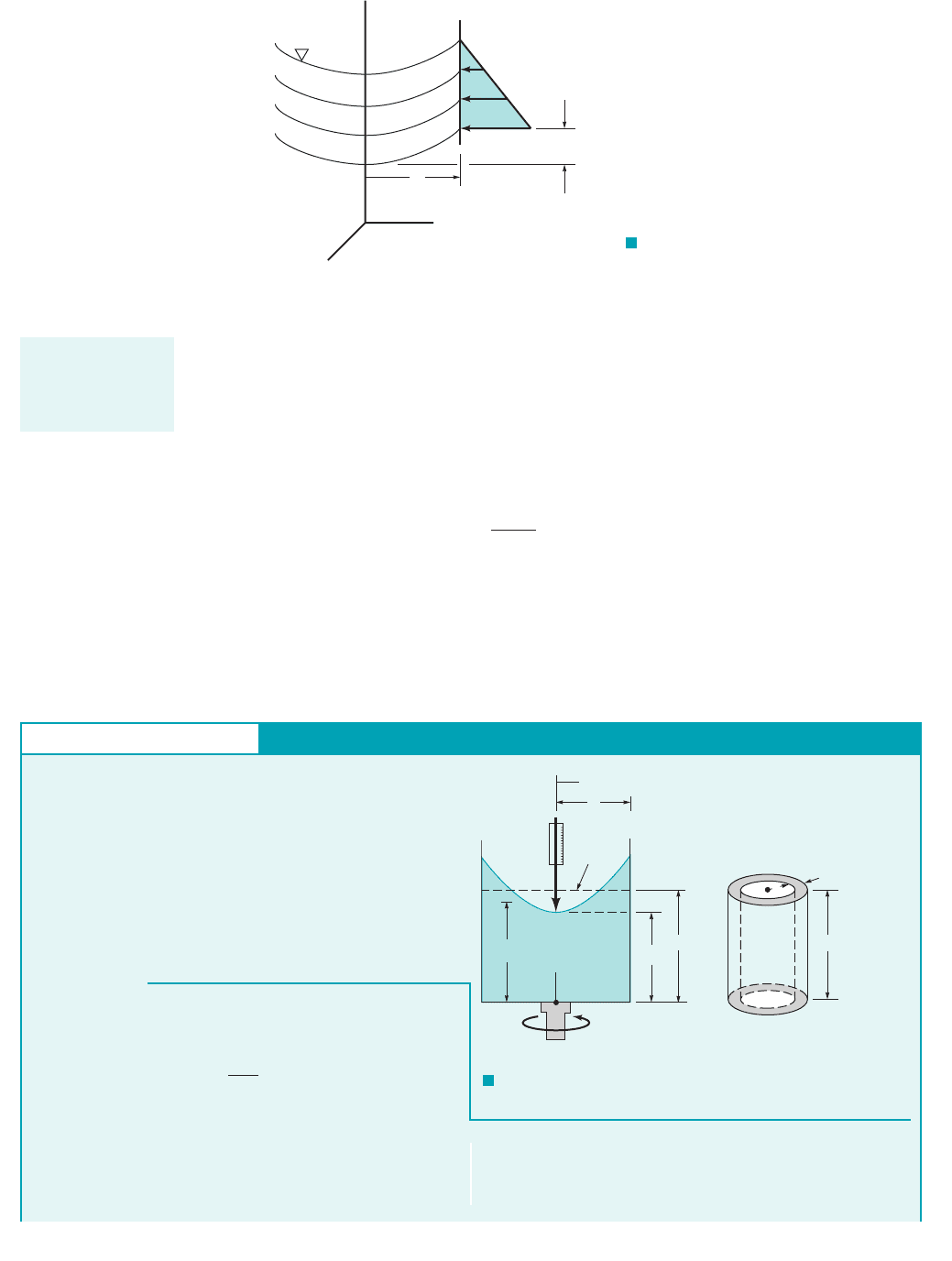
E
XAMPLE 2.12
GIVEN It has been suggested that the angular velocity, of a
rotating body or shaft can be measured by attaching an open
cylinder of liquid, as shown in Fig. E2.12a, and measuring with
some type of depth gage the change in the fluid level,
caused by the rotation of the fluid.
FIND Determine the relationship between this change in fluid
level and the angular velocity.
H h
0
,
v,
S
OLUTION
cylindrical shell is taken at some arbitrary radius, r, and its vol-
ume is
dV2prh dr
Free Surface Shape of Liquid in a Rotating Tank
F I G U R E E2.12
r
h
H
R
r
h
0
h
dr
(b)(a)
ω
0
z
Depth
gage
Initial
depth
The height, h, of the free surface above the tank bottom can be de-
termined from Eq. 2.32, and it follows that
The initial volume of fluid in the tank, is equal to
The volume of the fluid with the rotating tank can be found with
the aid of the differential element shown in Fig. E2.12b. This
V
i
pR
2
H
V
i
,
h
v
2
r
2
2g
h
0
JWCL068_ch02_038-092.qxd 8/19/08 10:16 PM Page 76