Munson B.R. Fundamentals of Fluid Mechanics
Подождите немного. Документ загружается.

When a surface is submerged in a fluid, forces develop on the surface due to the fluid. The deter-
mination of these forces is important in the design of storage tanks, ships, dams, and other hy-
draulic structures. For fluids at rest we know that the force must be perpendicular to the surface
since there are no shearing stresses present. We also know that the pressure will vary linearly with
depth as shown in Fig. 2.16 if the fluid is incompressible. For a horizontal surface, such as the bot-
tom of a liquid-filled tank 1Fig. 2.16a2, the magnitude of the resultant force is simply
where p is the uniform pressure on the bottom and A is the area of the bottom. For the open tank
shown, Note that if atmospheric pressure acts on both sides of the bottom, as is illustrated,
the resultant force on the bottom is simply due to the liquid in the tank. Since the pressure is con-
stant and uniformly distributed over the bottom, the resultant force acts through the centroid of the
area as shown in Fig. 2.16a. As shown in Fig. 2.16b, the pressure on the ends of the tank is not
uniformly distributed. Determination of the resultant force for situations such as this is presented
below.
p gh.
F
R
pA,
2.8 Hydrostatic Force on a Plane Surface 57
(a)
Diaphragm
Case
Electrical connections
Beam (strain gages deposited on beam)
Link pin
Diaphragm
Armature
Diaphragm
stop
(
b)
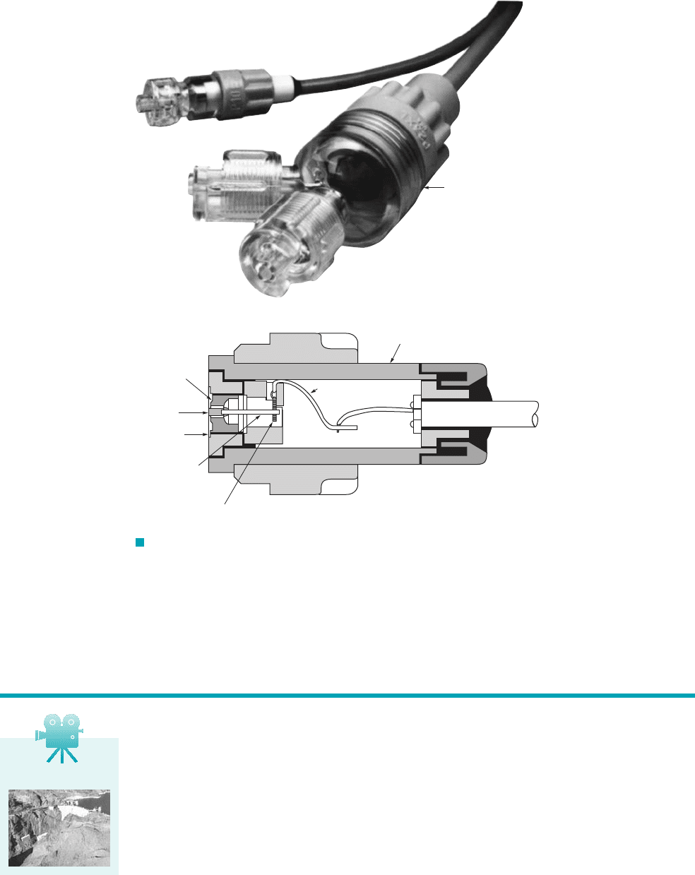
F I G U R E 2.15 (a) Two different sized strain-gage pressure transducers
(Spectramed Models P10EZ and P23XL) commonly used to measure physiological
pressures. Plastic domes are filled with fluid and connected to blood vessels through a
needle or catheter. (Photograph courtesy of Spectramed, Inc.) (b) Schematic diagram of
the P23XL transducer with the dome removed. Deflection of the diaphragm due to
pressure is measured with a silicon beam on which strain gages and an associated
bridge circuit have been deposited.
2.8 Hydrostatic Force on a Plane Surface
V2.4 Hoover dam
JWCL068_ch02_038-092.qxd 8/19/08 10:14 PM Page 57
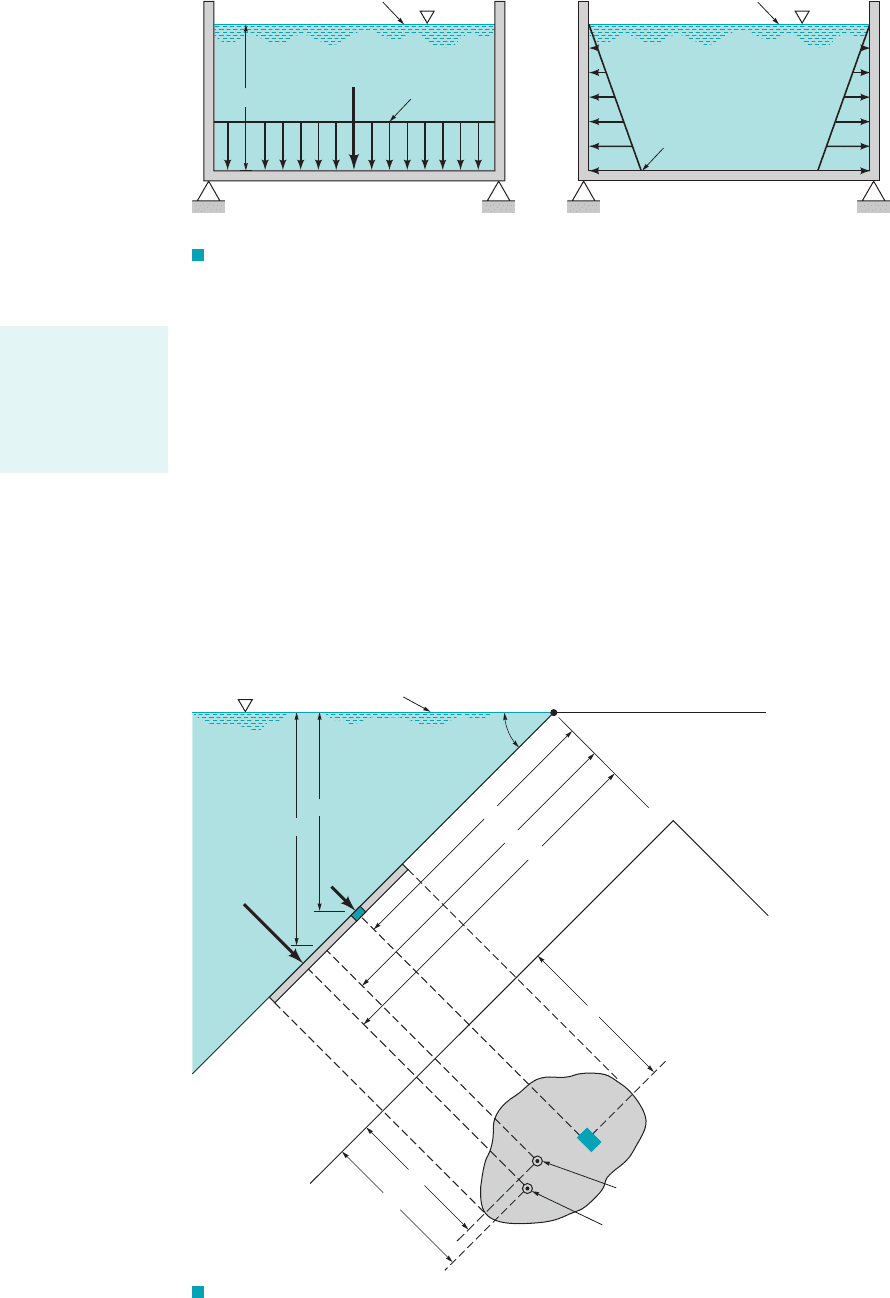
F I G U R E 2.16 (a) Pressure distribution and resultant hydrostatic force on the
bottom of an open tank. (b) Pressure distribution on the ends of an open tank.
58 Chapter 2 ■ Fluid Statics
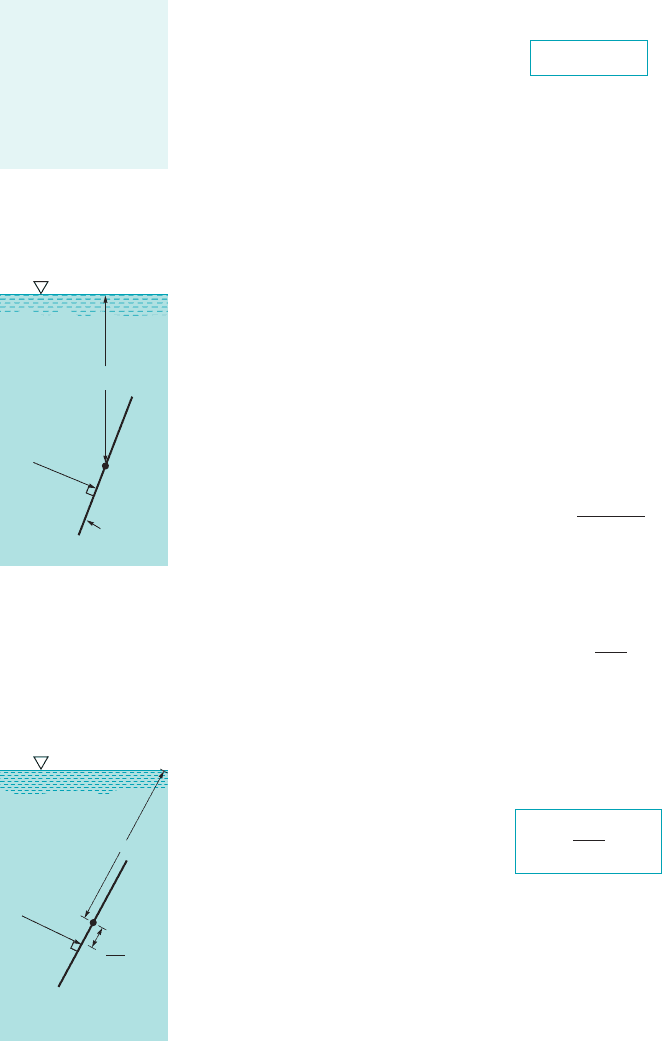
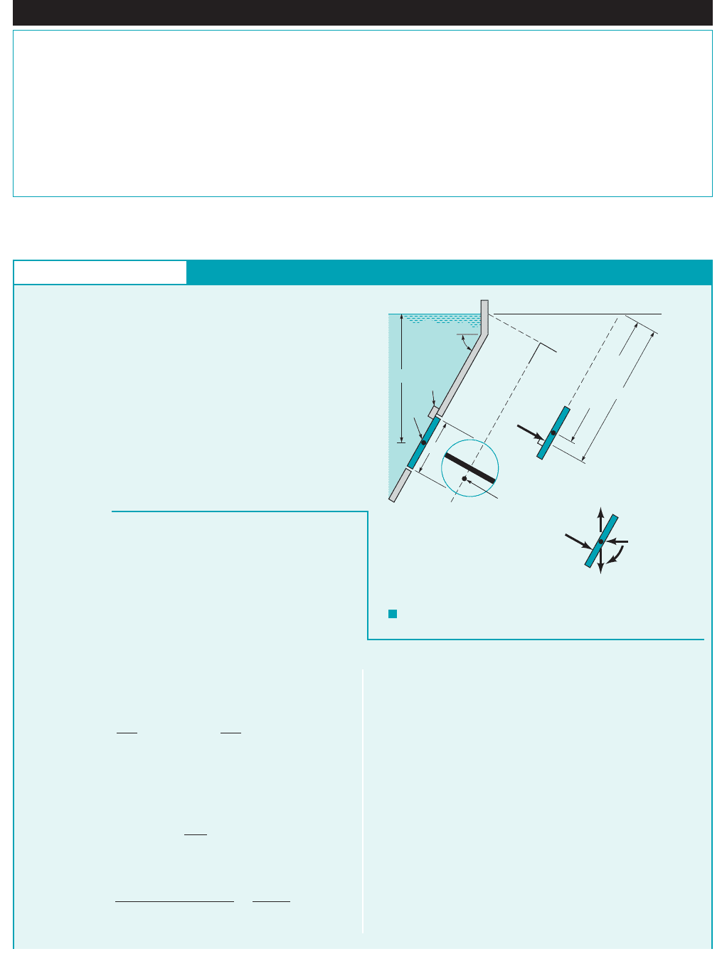
For the more general case in which a submerged plane surface is inclined, as is illustrated
in Fig. 2.17, the determination of the resultant force acting on the surface is more involved. For
the present we will assume that the fluid surface is open to the atmosphere. Let the plane in which
the surface lies intersect the free surface at 0 and make an angle with this surface as in Fig. 2.17.
The x–y coordinate system is defined so that 0 is the origin and y 0 (i.e., the x-axis) is directed
along the surface as shown. The area can have an arbitrary shape as shown. We wish to determine
the direction, location, and magnitude of the resultant force acting on one side of this area due to
the liquid in contact with the area. At any given depth, h, the force acting on dA 1the differential
area of Fig. 2.172is and is perpendicular to the surface. Thus, the magnitude of the
resultant force can be found by summing these differential forces over the entire surface. In equa-
tion form
F
R
冮
A
gh dA
冮
A
gy sin u dA
dF gh dA
u
Free surface
p = 0
Specific weight =
γ
F
R
h
p
= 0
p = h
γ
(a) Pressure on tank bottom
Free surface
p = 0
Specific weight =
γ
p = 0
p = h
γ
(b) Pressure on tank ends
y
y
c
y
R
x
R
x
c
c
CP
Centroid,
c
Location of
resultant force
(center of pressure, CP)
dA
A
x
x
y
θ
0
Free surface
h
h
c
F
R
dF
F I G U R E 2.17 Notation for hydrostatic force on an inclined plane
surface of arbitrary shape.
The resultant force
of a static fluid on a
plane surface is due
to the hydrostatic
pressure distribution
on the surface.
JWCL068_ch02_038-092.qxd 8/19/08 10:14 PM Page 58
where For constant and
(2.17)
The integral appearing in Eq. 2.17 is the first moment of the area with respect to the x axis, so we
can write
where is the y coordinate of the centroid of area A measured from the x axis which passes through 0.
Equation 2.17 can thus be written as
or more simply as
(2.18)
where is the vertical distance from the fluid surface to the centroid of the area. Note that the
magnitude of the force is independent of the angle . As indicated by the figure in the margin, it
depends only on the specific weight of the fluid, the total area, and the depth of the centroid of
the area below the surface. In effect, Eq. 2.18 indicates that the magnitude of the resultant force
is equal to the pressure at the centroid of the area multiplied by the total area. Since all the differ-
ential forces that were summed to obtain are perpendicular to the surface, the resultant must
also be perpendicular to the surface.
Although our intuition might suggest that the resultant force should pass through the cen-
troid of the area, this is not actually the case. The y coordinate, of the resultant force can be
determined by summation of moments around the x axis. That is, the moment of the resultant force
must equal the moment of the distributed pressure force, or
and, therefore, since
The integral in the numerator is the second moment of the area (moment of inertia), with re-
spect to an axis formed by the intersection of the plane containing the surface and the free surface
1x axis2. Thus, we can write
Use can now be made of the parallel axis theorem to express as
where is the second moment of the area with respect to an axis passing through its centroid and
parallel to the x axis. Thus,
(2.19)
As shown by Eq. 2.19 and the figure in the margin, the resultant force does not pass through the
centroid but for nonhorizontal surfaces is always below it, since
The x coordinate, for the resultant force can be determined in a similar manner by sum-
ming moments about the y axis. Thus,
F
R
x
R
冮
A
g sin u xy dA
x
R
,
I
xc
y
c
A 7 0.
y
R
I
xc
y
c
A
y
c
I
xc
I
x
I
xc
Ay
2
c
I
x
y
R
I
x
y
c
A
I
x
,
y
R
冮
A
y
2
dA
y
c
A
F
R
gAy
c
sin u
F
R
y
R
冮
A
y dF
冮
A
g sin u y
2
dA
y
R
,
F
R
F
R
u
h
c
F
R
gh
c
A
F
R
gAy
c
sin u
y
c
冮
A
y dA y
c
A
F
R
g sin u
冮
A
y dA
ugh y sin u.
2.8 Hydrostatic Force on a Plane Surface 59
The magnitude of
the resultant fluid
force is equal to the
pressure acting at
the centroid of the
area multiplied by
the total area.
γ
A
h
c
c
F
R
= γh
c
A
c
y
c
I
xc
y
c
A
F
R
JWCL068_ch02_038-092.qxd 8/19/08 10:14 PM Page 59
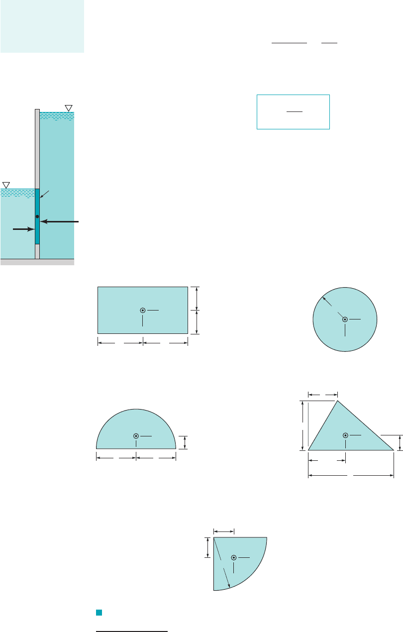
F I G U R E 2.18 Geometric properties of some common shapes.
and, therefore,
where is the product of inertia with respect to the x and y axes. Again, using the parallel axis
theorem,
1
we can write
(2.20)
where is the product of inertia with respect to an orthogonal coordinate system passing through
the centroid of the area and formed by a translation of the x–y coordinate system. If the submerged
area is symmetrical with respect to an axis passing through the centroid and parallel to either the
x or y axes, the resultant force must lie along the line since is identically zero in this
case. The point through which the resultant force acts is called the center of pressure. It is to be
noted from Eqs. 2.19 and 2.20 that as increases the center of pressure moves closer to the cen-
troid of the area. Since the distance will increase if the depth of submergence,
increases, or, for a given depth, the area is rotated so that the angle, decreases. Thus, the hydro-
static force on the right-hand side of the gate shown in the margin figure acts closer to the cen-
troid of the gate than the force on the left-hand side. Centroidal coordinates and moments of iner-
tia for some common areas are given in Fig. 2.18.
u,
h
c
,y
c
y
c
h
c
sin u,
y
c
I
xyc
x x
c
,
I
xyc
x
R
I
xyc
y
c
A
x
c
I
xy
x
R
冮
A
xy dA
y
c
A
I
xy
y
c
A
60 Chapter 2 ■ Fluid Statics
c
y
x
4R
–––
3
π
4R
–––
3
π
A =
R
2
–––––
4
π
I
xc
= I
yc
= 0.05488R
4
I
xyc
= –0.01647R
4
A =
R
2
–––––
2
π
I
xc
= 0.1098R
4
I
yc
= 0.3927R
4
I
xyc
= 0
A =
ab
–––
2
I
xc
=
I
xyc
= (b – 2d)
ba
3
–––-
–
36
ba
2
–––––
72
A = R
2
R
4
–––––
4
π
I
xc
= I
yc
=
I
xyc
= 0
π
A = ba
1
–––
12
I
xc
= ba
3
I
yc
= ab
3
I
xyc
= 0
1
–––
12
c
y
x
RR
4R
–––
3
π
c
y
x
b
+ d
–––––––
3
b
a
––
3
d
a
R
c
y
x
R
c
y
x
b
––
2
b
––
2
a
––
2
a
––
2
(
a) Rectangle (b) Circle
(c) Semicircle (d) Triangle
(
e) Quarter circle
1
Recall that the parallel axis theorem for the product of inertia of an area states that the product of inertia with respect to an orthogonal
set of axes 1x–y coordinate system2is equal to the product of inertia with respect to an orthogonal set of axes parallel to the original set
and passing through the centroid of the area, plus the product of the area and the x and y coordinates of the centroid of the area. Thus,
I
xy
I
xyc
Ax
c
y
c
.
The resultant fluid
force does not pass
through the cen-
troid of the area.
F
R
left
F
R
right
c
Gate
JWCL068_ch02_038-092.qxd 8/19/08 10:14 PM Page 60
2.8 Hydrostatic Force on a Plane Surface 61
Fluids in the News
The Three Gorges Dam The Three Gorges Dam being con-
structed on China’s Yangtze River will contain the world’s
largest hydroelectric power plant when in full operation. The
dam is of the concrete gravity type, having a length of 2309 me-
ters with a height of 185 meters. The main elements of the pro-
ject include the dam, two power plants, and navigation facilities
consisting of a ship lock and lift. The power plants will contain
26 Francis type turbines, each with a capacity of 700 megawatts.
The spillway section, which is the center section of the dam, is
483 meters long with 23 bottom outlets and 22 surface sluice
gates. The maximum discharge capacity is 102,500 cubic meters
per second. After more than 10 years of construction, the dam
gates were finally closed, and on June 10, 2003, the reservoir
had been filled to its interim level of 135 meters. Due to the
large depth of water at the dam and the huge extent of the stor-
age pool, hydrostatic pressure forces have been a major factor
considered by engineers. When filled to its normal pool level of
175 meters, the total reservoir storage capacity is 39.3 billion
cubic meters. The project is scheduled for completion in 2009.
(See Problem 2.79.)
Hydrostatic Force on a Plane Circular Surface
E
XAMPLE 2.6
GIVEN The 4-m-diameter circular gate of Fig. E2.6a is lo-
cated in the inclined wall of a large reservoir containing water
The gate is mounted on a shaft along its hor-
izontal diameter, and the water depth is 10 m above the shaft.
FIND Determine
(a) the magnitude and location of the resultant force exerted
on the gate by the water and
(b) the moment that would have to be applied to the shaft to
open the gate.
1g 9.80 kN
m
3
2.
S
OLUTION
F I G U R E E2.6
a
–
c
x
y
c
A
A
Center of
pressure
F
R
ᐃ
M
O
y
O
x
c
(a)
(
c)
(
b)
4 m
Shaft
Stop
10 m
60°
00
F
R
c
y
R
y
c
=
10 m
–––––––––
sin 60°
(a) To find the magnitude of the force of the water we can apply
Eq. 2.18,
and since the vertical distance from the fluid surface to the cen-
troid of the area is 10 m, it follows that
(Ans)
To locate the point 1center of pressure2through which acts,
we use Eqs. 2.19 and 2.20,
For the coordinate system shown, since the area is sym-
metrical, and the center of pressure must lie along the diameter A-
A. To obtain we have from Fig. 2.18
and is shown in Fig. E2.6b. Thus,
0.0866 m 11.55 m 11.6 m
y
R
1p
4212 m2
4
110 m
sin 60°214p m
2
2
10 m
sin 60°
y
c
I
xc
pR
4
4
y
R
,
x
R
0
x
R
I
xyc
y
c
A
x
c
y
R
I
xc
y
c
A
y
c
F
R
1230 10
3
N 1.23 MN
F
R
19.80 10
3
N
m
3
2110 m214p m
2
2
F
R
gh
c
A
and the distance 1along the gate2below the shaft to the center of
pressure is
(Ans)
We can conclude from this analysis that the force on the gate due
to the water has a magnitude of 1.23 MN and acts through a point
along its diameter A-A at a distance of 0.0866 m 1along the gate2
below the shaft. The force is perpendicular to the gate surface as
shown in Fig. E2.6b.
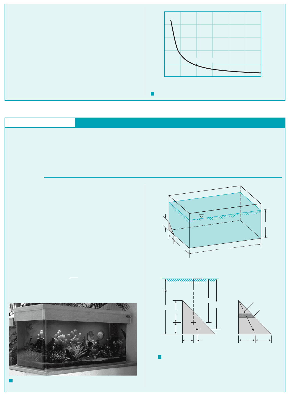
COMMENT By repeating the calculations for various values
of the depth to the centroid, h
c
, the results shown in Fig. E2.6d are
obtained. Note that as the depth increases, the distance between
the center of pressure and the centroid decreases.
(b) The moment required to open the gate can be obtained with
the aid of the free-body diagram of Fig. E2.6c. In this diagram w
y
R
y
c
0.0866 m
JWCL068_ch02_038-092.qxd 8/19/08 10:14 PM Page 61
62 Chapter 2 ■ Fluid Statics
is the weight of the gate and and are the horizontal and
vertical reactions of the shaft on the gate. We can now sum mo-
ments about the shaft
and, therefore,
(Ans)
1.07 10
5
N
#
m
11230 10
3
N210.0866 m2
M F
R
1y
R
y
c
2
a
M
c
0
O
y
O
x
0.5
0.4
0.3
0.2
0.1
0
0 5 10 15
h
c
, m
y
R
– y
c
, m
20 25 30
(10m, 0.0886 m)
F I G U R E E2.6
d
Hydrostatic Pressure Force on a Plane Triangular Surface
E
XAMPLE 2.7
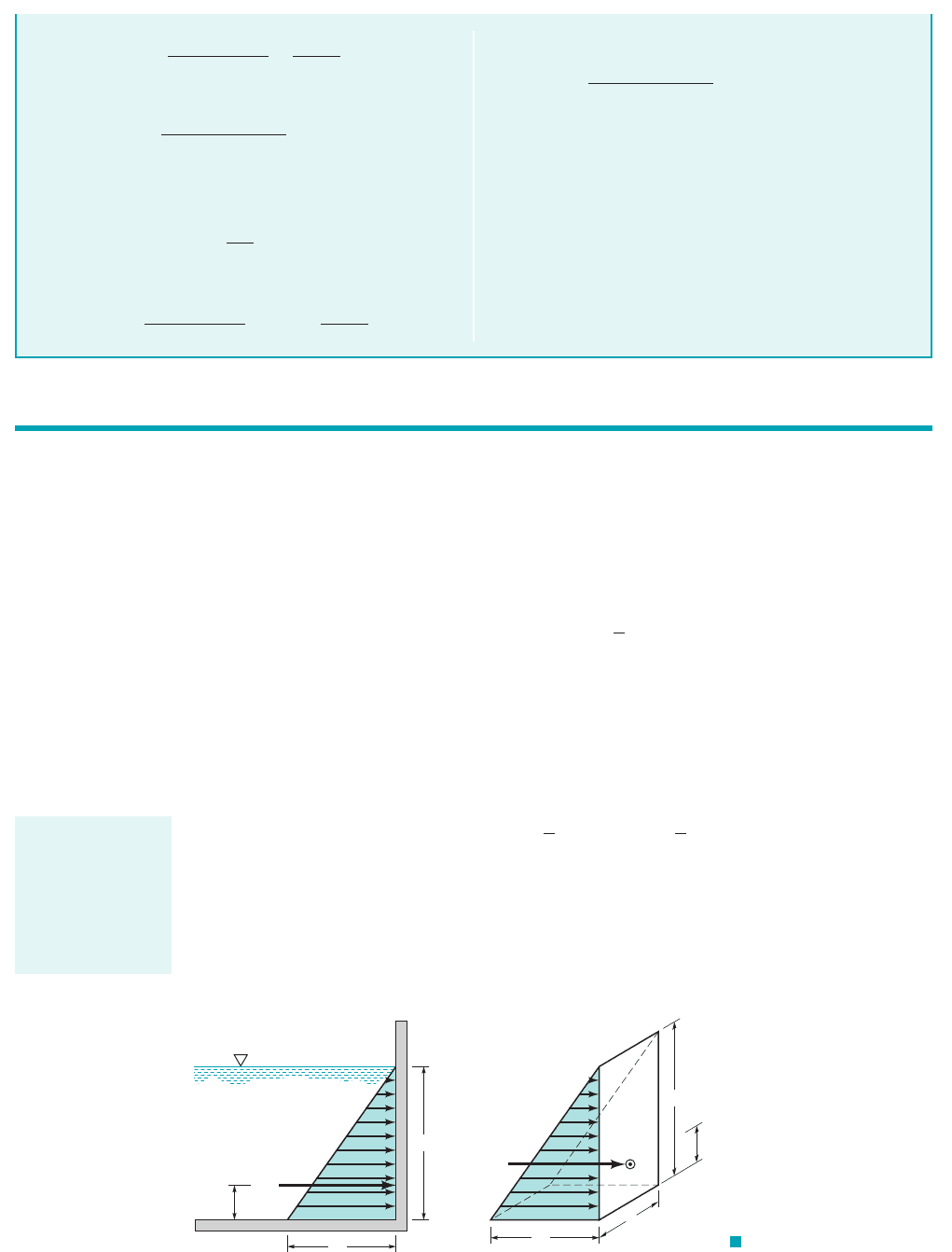
GIVEN An aquarium contains seawater to a
depth of 1 ft as shown in Fig. E2.7a. To repair some damage to
one corner of the tank, a triangular section is replaced with a new
section as illustrated in Fig. E2.7b.
1g 64.0 lb
ft
3
2
(a) The various distances needed to solve this problem are
shown in Fig. E2.7c. Since the surface of interest lies in a ver-
tical plane, and from Eq. 2.18 the magnitude
of the force is
(Ans)
COMMENT Note that this force is independent of the tank
length. The result is the same if the tank is 0.25 ft, 25 ft, or 25 miles
long.
(b) The y coordinate of the center of pressure 1CP2is found from
Eq. 2.19,
and from Fig. 2.18
y
R
I
xc
y
c
A
y
c
164.0 lb
ft
3
210.9 ft2310.3 ft2
2
24 2.59 lb
F
R
gh
c
A
y
c
h
c
0.9 ft,
S
OLUTION
FIND Determine
(a) the magnitude of the force of the seawater on this triangular
area, and
(b) the location of this force.
F I G U R E E2.7
b–d
0.3 ft
0.3 ft
0.9 ft
2.5 ft
1 ft
(
b)
(
c)(d)
1 ft
0.1 ft
0.2 ft
0.1 ft
0.15 ft 0.15 ft
Median line
δ
A
y
R
x
R
y
c
y
x
c
CP
c
CP
F I G U R E E2.7
a
(Photograph courtesy
of Tenecor Tanks, Inc.)
JWCL068_ch02_038-092.qxd 9/23/08 9:09 AM Page 62
2.9 Pressure Prism 63
2.9 Pressure Prism
An informative and useful graphical interpretation can be made for the force developed by a fluid
acting on a plane rectangular area. Consider the pressure distribution along a vertical wall of a tank
of constant width b, which contains a liquid having a specific weight Since the pressure must
vary linearly with depth, we can represent the variation as is shown in Fig. 2.19a, where the pres-
sure is equal to zero at the upper surface and equal to at the bottom. It is apparent from this
diagram that the average pressure occurs at the depth and therefore the resultant force acting
on the rectangular area is
which is the same result as obtained from Eq. 2.18. The pressure distribution shown in Fig. 2.19a
applies across the vertical surface so we can draw the three-dimensional representation of the pres-
sure distribution as shown in Fig. 2.19b. The base of this “volume” in pressure-area space is the
plane surface of interest, and its altitude at each point is the pressure. This volume is called the pres-
sure prism, and it is clear that the magnitude of the resultant force acting on the rectangular surface
is equal to the volume of the pressure prism. Thus, for the prism of Fig. 2.19b the fluid force is
where bh is the area of the rectangular surface, A.
The resultant force must pass through the centroid of the pressure prism. For the volume un-
der consideration the centroid is located along the vertical axis of symmetry of the surface, and at
a distance of above the base 1since the centroid of a triangle is located at above its base2.
This result can readily be shown to be consistent with that obtained from Eqs. 2.19 and 2.20.
h
3h
3
F
R
volume
1
2
1gh21bh2 g a
h
2
b A
F
R
p
av
A g a
h
2
b A
A bh
h
2,
gh
g.
F
R
γ
h
h
h
–
3
(
a)(b)
γ
h
h
F
R
h
–
3
b
CP
p
F I G U R E 2.19
Pressure prism for vertical
rectangular area.
The magnitude of
the resultant fluid
force is equal to the
volume of the pres-
sure prism and
passes through its
centroid.
so that
(Ans)
Similarly, from Eq. 2.20
and from Fig. 2.18
I
xyc
10.3 ft210.3 ft2
2
72
10.3 ft2
0.0081
72
ft
4
x
R
I
xyc
y
c
A
x
c
0.00556 ft 0.9 ft 0.906 ft
y
R
0.0081
36 ft
4
10.9 ft210.09
2 ft
2
2
0.9 ft
I
xc
10.3 ft210.3 ft2
3
36
0.0081
36
ft
4
so that
(Ans)
COMMENT Thus, we conclude that the center of pressure is
0.00278 ft to the right of and 0.00556 ft below the centroid of the
area. If this point is plotted, we find that it lies on the median line
for the area as illustrated in Fig. E2.7d. Since we can think of the
total area as consisting of a number of small rectangular strips of
area 1and the fluid force on each of these small areas acts
through its center2, it follows that the resultant of all these parallel
forces must lie along the median.
dA
x
R
0.0081
72 ft
4
10.9 ft210.09
2 ft
2
2
0 0.00278 ft
JWCL068_ch02_038-092.qxd 8/19/08 10:15 PM Page 63
64 Chapter 2 ■ Fluid Statics
This same graphical approach can be used for plane rectangular surfaces that do not extend
up to the fluid surface, as illustrated in Fig. 2.20a. In this instance, the cross section of the pres-
sure prism is trapezoidal. However, the resultant force is still equal in magnitude to the volume of
the pressure prism, and it passes through the centroid of the volume. Specific values can be ob-
tained by decomposing the pressure prism into two parts, ABDE and BCD, as shown in Fig. 2.20b.
Thus,
where the components can readily be determined by inspection for rectangular surfaces. The loca-
tion of can be determined by summing moments about some convenient axis, such as one pass-
ing through A. In this instance
and can be determined by inspection.
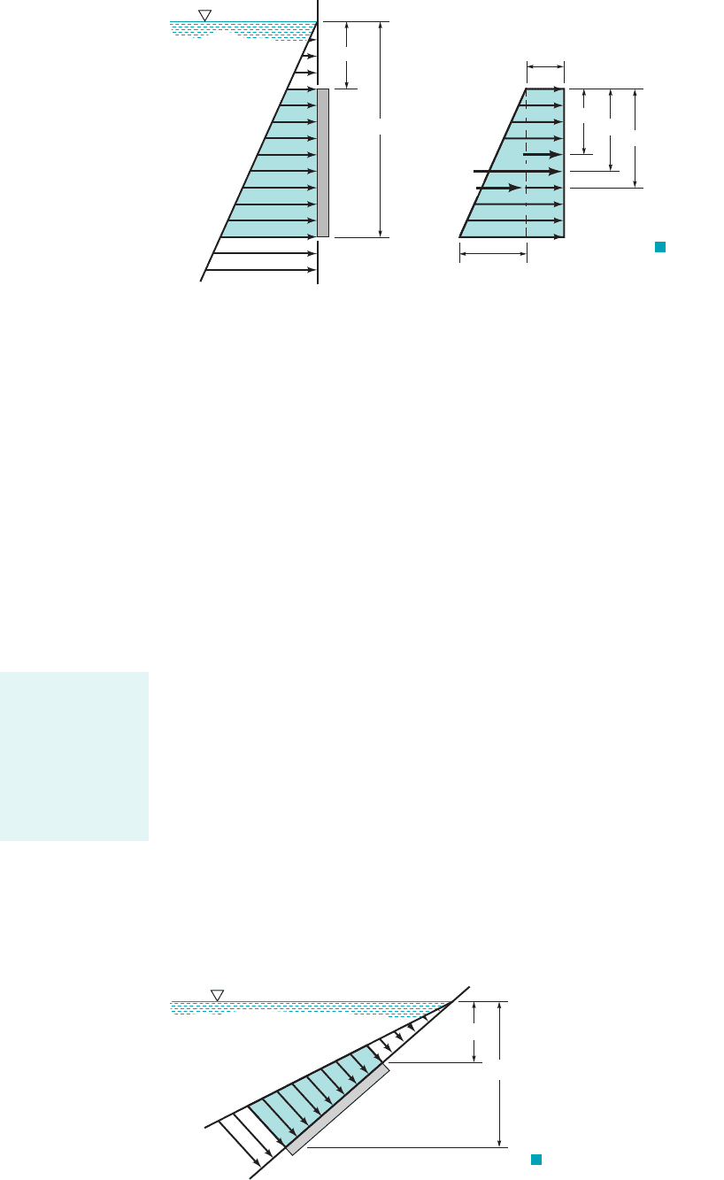
For inclined plane rectangular surfaces the pressure prism can still be developed, and the
cross section of the prism will generally be trapezoidal, as is shown in Fig. 2.21. Although it is usu-
ally convenient to measure distances along the inclined surface, the pressures developed depend
on the vertical distances as illustrated.
The use of pressure prisms for determining the force on submerged plane areas is convenient
if the area is rectangular so the volume and centroid can be easily determined. However, for other
nonrectangular shapes, integration would generally be needed to determine the volume and centroid.
In these circumstances it is more convenient to use the equations developed in the previous section,
in which the necessary integrations have been made and the results presented in a convenient and
compact form that is applicable to submerged plane areas of any shape.
The effect of atmospheric pressure on a submerged area has not yet been considered, and we
may ask how this pressure will influence the resultant force. If we again consider the pressure dis-
tribution on a plane vertical wall, as is shown in Fig. 2.22a, the pressure varies from zero at the
surface to at the bottom. Since we are setting the surface pressure equal to zero, we are usinggh
y
1
and y
2
F
R
y
A
F
1
y
1
F
2
y
2
F
R
F
R
F
1
F
2
h
1
h
2
p
(a)(b)
CDE
AB
F
R
F
2
F
1
y
1
y
A
y
2
(h
2
- h
1
)
γ
h
1
γ
F I G U R E 2.20
Graphical representation of
hydrostatic forces on a
vertical rectangular surface.
γ
h
2
h
2
γ
h
1
h
1
F I G U R E 2.21 Pressure variation
along an inclined plane area.
The use of the pres-
sure prism concept
to determine the
force on a sub-
merged area is best
suited for plane
rectangular
surfaces.
JWCL068_ch02_038-092.qxd 8/19/08 10:15 PM Page 64
atmospheric pressure as our datum, and thus the pressure used in the determination of the fluid
force is gage pressure. If we wish to include atmospheric pressure, the pressure distribution will
be as is shown in Fig. 2.22b. We note that in this case the force on one side of the wall now con-
sists of as a result of the hydrostatic pressure distribution, plus the contribution of the atmos-
pheric pressure, where A is the area of the surface. However, if we are going to include the
effect of atmospheric pressure on one side of the wall, we must realize that this same pressure acts
on the outside surface 1assuming it is exposed to the atmosphere2, so that an equal and opposite force
will be developed as illustrated in the figure. Thus, we conclude that the resultant fluid force on the
surface is that due only to the gage pressure contribution of the liquid in contact with the surface—
the atmospheric pressure does not contribute to this resultant. Of course, if the surface pressure of
the liquid is different from atmospheric pressure 1such as might occur in a closed tank2, the resul-
tant force acting on a submerged area, A, will be changed in magnitude from that caused simply
by hydrostatic pressure by an amount where is the gage pressure at the liquid surface 1the
outside surface is assumed to be exposed to atmospheric pressure2.
p
s
p
s
A,
p
atm
A,
F
R
2.9 Pressure Prism 65
F
R
F
R
p
atm
p
atm
p
atm
p
atm
AA
(a)(b)
h
h
γ
p
atm
p
F I G U R E 2.22 Effect of atmospheric pressure on the resultant
force acting on a plane vertical wall.
The resultant fluid
force acting on a
submerged area is
affected by the
pressure at the free
surface.
Use of the Pressure Prism Concept
E
XAMPLE 2.8
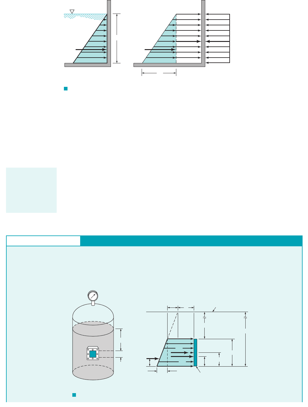
GIVEN A pressurized tank contains oil and has a
square, 0.6-m by 0.6-m plate bolted to its side, as is illustrated in
Fig. E2.8a. The pressure gage on the top of the tank reads 50 kPa,
and the outside of the tank is at atmospheric pressure.
1SG 0.902
FIND What is the magnitude and location of the resultant force
on the attached plate?
p = 50 kPa
Air
2 m
0.6 m
(
a)
F
1
F
R
Plate
O
(h
2
– h
1
)
γ
0.2 m
F
2
y
O
0.3 m
0.6 m
h
2
= 2.6 m
h
1
= 2 m
h
1
γ
p
s
Oil surface
(b)
Oil
F I G U R E E2.8
JWCL068_ch02_038-092.qxd 8/19/08 10:15 PM Page 65
66 Chapter 2 ■ Fluid Statics
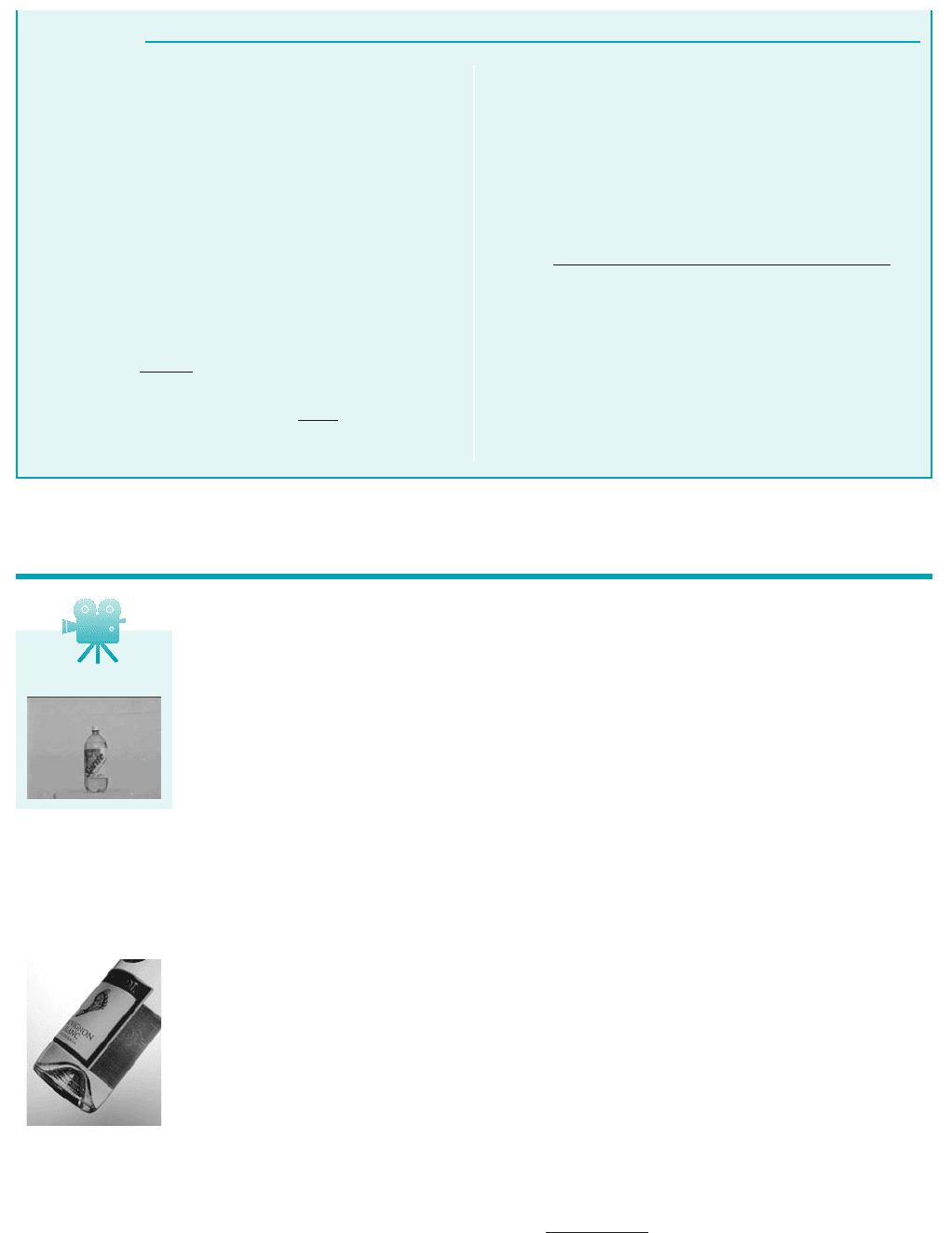
The equations developed in Section 2.8 for the magnitude and location of the resultant force act-
ing on a submerged surface only apply to plane surfaces. However, many surfaces of interest
1such as those associated with dams, pipes, and tanks2are nonplanar. The domed bottom of the
beverage bottle shown in the figure in the margin shows a typical curved surface example. Al-
though the resultant fluid force can be determined by integration, as was done for the plane sur-
faces, this is generally a rather tedious process and no simple, general formulas can be devel-
oped. As an alternative approach we will consider the equilibrium of the fluid volume enclosed
by the curved surface of interest and the horizontal and vertical projections of this surface.
For example, consider a curved portion of the swimming pool shown in Fig. 2.23a. We wish
to find the resultant fluid force acting on section BC (which has a unit length perpendicular to the
plane of the paper) shown in Fig. 2.23b. We first isolate a volume of fluid that is bounded by the
surface of interest, in this instance section BC, the horizontal plane surface AB, and the vertical
plane surface AC. The free-body diagram for this volume is shown in Fig. 2.23c. The magnitude
and location of forces can be determined from the relationships for planar surfaces. The
weight, is simply the specific weight of the fluid times the enclosed volume and acts through
the center of gravity 1CG2of the mass of fluid contained within the volume. The forces
represent the components of the force that the tank exerts on the fluid.
In order for this force system to be in equilibrium, the horizontal component must be
equal in magnitude and collinear with and the vertical component equal in magnitude and
collinear with the resultant of the vertical forces This follows since the three forces act-
ing on the fluid mass 1 the resultant of and the resultant force that the tank exerts on
the mass2must form a concurrent force system. That is, from the principles of statics, it is known
that when a body is held in equilibrium by three nonparallel forces, they must be concurrent 1their
lines of action intersect at a common point2, and coplanar. Thus,
and the magnitude of the resultant is obtained from the equation
F
R
21F
H
2
2
1F
V
2
2
F
V
F
1
w
F
H
F
2
F
1
and w,F
2
,
F
1
and w.
F
V
F
2
,
F
H
F
H
and F
V
w,
F
1
and F
2
2.10 Hydrostatic Force on a Curved Surface
S
OLUTION
The pressure distribution acting on the inside surface of the plate is
shown in Fig. E2.8b. The pressure at a given point on the plate is
due to the air pressure, at the oil surface, and the pressure due to
the oil, which varies linearly with depth as is shown in the figure.
The resultant force on the plate 1having an area A2is due to the com-
ponents, where F
1
and F
2
are due to the rectangular and
triangular portions of the pressure distribution, respectively. Thus,
and
0.954 10
3
N
10.902
19.81 10
3
N
m
3
2 a
0.6 m
2
b
10.36 m
2
2
F
2
g a
h
2
h
1
2
b A
24.4 10
3
N
10.90219.81 10
3
N
m
3
212 m2410.36 m
2
2
350 10
3
N
m
2
F
1
1
p
s
gh
1
2
A
F
1
and F
2
,
p
s
,
The magnitude of the resultant force, is therefore
(Ans)
The vertical location of can be obtained by summing mo-
ments around an axis through point O so that
or
(Ans)
Thus, the force acts at a distance of 0.296 m above the bottom of
the plate along the vertical axis of symmetry.
COMMENT Note that the air pressure used in the calculation
of the force was gage pressure. Atmospheric pressure does not af-
fect the resultant force 1magnitude or location2, since it acts on
both sides of the plate, thereby canceling its effect.
0.296 m
y
O
124.4 10
3
N210.3 m2 10.954 10
3
N210.2 m2
25.4 10
3
N
F
R
y
O
F
1
10.3 m2 F
2
10.2 m2
F
R
F
R
F
1
F
2
25.4 10
3
N 25.4 kN
F
R
,
V2.5 Pop bottle
JWCL068_ch02_038-092.qxd 8/19/08 10:15 PM Page 66