Moran M.J., Shapiro H.N. Fundamentals of Engineering Thermodynamics
Подождите немного. Документ загружается.


Areas on the T–s and p–y diagrams of Fig. 9.10 can be interpreted as heat and
work, respectively, per unit of mass flowing. On the T–s diagram, area 2–3–a–b–2
represents the heat added per unit of mass and area 1–4–a–b–1 is the heat rejected
per unit of mass. On the p–y diagram, area 1–2–a–b–1 represents the compressor work
input per unit of mass and area 3–4–b–a–3 is the turbine work output per unit of
mass. The enclosed area on each figure can be interpreted as the net work output or,
equivalently, the net heat added.
When air table data are used to conduct an analysis involving the ideal Brayton
cycle, the following relationships, based on Eq. 6.41, apply for the isentropic processes
1–2 and 3–4
p
r2
5 p
r1
p
2
p
1
(9.21)
p
r4
5 p
r3
p
4
p
3
5 p
r3
p
1
p
2
(9.22)
where p
2
/p
1
is the compressor pressure ratio. Recall that p
r
is tabulated versus tem-
perature in Tables A-22. Since air flows through the heat exchangers of the ideal cycle
at constant pressure, it follows that p
4
/p
3
5 p
1
/p
2
. This relationship has been used in
writing Eq. 9.22.
When an ideal Brayton cycle is analyzed on a cold air-standard basis, the specific
heats are taken as constant. Equations 9.21 and 9.22 are then replaced, respectively,
by the following expressions, based on Eq. 6.43
T
2
5 T
1
a
p
2
p
1
b
1k212
/
k
(9.23)
T
4
5 T
3
a
p
4
p
3
b
1k212
/
k
5 T
3
a
p
1
p
2
b
1k212
/
k
(9.24)
where k is the specific heat ratio, k 5 c
p
/c
y
.
In the next example, we illustrate the analysis of an ideal air-standard Brayton
cycle and compare results with those obtained on a cold air-standard basis.
TAKE NOTE...
For internally reversible
flows through control
volumes at steady state,
see Sec. 6.13 for area
interpretations of work and
heat transfer on p–y and
T–s diagrams, respectively.
c c c c EXAMPLE 9.4 c
Air enters the compressor of an ideal air-standard Brayton cycle at 100 kPa, 300 K, with a volumetric flow rate
of 5 m
3
/s. The compressor pressure ratio is 10. The turbine inlet temperature is 1400 K. Determine (a) the thermal
efficiency of the cycle, (b) the back work ratio, (c) the net power developed, in kW.
SOLUTION
Known:
An ideal air-standard Brayton cycle operates with given compressor inlet conditions, given turbine inlet
temperature, and a known compressor pressure ratio.
Analyzing the Ideal Brayton Cycle
9.6 Air-Standard Brayton Cycle 513
Fig. 9.10
Air-standard ideal Brayton cycle.
T
s
2
1
2′
3′
3
4
b a
p
v
41
23
p = c
p = c
s = c
s = c
a
b
A
A
Brayton_Cycle
A.29 – Tab a
c09GasPowerSystems.indd Page 513 7/19/10 9:58:10 AM users-133c09GasPowerSystems.indd Page 513 7/19/10 9:58:10 AM users-133 /Users/users-133/Desktop/Ramakant_04.05.09/WB00113_R1:JWCL170/New/Users/users-133/Desktop/Ramakant_04.05.09/WB00113_R1:JWCL170/New

514 Chapter 9 Gas Power Systems
Find: Determine the thermal efficiency, the back work ratio, and the net power developed, in kW.
Schematic and Given Data:
Engineering Model:
1.
Each component is analyzed as a control volume at steady state. The control volumes are shown on the
accompanying sketch by dashed lines.
2. The turbine and compressor processes are isentropic.
3. There are no pressure drops for flow through the heat exchangers.
4. Kinetic and potential energy effects are negligible.
5. The working fluid is air modeled as an ideal gas.
➊ Analysis: The analysis begins by determining the specific enthalpy at each numbered state of the cycle. At
state 1, the temperature is 300 K. From Table A-22, h
1
5 300.19 kJ/kg and p
r1
5 1.386.
Since the compressor process is isentropic, the following relationship can be used to determine h
2
p
r2
5
p
2
p
1
p
r1
5 110211.38625 13.86
Then, interpolating in Table A-22, we obtain h
2
5 579.9 kJ/kg.
The temperature at state 3 is given as T
3
5 1400 K. With this temperature, the specific enthalpy at state 3
from Table A-22 is h
3
5 1515.4 kJ/kg. Also, p
r3
5 450.5.
The specific enthalpy at state 4 is found by using the isentropic relation
p
r4
5 p
r3
p
4
p
3
5 1450.5211
/
1025 45.05
Interpolating in Table A-22, we get h
4
5 808.5 kJ/kg.
(a) The thermal efficiency is
h 5
1W
#
t
/
m
#
22 1W
#
c
/
m
#
2
Q
#
in
/
m
#
5
1h
3
2 h
4
22 1h
2
2 h
1
2
h
3
2 h
2
5
11515.4 2 808.522 1579.9 2 300.1
92
1515.4 2 579.9
5
706.9 2 2
79.7
935.5
5 0.457 145.7%2
Fig. E9.4
Heat exchanger
Heat exchanger
TurbineCompressor
W
·
cycle
4
2
1
3
Q
·
out
Q
·
in
p
1
= 100 kPa
T
1
= 300 K
T
3
= 1400 K = 10
p
2
––
p
1
T
s
1
2
3
4
T
1
= 300 K
p = 1000 kPa
p = 100 kPa
T
3
= 1400 K
c09GasPowerSystems.indd Page 514 7/19/10 9:58:13 AM users-133c09GasPowerSystems.indd Page 514 7/19/10 9:58:13 AM users-133 /Users/users-133/Desktop/Ramakant_04.05.09/WB00113_R1:JWCL170/New/Users/users-133/Desktop/Ramakant_04.05.09/WB00113_R1:JWCL170/New

Determine the rate of heat transfer to the air passing through
the combustor, in kW. Ans. 5432 kW.
(b) The back work ratio is
➋ bwr 5
W
#
c
/
m
#
W
#
t
/
m
#
5
h
2
2 h
1
h
3
2 h
4
5
279.7
706.9
5 0.396 139.6%2
(c) The net power developed is
W
#
cycle
5 m
#
31h
3
2 h
4
22 1h
2
2 h
1
24
To evaluate the net power requires the mass flow rate m
#
, which can be determined from the volumetric flow
rate and specific volume at the compressor inlet as follows
m
#
5
1AV2
1
y
1
Since y
1
5 1R
/
M2T
1
/
p
1
, this becomes
m
#
5
1AV2
1
p
1
1R
/
M2T
1
5
15 m
3
/
s21100 3 10
3
N
/
m
2
2
a
831
4
28.97
N ? m
kg ? K
b 1300 K2
5 5.807 kg
/
s
Finally,
W
#
cycle
5 15.807 kg
/
s21706.9 2 279.72 a
kJ
kg
b`
1 kW
1 kJ
/
s
`5 2481 kW
➊ The use of the ideal gas table for air is featured in this solution. A solution also can be developed on a cold
air-standard basis in which constant specific heats are assumed. The details
are left as an exercise, but for comparison the results are presented for the
case k 5 1.4 in the following table:
Cold Air-Standard Analysis,
Parameter Air-Standard Analysis k 5 1.4
T
2
574.1 K 579.2 K
T
4
787.7 K 725.1 K
h 0.457 0.482
bwr 0.396 0.414
W
#
cycle
2481 kW 2308 kW
➋ The value of the back work ratio in the present gas turbine case is signifi-
cantly greater than the back work ratio of the simple vapor power cycle of
Example 8.1.
Ability to…
❑
sketch the schematic of the
basic air-standard gas
turbine and the T–s diagram
for the corresponding ideal
Brayton cycle.
❑
evaluate temperatures and
pressures at each principal
state and retrieve necessary
property data.
❑
calculate the thermal effi-
ciency and back work ratio.
✓
Skills Developed
EFFECT OF COMPRESSOR PRESSURE RATIO ON PERFORMANCE. Con-
clusions that are qualitatively correct for actual gas turbines can be drawn from a
study of the ideal Brayton cycle. The first of these conclusions is that the thermal
efficiency increases with increasing pressure ratio across the compressor.
referring again to the T–s diagram of Fig. 9.10, we see that an
increase in the compressor pressure ratio changes the cycle from 1–2–3–4–1 to
1–29–39–4–1 Since the average temperature of heat addition is greater in the latter
9.6 Air-Standard Brayton Cycle 515
c09GasPowerSystems.indd Page 515 7/19/10 9:58:16 AM users-133c09GasPowerSystems.indd Page 515 7/19/10 9:58:16 AM users-133 /Users/users-133/Desktop/Ramakant_04.05.09/WB00113_R1:JWCL170/New/Users/users-133/Desktop/Ramakant_04.05.09/WB00113_R1:JWCL170/New

516 Chapter 9 Gas Power Systems
cycle and both cycles have the same heat rejection process, cycle 1–29–39–4–1 would
have the greater thermal efficiency. b b b b b
The increase in thermal efficiency with the pressure ratio across the compressor is
also brought out simply by the following development, in which the specific heat c
p
, and
thus the specific heat ratio k, is assumed constant. For constant c
p
, Eq. 9.19 becomes
h 5
c
p
1T
3
2 T
4
22 c
p
1T
2
2 T
1
2
c
p
1T
3
2 T
2
2
5 1 2
1T
4
2 T
1
2
1T
3
2 T
2
2
Or, on further rearrangement
h 5 1 2
T
1
T
2
a
T
4
/
T
1
2 1
T
3
/
T
2
2 1
b
From Eqs. 9.23 and 9.24, T
4
/T
1
5 T
3
/T
2
, so
h 5 1 2
T
1
T
2
Finally, introducing Eq. 9.23
h 5 1 2
1
1p
2
/
p
1
2
1k212
/
k
1cold-air standard basis2
(9.25)
By inspection of Eq. 9.25, it can be seen that the cold air-standard
ideal Brayton cycle thermal efficiency increases with increasing pres-
sure ratio across the compressor.
As there is a limit imposed by metallurgical considerations on the
maximum allowed temperature at the turbine inlet, it is instructive
to consider the effect of increasing compressor pressure ratio on ther-
mal efficiency when the turbine inlet temperature is restricted to the
maximum allowable temperature. We do this using Figs. 9.11 and 9.12.
The T–s diagrams of two ideal Brayton cycles having the same tur-
bine inlet temperature but different compressor pressure ratios are
shown in Fig. 9.11. Cycle A has a greater compressor pressure ratio
than cycle B and thus the greater thermal efficiency. However, cycle B
has a larger enclosed area and thus the greater net work developed
per unit of mass flow. Accordingly, for cycle A to develop the same net
power output as cycle B, a larger mass flow rate would be required,
and this might dictate a larger system.
These considerations are important for gas turbines intended for
use in vehicles where engine weight must be kept small. For such
applications, it is desirable to operate near the compressor pressure
ratio that yields the most work per unit of mass flow and not the
pressure ratio for the greatest thermal efficiency. To quantify this,
see Fig. 9.12 showing the variations with increasing compressor
pressure ratio of thermal efficiency and net work per unit of mass
flow for k 5 1.4 and a turbine inlet temperature of 1700 K. While
thermal efficiency increases with pressure ratio, the net work per
unit of mass curve has a maximum value at a pressure ratio of
about 21. Also observe that the curve is relatively flat in the vicin-
ity of the maximum. Thus, for vehicle design purposes a wide range
of compressor pressure ratio values may be considered as nearly
optimal from the standpoint of maximum work per unit of mass.
Example 9.5 provides an illustration of the determination of the
compressor pressure ratio for maximum net work per unit of mass
flow for the cold air-standard Brayton cycle.
Fig. 9.11
Ideal Brayton cycles with different
compressor pressure ratios and the same
turbine inlet temperature.
Cycle B: 1-2-3-4-1
larger net work per unit of mass flow
Cycle A: 1-2′-3′-4′-1
larger thermal efficiency
Turbine inlet
temperature
33′
2′
4′
4
2
1
T
s
Fig. 9.12 Ideal Brayton cycle thermal efficiency
and net work per unit of mass flow versus
compressor pressure ratio for k 5 1.4 and a
turbine inlet temperature of 1700 K.
0
050
0.0
Compressor pressure ratio
Net work per unit of mass flow (kJ/kg)
Thermal efficiency
200
400
600
5 1015202530354045
0.2
0.4
0.6
0.8
1.0
c09GasPowerSystems.indd Page 516 7/19/10 9:58:18 AM users-133c09GasPowerSystems.indd Page 516 7/19/10 9:58:18 AM users-133 /Users/users-133/Desktop/Ramakant_04.05.09/WB00113_R1:JWCL170/New/Users/users-133/Desktop/Ramakant_04.05.09/WB00113_R1:JWCL170/New

c c c c EXAMPLE 9.5 c
Determine the pressure ratio across the compressor of an ideal Brayton cycle for the maximum net work output
per unit of mass flow if the state at the compressor inlet and the temperature at the turbine inlet are fixed. Use
a cold air-standard analysis and ignore kinetic and potential energy effects. Discuss.
SOLUTION
Known:
An ideal Brayton cycle operates with a specified state at the inlet to the compressor and a specified
turbine inlet temperature.
Find: Determine the pressure ratio across the compressor for the maximum net work output per unit of mass
flow, and discuss the result.
Schematic and Given Data:
Determining Compressor Pressure Ratio for Maximum Net Work
Analysis: The net work of the cycle per unit of mass flow is
W
#
cycle
m
#
5 1h
3
2 h
4
22 1h
2
2 h
1
2
Since c
p
is constant (assumption 6)
W
#
cycle
m
#
5 c
p
31T
3
2 T
4
22 1T
2
2 T
1
24
Or on rearrangement
W
#
cycle
m
#
5 c
p
T
1
a
T
3
T
1
2
T
4
T
3
T
3
T
1
2
T
2
T
1
1 1b
Replacing the temperature ratios T
2
/T
1
and T
4
/T
3
by using Eqs. 9.23 and 9.24, respectively, gives
W
#
cycle
m
#
5 c
p
T
1
c
T
3
T
1
2
T
3
T
1
a
p
1
p
2
b
1k212
/
k
2 a
p
2
p
1
b
1k212
/
k
1 1 d
From this expression it can be concluded that for specified values of T
1
, T
3
, and c
p
, the value of the net work
output per unit of mass flow varies with the pressure ratio p
2
/p
1
only.
9.6 Air-Standard Brayton Cycle 517
Engineering Model:
1.
Each component is analyzed as a control volume at steady state.
2. The turbine and compressor processes are isentropic.
3. There are no pressure drops for flow through the heat exchangers.
4. Kinetic and potential energy effects are negligible.
5. The working fluid is air modeled as an ideal gas.
6. The specific heat c
p
and thus the specific heat ratio k are constant.
Fig. E9.5
Compressor inlet state fixed
Turbine inlet
temperature fixed
3
4
2
1
T
s
variable
p
2
––
p
1
c09GasPowerSystems.indd Page 517 7/19/10 9:58:23 AM users-133c09GasPowerSystems.indd Page 517 7/19/10 9:58:23 AM users-133 /Users/users-133/Desktop/Ramakant_04.05.09/WB00113_R1:JWCL170/New/Users/users-133/Desktop/Ramakant_04.05.09/WB00113_R1:JWCL170/New

518 Chapter 9 Gas Power Systems
For an ideal cold air-standard Brayton cycle with a compressor
inlet temperature of 300 K and a maximum cycle temperature of 1700 K,
use Eq. (a) above to find the compressor pressure ratio that maximizes
the net power output per unit mass flow. Assume k 5 1.4. Ans. 21. (Value
agrees with Fig. 9.12.)
To determine the pressure ratio that maximizes the net work output per unit of mass flow, first form the
derivative
01W
#
cycle
/
m
#
2
01p
2
/
p
1
2
5
0
01p
2
/
p
1
2
ec
p
T
1
c
T
3
T
1
2
T
3
T
1
a
p
1
p
2
b
1k212
/
k
2 a
p
2
p
1
b
1k212
/
k
1 1 df
5 c
p
T
1
a
k 2 1
k
bca
T
3
T
1
ba
p
1
p
2
b
21
/
k
a
p
1
p
2
b
2
2 a
p
2
p
1
b
21
/
k
d
5 c
p
T
1
a
k 2 1
k
bca
T
3
T
1
ba
p
1
p
2
b
12k212
/
k
2 a
p
2
p
1
b
21
/
k
d
When the partial derivative is set to zero, the following relationship is obtained
p
2
p
1
5 a
T
3
T
1
b
k
/
321k2124
(a)
By checking the sign of the second derivative, we can verify that the net work
per unit of mass flow is a maximum when this relationship is satisfied.
For gas turbines intended for transportation, it is desirable to keep engine
size small. Thus, such gas turbines should operate near the compressor pressure
ratio that yields the most work per unit of mass flow. The present example shows
how the maximum net work per unit of mass flow is determined on a cold-air
standard basis when the state at the compressor inlet and turbine inlet tem-
perature are fixed.
Ability to…
❑
complete the detailed deri-
vation of a thermodynamic
expression.
❑
use calculus to maximize a
function.
✓
Skills Developed
9.6.3
Considering Gas Turbine Irreversibilities and Losses
The principal state points of an air-standard gas turbine might be shown more realisti-
cally as in Fig. 9.13a. Because of frictional effects within the compressor and turbine, the
working fluid would experience increases in specific entropy across these components.
Owing to friction, there also would be pressure drops as the working fluid passes through
the heat exchangers. However, because frictional pressure drops in the heat exchangers
are less significant sources of irreversibility, we ignore them in subsequent discussions
and for simplicity show the flow through the heat exchangers as occurring at constant
pressure. This is illustrated by Fig. 9.13b. Stray heat transfers from the power plant
Fig. 9.13 Effects of irreversibilities on the air-standard gas turbine.
(a)
p = c
p = c
3
4
2
1
T
s
(b)
p = c
p = c
3
4
4s
2
2s
1
T
s
c09GasPowerSystems.indd Page 518 7/19/10 9:58:26 AM users-133c09GasPowerSystems.indd Page 518 7/19/10 9:58:26 AM users-133 /Users/users-133/Desktop/Ramakant_04.05.09/WB00113_R1:JWCL170/New/Users/users-133/Desktop/Ramakant_04.05.09/WB00113_R1:JWCL170/New

components to the surroundings represent losses, but these effects are usually of
secondary importance and are also ignored in subsequent discussions.
As the effect of irreversibilities in the turbine and compressor becomes more pro-
nounced, the work developed by the turbine decreases and the work input to the
compressor increases, resulting in a marked decrease in the net work of the power
plant. Accordingly, if appreciable net work is to be developed by the plant, relatively
high isentropic turbine and compressor efficiencies are required.
After decades of developmental effort, efficiencies of 80 to 90% can now be achieved
for the turbines and compressors in gas turbine power plants. Designating the states as
in Fig. 9.13b, the isentropic turbine and compressor efficiencies are given by
h
t
5
1W
#
t
/
m
#
2
1W
#
t
/
m
#
2
s
5
h
3
2 h
4
h
3
2 h
4s
h
c
5
1W
#
c
/
m
#
2
s
1W
#
c
/
m
#
2
5
h
2s
2 h
1
h
2
2 h
1
Among the irreversibilities of actual gas turbine power plants, irreversibilities
within the turbine and compressor are important, but the most significant by far is
combustion irreversibility. An air-standard analysis does not allow combustion irre-
versibility to be evaluated, however, and means introduced in Chap. 13 must be
applied.
Example 9.6 brings out the effect of turbine and compressor irreversibilities on
plant performance.
TAKE NOTE...
Isentropic turbine and
compressor efficiencies are
introduced in Sec. 6.12. See
discussions of Eqs. 6.46
and 6.48, respectively.
9.6 Air-Standard Brayton Cycle 519
Evaluating Performance of a Brayton Cycle with Irreversibilities
c c c c EXAMPLE 9.6 c
Reconsider Example 9.4, but include in the analysis that the turbine and compressor each have an isentropic
efficiency of 80%. Determine for the modified cycle (a) the thermal efficiency of the cycle, (b) the back work
ratio, (c) the net power developed, in kW.
SOLUTION
Known:
An air-standard Brayton cycle operates with given compressor inlet conditions, given turbine inlet tempera-
ture, and known compressor pressure ratio. The compressor and turbine each have an isentropic efficiency of 80%.
Find: Determine the thermal efficiency, the back work ratio, and the net power developed, in kW.
Schematic and Given Data:
Engineering Model:
1.
Each component is analyzed as a control volume at steady state.
2. The compressor and turbine are adiabatic.
3. There are no pressure drops for flow through the heat
exchangers.
4. Kinetic and potential energy effects are negligible.
5. The working fluid is air modeled as an ideal gas.
Fig. E9.6
T
s
1
2s
2
3
4s
4
T
1
= 300 K
p = 1000 kPa
p = 100 kPa
T
3
= 1400 K
A
A
Brayton_Cycle
A.29 – Tab b
c09GasPowerSystems.indd Page 519 7/19/10 9:50:19 AM users-133 c09GasPowerSystems.indd Page 519 7/19/10 9:50:19 AM users-133 /Users/users-133/Desktop/Ramakant_04.05.09/WB00113_R1:JWCL170/New/Users/users-133/Desktop/Ramakant_04.05.09/WB00113_R1:JWCL170/New

520 Chapter 9 Gas Power Systems
Analysis:
(a)
The thermal efficiency is given by
h 5
1W
#
t
/
m
#
22 1W
#
c
/
m
#
2
Q
#
in
/
m
#
The work terms in the numerator of this expression are evaluated using the given values of the compressor and
turbine isentropic efficiencies as follows:
The turbine work per unit of mass is
W
#
t
m
#
5 h
t
a
W
#
t
m
#
b
s
where h
t
is the turbine efficiency. The value of 1W
#
t
/
m
#
2
s
is determined in the solution to Example 9.4 as
706.9 kJ/kg. Thus
W
#
t
m
#
5 0.81706.925 565.5 kJ
/
kg
For the compressor, the work per unit of mass is
W
#
c
m
#
5
1W
#
c
/
m
#
2
s
h
c
where h
c
is the compressor efficiency. The value of 1W
#
c
/
m
#
2
s
is determined in the solution to Example 9.4 as
279.7 kJ/kg, so
W
#
c
m
#
5
279.7
0.8
5 349.6 kJ
/
kg
The specific enthalpy at the compressor exit, h
2
, is required to evaluate the denominator of the thermal effi-
ciency expression. This enthalpy can be determined by solving
W
#
c
m
#
5 h
2
2 h
1
to obtain
h
2
5 h
1
1 W
#
c
/
m
#
Inserting known values
h
2
5 300.19 1 349.6 5 649.8 kJ
/
kg
The heat transfer to the working fluid per unit of mass flow is then
Q
#
in
m
#
5 h
3
2 h
2
5 1515.4 2 649.8 5 865.6 kJ
/
kg
where h
3
is from the solution to Example 9.4.
Finally, the thermal efficiency is
h 5
565.5 2 349.6
865.6
5 0.249 124.9%2
(b) The back work ratio is
bwr 5
W
#
c
/
m
#
W
#
t
/
m
#
5
3
49.6
565.5
5 0.618 161.8%2
(c) The mass flow rate is the same as in Example 9.4. The net power developed by the cycle is then
➋
W
#
cycle
5 a5.807
kg
s
b1565.5 2 349
.62
kJ
kg
`
1 kW
1 kJ
/
s
`5 1254 kW
➊
c09GasPowerSystems.indd Page 520 7/19/10 9:50:23 AM users-133 c09GasPowerSystems.indd Page 520 7/19/10 9:50:23 AM users-133 /Users/users-133/Desktop/Ramakant_04.05.09/WB00113_R1:JWCL170/New/Users/users-133/Desktop/Ramakant_04.05.09/WB00113_R1:JWCL170/New
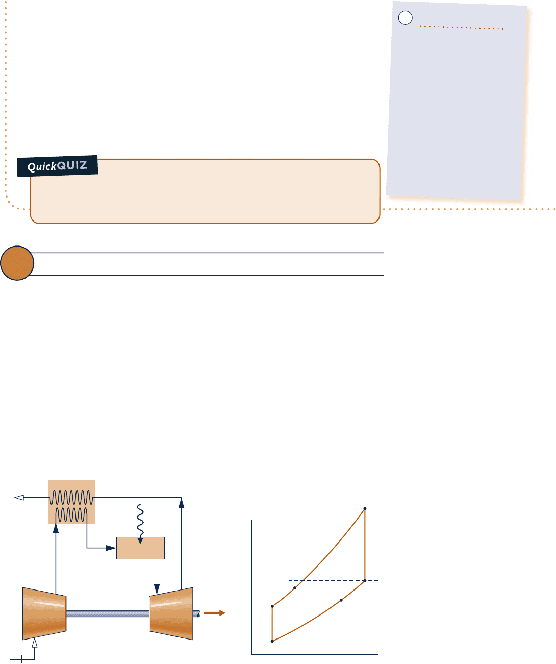
➊ The solution to this example on a cold air-standard basis is left as an
exercise.
➋ Irreversibilities within the turbine and compressor have a significant impact
on the performance of gas turbines. This is brought out by comparing
the results of the present example with those of Example 9.4. Irreversibili-
ties result in an increase in the work of compression and a reduction in
work output of the turbine. The back work ratio is greatly increased
and the thermal efficiency significantly decreased. Still, we should recog-
nize that the most significant irreversibility of gas turbines by far is com-
bustion irreversibility.
Ability to…
❑
sketch the schematic of
the basic air-standard gas
turbine and the T–s diagram
for the corresponding Bray-
ton cycle with compressor
and turbine irreversibilities.
❑
evaluate temperatures and
pressures at each principal
state and retrieve necessary
property data.
❑
calculate the thermal effi-
ciency and back work ratio.
✓Skills Developed
What would be the thermal efficiency and back work ratio
if the isentropic turbine efficiency were 70% keeping isentropic com-
pressor efficiency and other given data the same? Ans. h 5 16.8%, bwr 5
70.65%.
regenerator
9.7 Regenerative Gas Turbines
The turbine exhaust temperature of a simple gas turbine is normally well above the
ambient temperature. Accordingly, the hot turbine exhaust gas has significant ther-
modynamic utility (exergy) that would be irrevocably lost were the gas discarded
directly to the surroundings. One way of utilizing this potential is by means of a heat
exchanger called a regenerator, which allows the air exiting the compressor to be
preheated before entering the combustor, thereby reducing the amount of fuel that
must be burned in the combustor. The combined cycle arrangement considered in
Sec. 9.9 is another way to utilize the hot turbine exhaust gas.
An air-standard Brayton cycle modified to include a regenerator is illustrated in
Fig. 9.14. The regenerator shown is a counterflow heat exchanger through which the
hot turbine exhaust gas and the cooler air leaving the compressor pass in opposite
directions. Ideally, no frictional pressure drop occurs in either stream. The turbine
exhaust gas is cooled from state 4 to state y, while the air exiting the compressor is
heated from state 2 to state x. Hence, a heat transfer from a source external to the
9.7 Regenerative Gas Turbines 521
Fig. 9.14
Regenerative air-standard gas turbine cycle.
Combustor
1
x
234
y
TurbineCompressor
Q
·
in
W
·
cycle
Regenerator
T
s
1
2
3
4
y
x
c09GasPowerSystems.indd Page 521 7/19/10 9:50:26 AM users-133 c09GasPowerSystems.indd Page 521 7/19/10 9:50:26 AM users-133 /Users/users-133/Desktop/Ramakant_04.05.09/WB00113_R1:JWCL170/New/Users/users-133/Desktop/Ramakant_04.05.09/WB00113_R1:JWCL170/New

522 Chapter 9 Gas Power Systems
cycle is required only to increase the air temperature from state x to state 3, rather
than from state 2 to state 3, as would be the case without regeneration. The heat added
per unit of mass is then given by
Q
#
in
m
#
5 h
3
2 h
x
(9.26)
The net work developed per unit of mass flow is not altered by the addition of a
regenerator. Thus, since the heat added is reduced, the thermal efficiency increases.
REGENERATOR EFFECTIVENESS. From Eq. 9.26 it can be concluded that the
external heat transfer required by a gas turbine power plant decreases as the specific
enthalpy h
x
increases and thus as the temperature T
x
increases. Evidently, there is an
incentive in terms of fuel saved for selecting a regenerator that provides the greatest
practical value for this temperature. To consider the maximum theoretical value for
T
x
, refer to Fig. 9.15, which shows temperature variations of the hot and cold streams
of a counterflow heat exchanger.
c First, refer to Fig. 9.15a. Since a finite temperature difference between the streams
is required for heat transfer to occur, the temperature of the cold stream at each
location, denoted by the coordinate z, is less than that of the hot stream. In par-
ticular, the temperature of the colder stream as it exits the heat exchanger is less
than the temperature of the incoming hot stream. If the heat transfer area were
increased, providing more opportunity for heat transfer between the two streams,
there would be a smaller temperature difference at each location.
c In the limiting case of infinite heat transfer area, the temperature difference would
approach zero at all locations, as illustrated in Fig. 9.15b, and the heat transfer
would approach reversibility. In this limit, the exit temperature of the colder stream
would approach the temperature of the incoming hot stream. Thus, the highest
possible temperature that could be achieved by the colder stream is the tempera-
ture of the incoming hot gas.
Referring again to the regenerator of Fig. 9.14, we can conclude from the discus-
sion of Fig. 9.15 that the maximum theoretical value for the temperature T
x
is the
turbine exhaust temperature T
4
, obtained if the regenerator were operating reversibly.
The regenerator effectiveness, h
reg
, is a parameter that gauges the departure of an actual
Fig. 9.15
Temperature distributions in counterflow heat exchangers. (a) Actual. (b) Reversible.
ΔT
z
(a)(b)
z
Hot
Cold
T
hot, in
T
cold, out
T
hot, out
T
cold, in
ΔT → 0
z
Hot
Cold
T
hot, in
T
cold, in
Hotter
stream in
Colder
stream in
z
Colder
stream in
Hotter
stream in
c09GasPowerSystems.indd Page 522 7/19/10 9:50:28 AM users-133 c09GasPowerSystems.indd Page 522 7/19/10 9:50:28 AM users-133 /Users/users-133/Desktop/Ramakant_04.05.09/WB00113_R1:JWCL170/New/Users/users-133/Desktop/Ramakant_04.05.09/WB00113_R1:JWCL170/New
