Moran M.J., Shapiro H.N. Fundamentals of Engineering Thermodynamics
Подождите немного. Документ загружается.

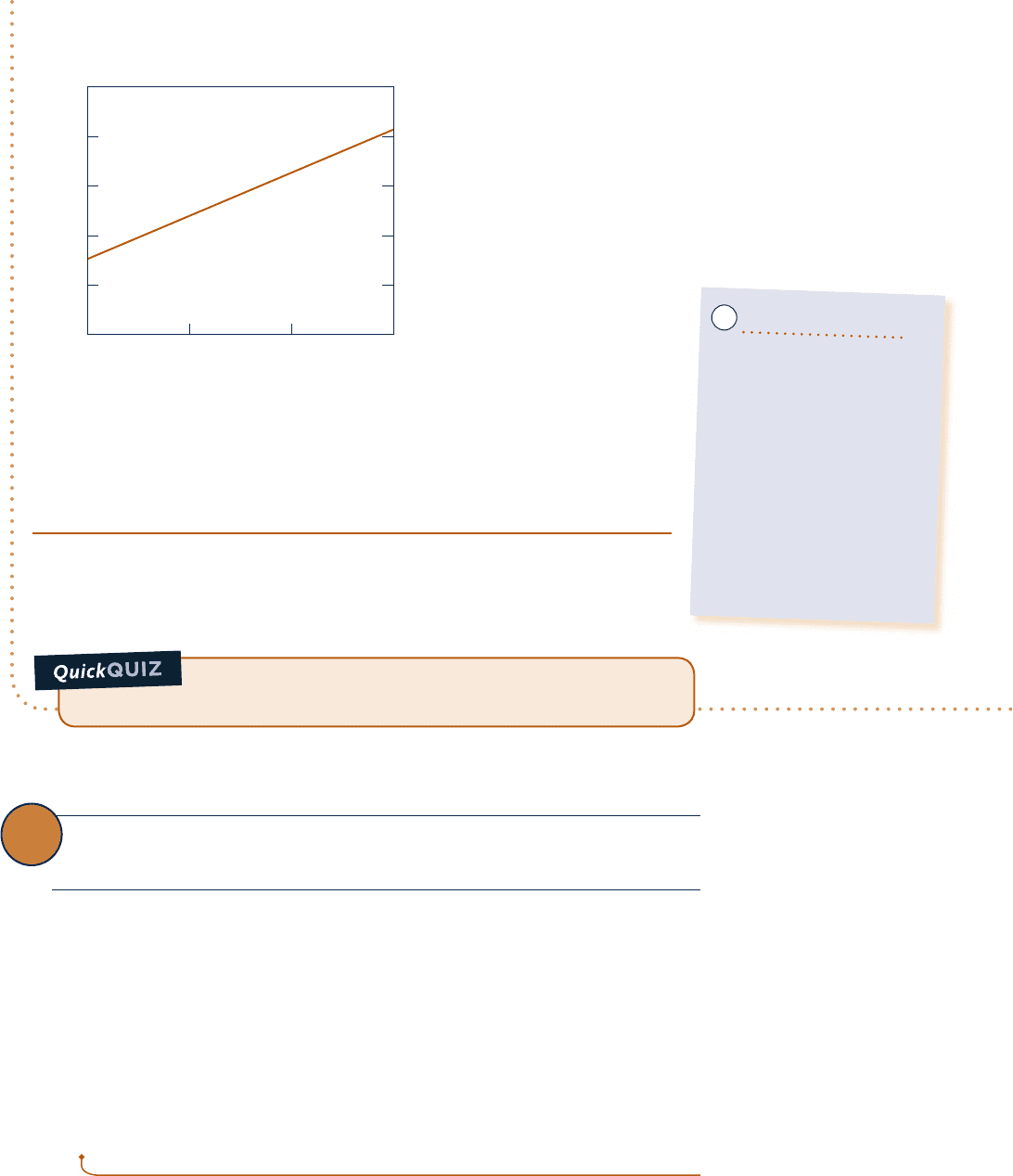
Using the Explore button, sweep eta from 0.85 to 1.0 in steps of 0.01. Then, using the Graph button, obtain the
following plot:
If the temperature T
3
were increased to 4808C, would you expect
the thermal efficiency to increase, decrease, or stay the same? Ans. Increase.
From Fig. E8.4b, we see that the cycle thermal efficiency increases from 0.351
to 0.403 as turbine stage isentropic efficiency increases from 0.85 to 1.00, as
expected based on the results of Example 8.3 and part (a) of the present exam-
ple. Turbine isentropic efficiency is seen to have a significant effect on cycle
thermal efficiency.
➊ Owing to the irreversibilities present in the turbine stages, the net work per
unit of mass developed in the present case is significantly less than in the
case of Example 8.3. The thermal efficiency is also considerably less.
Cycle thermal efficiency
0.42
0.40
0.38
0.36
0.34
0.32
1.000.95
Isentropic turbine efficiency
0.90
0.85
Fig. E8.4b
Ability to…
❑
sketch the T–s diagram of
the Rankine cycle with
reheat, including turbine and
pump irreversibilities.
❑
fix each of the principal
states and retrieve
necessary property data.
❑
apply mass, energy, and
entropy principles.
❑
calculate performance
parameters for the cycle.
✓
Skills Developed
8.4 Improving Performance—Regenerative
Vapor Power Cycle
Another commonly used method for increasing the thermal efficiency of vapor power
plants is regenerative feedwater heating, or simply regeneration. This is the subject of
the present section.
To introduce the principle underlying regenerative feedwater heating, consider
Fig. 8.3 once again. In cycle 1–2–3–4–a–1, the working fluid enters the boiler as a
compressed liquid at state 4 and is heated while in the liquid phase to state a. With
regenerative feedwater heating, the working fluid enters the boiler at a state between
4 and a. As a result, the average temperature of heat addition is increased, thereby
tending to increase the thermal efficiency.
8.4.1
Open Feedwater Heaters
Let us consider how regeneration can be accomplished using an open feedwater heater,
a direct contact-type heat exchanger in which streams at different temperatures mix
regeneration
open feedwater heater
8.4 Improving Performance—Regenerative Vapor Power Cycle 453
c08VaporPowerSystems.indd Page 453 7/12/10 6:59:40 AM user-s146c08VaporPowerSystems.indd Page 453 7/12/10 6:59:40 AM user-s146 /Users/user-s146/Desktop/Merry_X-Mas/New/Users/user-s146/Desktop/Merry_X-Mas/New
454 Chapter 8
Vapor Power Systems
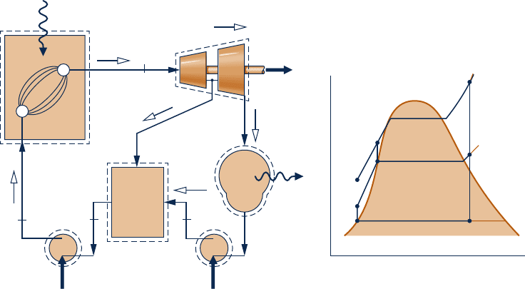
to form a stream at an intermediate temperature. Shown in Fig. 8.9 are the schematic
diagram and the associated T–s diagram for a regenerative vapor power cycle having
one open feedwater heater. For this cycle, the working fluid passes isentropically
through the turbine stages and pumps, and flow through the steam generator, con-
denser, and feedwater heater takes place with no pressure drop in any of these
components. Still, there is a source of irreversibility owing to mixing within the feed-
water heater.
Steam enters the first-stage turbine at state 1 and expands to state 2, where a frac-
tion of the total flow is extracted, or bled, into an open feedwater heater operating
at the extraction pressure, p
2
. The rest of the steam expands through the second-stage
turbine to state 3. This portion of the total flow is condensed to saturated liquid, state
4, and then pumped to the extraction pressure and introduced into the feedwater
heater at state 5. A single mixed stream exits the feedwater heater at state 6. For the
case shown in Fig. 8.9, the mass flow rates of the streams entering the feedwater
heater are such that state 6 is saturated liquid at the extraction pressure. The liquid
at state 6 is then pumped to the steam generator pressure and enters the steam gen-
erator at state 7. Finally, the working fluid is heated from state 7 to state 1 in the
steam generator.
Referring to the T–s diagram of the cycle, note that the heat addition would take
place from state 7 to state 1, rather than from state a to state 1, as would be the case
without regeneration. Accordingly, the amount of energy that must be supplied from
the combustion of a fossil fuel, or another source, to vaporize and superheat the steam
would be reduced. This is the desired outcome. Only a portion of the total flow
expands through the second-stage turbine (Process 2–3), however, so less work would
be developed as well. In practice, operating conditions are such that the reduction in
heat added more than offsets the decrease in net work developed, resulting in an
increased thermal efficiency in regenerative power plants.
Cycle Analysis
Consider next the thermodynamic analysis of the regenerative cycle illustrated in
Fig. 8.9. An important initial step in analyzing any regenerative vapor cycle is the
evaluation of the mass flow rates through each of the components. Taking a single
control volume enclosing both turbine stages, the mass rate balance reduces at steady
state to
m
#
2
1 m
#
3
5 m
#
1
Open
feedwater
heater
1
7
65
2
3
4
Pump 2 Pump 1
(1)
(y)
(1)
(1 – y)
(1 – y)
(1 – y)
Steam
generator
Condenser
Q
in
·
Q
out
·
W
p2
·
W
p1
·
W
t
·
T
s
a
5
4
7
6
1
2
3
Fig. 8.9 Regenerative vapor power cycle with one open feedwater heater.
c08VaporPowerSystems.indd Page 454 7/12/10 6:59:43 AM user-s146c08VaporPowerSystems.indd Page 454 7/12/10 6:59:43 AM user-s146 /Users/user-s146/Desktop/Merry_X-Mas/New/Users/user-s146/Desktop/Merry_X-Mas/New

where m
#
1
is the rate at which mass enters the first-stage turbine at state 1, m
#
2
is the
rate at which mass is extracted and exits at state 2, and m
#
3
is the rate at which mass
exits the second-stage turbine at state 3. Dividing by m
#
1
places this on the basis of a
unit of mass passing through the first-stage turbine
m
#
2
m
#
1
1
m
#
3
m
#
1
5 1
Denoting the fraction of the total flow extracted at state 2 by y
1
y 5 m
#
2
/
m
#
1
2
, the
fraction of the total flow passing through the second-stage turbine is
m
#
3
m
#
1
5 1 2 y
(8.11)
The fractions of the total flow at various locations are indicated in parentheses on
Fig. 8.9.
The fraction y can be determined by applying the conservation of mass and con-
servation of energy principles to a control volume around the feedwater heater.
Assuming no heat transfer between the feedwater heater and its surroundings and
ignoring kinetic and potential energy effects, the mass and energy rate balances
reduce at steady state to give
0 5 yh
2
1
1
1 2 y
2
h
5
2 h
6
Solving for y
y 5
h
6
2 h
5
h
2
2 h
5
(8.12)
Equation 8.12 allows the fraction y to be determined when states 2, 5, and 6 are fixed.
Expressions for the principal work and heat transfers of the regenerative cycle can
be determined by applying mass and energy rate balances to control volumes around
the individual components. Beginning with the turbine, the total work is the sum of the
work developed by each turbine stage. Neglecting kinetic and potential energy effects
and assuming no heat transfer with the surroundings, we can express the total turbine
work on the basis of a unit of mass passing through the first-stage turbine as
W
#
t
m
#
1
5 1h
1
2 h
2
21 11 2 y21h
2
2 h
3
2
(8.13)
The total pump work is the sum of the work required to operate each pump indi-
vidually. On the basis of a unit of mass passing through the first-stage turbine, the
total pump work is
W
#
p
m
#
1
5 1h
7
2 h
6
21 11 2 y21h
5
2 h
4
2
(8.14)
The energy added by heat transfer to the working fluid passing through the steam
generator, per unit of mass expanding through the first-stage turbine, is
Q
#
in
m
#
1
5 h
1
2 h
7
(8.15)
and the energy rejected by heat transfer to the cooling water is
Q
#
out
m
#
1
5 11 2 y21h
3
2 h
4
2
(8.16)
The following example illustrates the analysis of a regenerative cycle with one open
feedwater heater, including the evaluation of properties at state points around the
cycle and the determination of the fractions of the total flow at various locations.
8.4 Improving Performance—Regenerative Vapor Power Cycle 455
c08VaporPowerSystems.indd Page 455 7/12/10 6:59:45 AM user-s146c08VaporPowerSystems.indd Page 455 7/12/10 6:59:45 AM user-s146 /Users/user-s146/Desktop/Merry_X-Mas/New/Users/user-s146/Desktop/Merry_X-Mas/New
456 Chapter 8 Vapor Power Systems
Considering a Regenerative Cycle with Open Feedwater Heater
c c c c EXAMPLE 8.5 c
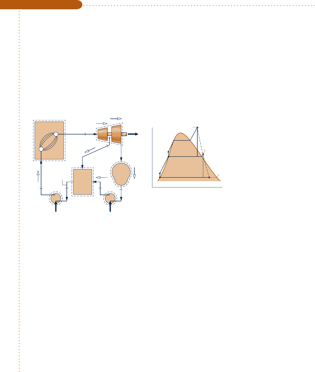
Consider a regenerative vapor power cycle with one open feedwater heater. Steam enters the turbine at 8.0 MPa,
4808C and expands to 0.7 MPa, where some of the steam is extracted and diverted to the open feedwater heater
operating at 0.7 MPa. The remaining steam expands through the second-stage turbine to the condenser pressure
of 0.008 MPa. Saturated liquid exits the open feedwater heater at 0.7 MPa. The isentropic efficiency of each tur-
bine stage is 85% and each pump operates isentropically. If the net power output of the cycle is 100 MW, deter-
mine (a) the thermal efficiency and (b) the mass flow rate of steam entering the first turbine stage, in kg/h.
SOLUTION
Known:
A regenerative vapor power cycle operates with steam as the working fluid. Operating pressures and tem-
peratures are specified; the isentropic efficiency of each turbine stage and the net power output are also given.
Find: Determine the thermal efficiency and the mass flow rate into the turbine, in kg/h.
Schematic and Given Data:
Engineering Model:
1.
Each component in the cycle is analyzed as a steady-state control volume. The control volumes are shown
in the accompanying sketch by dashed lines.
2. All processes of the working fluid are internally reversible, except for the expansions through the two tur-
bine stages and mixing in the open feedwater heater.
3. The turbines, pumps, and feedwater heater operate adiabatically.
4. Kinetic and potential energy effects are negligible.
5. Saturated liquid exits the open feedwater heater, and saturated liquid exits the condenser.
Analysis: The specific enthalpy at states 1 and 4 can be read from the steam tables. The specific enthalpy at state
2 is evaluated in the solution to Example 8.4. The specific entropy at state 2 can be obtained from the steam tables
using the known values of enthalpy and pressure at this state. In summary, h
1
5 3348.4 kJ/kg, h
2
5 2832.8 kJ/kg,
s
2
5 6.8606 kJ/kg
?
K, h
4
5 173.88 kJ/kg.
The specific enthalpy at state 3 can be determined using the isentropic efficiency of the second-stage turbine
h
3
5 h
2
2 h
t
1
h
2
2 h
3s
2
With s
3s
5 s
2
, the quality at state 3s is
x
3s
5 0.8208; using this, we get h
3s
5 2146.3 kJ
/
k
g
. Hence
h
3
5 2832.8 2 0.85
1
2832.8 2 2146.3
2
5 2249.3 kJ
/
kg
Open
feedwater
heater
1
7
65
2
3
4
Pump 2 Pump 1
(1)
(y)
(1)
(1 – y)
(1 – y)
(1 – y)
Steam
generator
Condenser
W
t
·
W
p2
·
W
p1
·
T
s
5
Saturated
liquid at
0.7 MPa
Saturated liquid
at 0.008 MPa
T
1
= 480°C
p
1
= 8.0 MPa
p
cond
=
0.008 MPa
T
1
7
6
2
1
2s
43s3
8.0 MPa
0.7 MPa
0.008 MPa
Fig. E8.5
➊
c08VaporPowerSystems.indd Page 456 7/12/10 7:00:13 AM user-s146 c08VaporPowerSystems.indd Page 456 7/12/10 7:00:13 AM user-s146 /Users/user-s146/Desktop/Merry_X-Mas/New/Users/user-s146/Desktop/Merry_X-Mas/New

8.4 Improving Performance—Regenerative Vapor Power Cycle 457
State 6 is saturated liquid at 0.7 MPa. Thus, h
6
5 697.22 kJ
/
kg.
Since the pumps operate isentropically, the specific enthalpy values at states 5 and 7 can be determined as
h
5
5 h
4
1 y
4
1
p
5
2 p
4
2
5 173.88 1 11.0084 3 10
23
21m
3
/
kg210.7 2 0.0082 MPa `
10
6
N
/
m
2
1 MPa
``
1 kJ
10
3
N ? m
`5 174.6 kJ
/
kg
h
7
5 h
6
1 y
6
1
p
7
2 p
6
2
5 697.22 1 11.1080 3 10
23
218.0 2 0.72
Z
10
3
Z
5 705.3 kJ
/
kg
Applying mass and energy rate balances to a control volume enclosing the open heater, we find the fraction y
of the flow extracted at state 2 from
y 5
h
6
2 h
5
h
2
2 h
5
5
697.22 2 174.6
2832.8 2 174.6
5 0.1966
(a) On the basis of a unit of mass passing through the first-stage turbine, the total turbine work output is
W
#
t
m
#
1
5 1h
1
2 h
2
21 11 2 y21h
2
2 h
3
2
5
1
3348.4 2 2832.8
2
1
1
0.8034
21
2832.8 2 2249.3
2
5 984.4 kJ
/
kg
The total pump work per unit of mass passing through the first-stage turbine is
W
#
p
m
#
1
5 1h
7
2 h
6
21 11 2 y21h
5
2 h
4
2
5
1
705.3 2 697.22
2
1
1
0.8034
21
174.6 2 173.88
2
5 8.7 kJ
/
kg
The heat added in the steam generator per unit of mass passing through the first-stage turbine is
Q
#
in
m
#
1
5 h
1
2 h
7
5 3348.4 2 705.3 5 2643.1 kJ
/
kg
The thermal efficiency is then
h 5
W
#
t
/
m
#
1
2 W
#
p
/
m
#
1
Q
#
in
/
m
#
1
5
984.4 2 8.7
2643.1
5 0.369 136.9%2
(b) The mass flow rate of the steam entering the turbine, m
#
1
, can be determined
using the given value for the net power output, 100 MW. Since
W
#
c
y
cle
5 W
#
t
2 W
#
p
and
W
#
t
m
#
1
5 984.4 kJ
/
kg
and
W
#
p
m
#
1
5 8.7 kJ
/
kg
it follows that
m
#
1
5
1100 MW2
Z
3600 s
/
h
Z
1
984.4 2 8.7
2
kJ
/
kg
`
10
3
kJ
/
s
1 MW
`5 3.69 3 10
5
kg
/
h
➊ Note that the fractions of the total flow at various locations are labeled on
the figure.
If the mass flow rate of steam entering the first-stage turbine
were 150 kg/s, what would be the net power, in MW, and the fraction of
steam extracted, y? Ans. 146.4 MW, 0.1966.
Ability to…
❑
sketch the T–s diagram of
the regenerative vapor
power cycle with one open
feedwater heater.
❑
fix each of the principal
states and retrieve neces-
sary property data.
❑
apply mass, energy, and
entropy principles.
❑
calculate performance
parameters for the cycle.
✓
Skills Developed
c08VaporPowerSystems.indd Page 457 7/12/10 7:00:17 AM user-s146 c08VaporPowerSystems.indd Page 457 7/12/10 7:00:17 AM user-s146 /Users/user-s146/Desktop/Merry_X-Mas/New/Users/user-s146/Desktop/Merry_X-Mas/New
458 Chapter 8
Vapor Power Systems
closed feedwater heater
To higher
pressure line
Feedwater
out
Feedwater
in
Extraction steam
Pump
To lower-
pressure heater
or condenser
Extraction steam
Condensate Condensate
Steam trap
(a)(b)
Fig. 8.10 Examples of closed feedwater heaters.
Fig. 8.11 Regenerative vapor power cycle with one closed feedwater heater.
W
t
·
1
(1)
(1) (1)
Steam
generator
Q
in
·
Q
out
·
W
p
·
Closed
feedwater
heater
(y)
(1 – y)
(y)
(y)
2
6
7
5
3
4
8
Trap
Condenser
Pump
T
s
5
6
48
7
2
1
3
(1 – y)
8.4.2
Closed Feedwater Heaters
Regenerative feedwater heating also can be accomplished with closed feedwater
heaters
. Closed heaters are shell-and-tube-type recuperators in which the feedwater
temperature increases as the extracted steam condenses on the outside of the tubes
carrying the feedwater. Since the two streams do not mix, they can be at different
pressures.
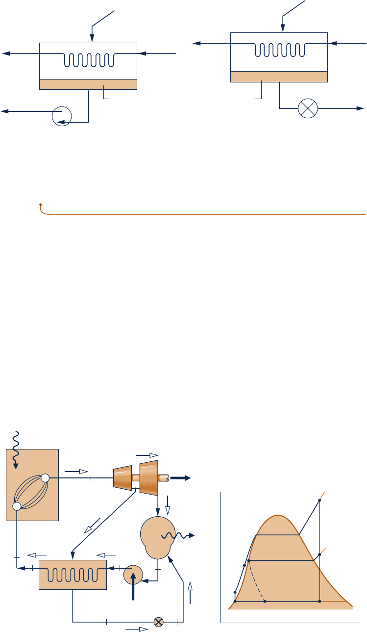
The diagrams of Fig. 8.10 show two different schemes for removing the condensate
from closed feedwater heaters. In Fig. 8.10a, this is accomplished by means of a pump
whose function is to pump the condensate forward to a higher-pressure point in the
cycle. In Fig. 8.10b, the condensate is allowed to expand through a trap into a feed-
water heater operating at a lower pressure or into the condenser. A trap is a type of
valve that permits only liquid to pass through to a region of lower pressure.
A regenerative vapor power cycle having one closed feedwater heater with the
condensate trapped into the condenser is shown schematically in Fig. 8.11. For this
cycle, the working fluid passes isentropically through the turbine stages and pumps.
Except for expansion through the trap, there are no pressure drops accompanying
c08VaporPowerSystems.indd Page 458 7/12/10 7:00:21 AM user-s146 c08VaporPowerSystems.indd Page 458 7/12/10 7:00:21 AM user-s146 /Users/user-s146/Desktop/Merry_X-Mas/New/Users/user-s146/Desktop/Merry_X-Mas/New

flow through other components. The T–s diagram shows the principal states of
the cycle.
The total steam flow expands through the first-stage turbine from state 1 to state
2. At this location, a fraction of the flow is bled into the closed feedwater heater,
where it condenses. Saturated liquid at the extraction pressure exits the feedwater
heater at state 7. The condensate is then trapped into the condenser, where it is
reunited with the portion of the total flow passing through the second-stage turbine.
The expansion from state 7 to state 8 through the trap is irreversible, so it is shown
by a dashed line on the T–s diagram. The total flow exiting the condenser as saturated
liquid at state 4 is pumped to the steam generator pressure and enters the feedwater
heater at state 5. The temperature of the feedwater is increased in passing through
the feedwater heater. The feedwater then exits at state 6. The cycle is completed as
the working fluid is heated in the steam generator at constant pressure from state 6
to state 1. Although the closed heater shown on the figure operates with no pressure
drop in either stream, there is a source of irreversibility due to the stream-to-stream
temperature difference.
Cycle Analysis
The schematic diagram of the cycle shown in Fig. 8.11 is labeled with the fractions
of the total flow at various locations. This is usually helpful in analyzing such cycles.
The fraction of the total flow extracted, y, can be determined by applying the con-
servation of mass and conservation of energy principles to a control volume around
the closed heater. Assuming no heat transfer between the feedwater heater and its
surroundings and neglecting kinetic and potential energy effects, the mass and energy
rate balances reduce at steady state to give
0 5 y
1
h
2
2 h
7
2
1
1
h
5
2 h
6
2
Solving for y
y 5
h
6
2 h
5
h
2
2 h
7
(8.17)
The principal work and heat transfers are evaluated as discussed previously.
deaeration
8.4.3
Multiple Feedwater Heaters
The thermal efficiency of the regenerative cycle can be increased by incorporating
several feedwater heaters at suitably chosen pressures. The number of feedwater heaters
used is based on economic considerations, since incremental increases in thermal
efficiency achieved with each additional heater must justify the added capital costs
(heater, piping, pumps, etc.). Power plant designers use computer programs to simu-
late the thermodynamic and economic performance of different designs to help them
decide on the number of heaters to use, the types of heaters, and the pressures at
which they should operate.
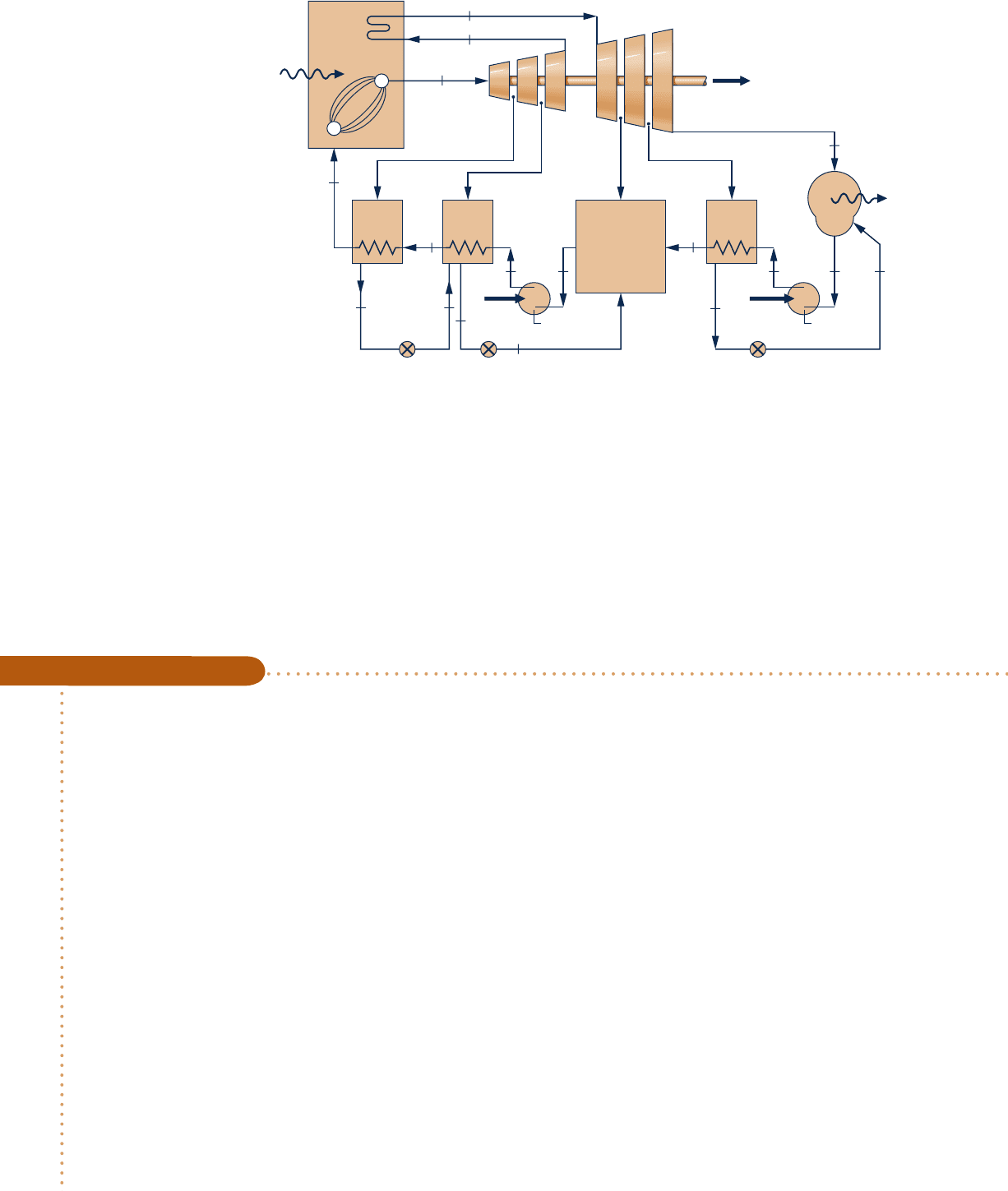
Figure 8.12 shows the layout of a power plant with three closed feedwater heaters
and one open heater. Power plants with multiple feedwater heaters ordinarily have
at least one open feedwater heater operating at a pressure greater than atmospheric
pressure so that oxygen and other dissolved gases can be vented from the cycle. This
procedure, known as deaeration, is needed to maintain the purity of the working fluid
in order to minimize corrosion. Actual power plants have many of the same basic
features as the one shown in the figure.
In analyzing regenerative vapor power cycles with multiple feedwater heaters, it is
good practice to base the analysis on a unit of mass entering the first-stage turbine.
To clarify the quantities of matter flowing through the various plant components, the
8.4 Improving Performance—Regenerative Vapor Power Cycle 459
c08VaporPowerSystems.indd Page 459 7/12/10 7:00:25 AM user-s146 c08VaporPowerSystems.indd Page 459 7/12/10 7:00:25 AM user-s146 /Users/user-s146/Desktop/Merry_X-Mas/New/Users/user-s146/Desktop/Merry_X-Mas/New
460 Chapter 8 Vapor Power Systems
fractions of the total flow removed at each extraction point and the fraction of the
total flow remaining at each state point in the cycle should be labeled on a schematic
diagram of the cycle. The fractions extracted are determined from mass and energy
rate balances for control volumes around each of the feedwater heaters, starting with
the highest-pressure heater and proceeding to each lower-pressure heater in turn. This
procedure is used in the next example that involves a reheat–regenerative vapor
power cycle with two feedwater heaters, one open feedwater heater and one closed
feedwater heater.
Steam
generator
5
4
1
2
6
7
3
21
15
14
16
17
13 12
19
10 9
8
20
11
18
Closed
heater
Closed
heater
Closed
heater
Main boiler
feed pump
Condensate
pump
Deaerating
open
heater
Condenser
W
t
·
W
p1
·
W
p2
·
Q
ou
t
·
Q
in
·
Fig. 8.12 Example of a power plant layout.
Considering a Reheat–Regenerative Cycle with Two Feedwater Heaters
c c c c EXAMPLE 8.6 c
Consider a reheat–regenerative vapor power cycle with two feedwater heaters, a closed feedwater heater and an
open feedwater heater. Steam enters the first turbine at 8.0 MPa, 4808C and expands to 0.7 MPa. The steam is
reheated to 4408C before entering the second turbine, where it expands to the condenser pressure of 0.008 MPa.
Steam is extracted from the first turbine at 2 MPa and fed to the closed feedwater heater. Feedwater leaves the
closed heater at 2058C and 8.0 MPa, and condensate exits as saturated liquid at 2 MPa. The condensate is trapped
into the open feedwater heater. Steam extracted from the second turbine at 0.3 MPa is also fed into the open
feedwater heater, which operates at 0.3 MPa. The stream exiting the open feedwater heater is saturated liquid
at 0.3 MPa. The net power output of the cycle is 100 MW. There is no stray heat transfer from any component
to its surroundings. If the working fluid experiences no irreversibilities as it passes through the turbines, pumps,
steam generator, reheater, and condenser, determine (a) the thermal efficiency, (b) the mass flow rate of the
steam entering the first turbine, in kg/h.
SOLUTION
Known:
A reheat–regenerative vapor power cycle operates with steam as the working fluid. Operating pressures
and temperatures are specified, and the net power output is given.
Find: Determine the thermal efficiency and the mass flow rate entering the first turbine, in kg/h.
c08VaporPowerSystems.indd Page 460 7/12/10 7:00:26 AM user-s146 c08VaporPowerSystems.indd Page 460 7/12/10 7:00:26 AM user-s146 /Users/user-s146/Desktop/Merry_X-Mas/New/Users/user-s146/Desktop/Merry_X-Mas/New
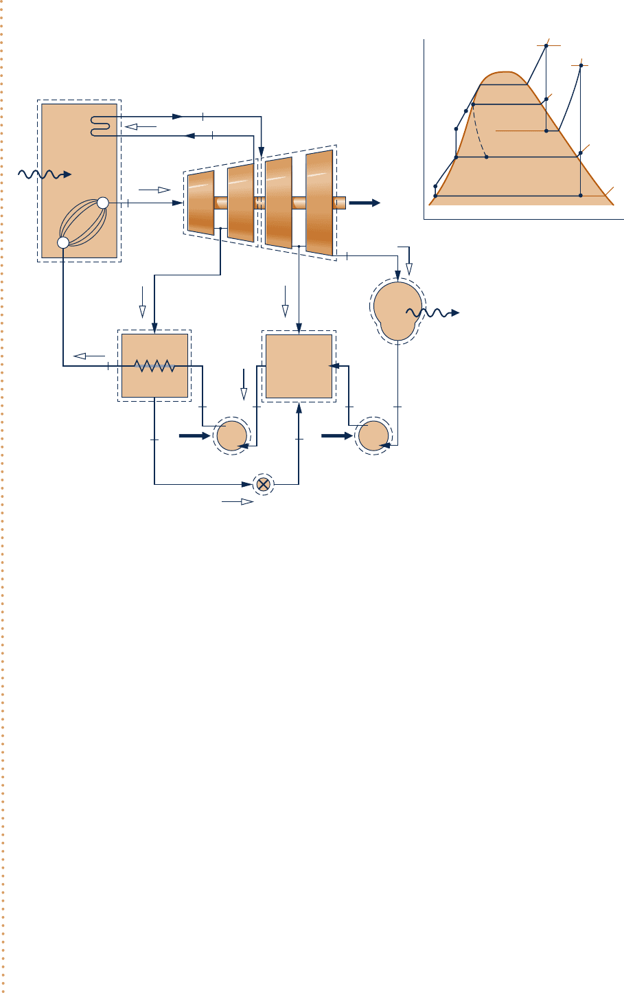
Schematic and Given Data:
Engineering Model:
1.
Each component in the cycle is analyzed as a control volume at steady state. The control volumes are
shown on the accompanying sketch by dashed lines.
2. There is no stray heat transfer from any component to its surroundings.
3. The working fluid undergoes internally reversible processes as it passes through the turbines, pumps,
steam generator, reheater, and condenser.
4. The expansion through the trap is a throttling process.
5. Kinetic and potential energy effects are negligible.
6. Condensate exits the closed heater as a saturated liquid at 2 MPa. Feedwater exits the open heater as a
saturated liquid at 0.3 MPa. Condensate exits the condenser as a saturated liquid.
Analysis: Let us determine the specific enthalpies at the principal states of the cycle. State 1 is the same as in
Example 8.3, so h
1
5 3348.4 kJ/kg and s
1
5 6.6586 kJ/kg ? K.
State 2 is fixed by p
2
5 2.0 MPa and the specific entropy s
2
, which is the same as that of state 1. Interpolating
in Table A-4, we get h
2
5 2963.5 kJ/kg. The state at the exit of the first turbine is the same as at the exit of the
first turbine of Example 8.3, so h
3
5 2741.8 kJ/kg.
State 4 is superheated vapor at 0.7 MPa, 4408C. From Table A-4, h
4
5 3353.3 kJ/kg and s
4
5 7.7571 kJ/kg ? K.
Interpolating in Table A-4 at p
5
5 0.3 MPa and s
5
5 s
4
5 7.7571 kJ/kg ? K, the enthalpy at state 5 is h
5
5 3101.5
kJ/kg.
Steam
generator
Q
in
·
Q
out
·
W
t
·
W
p1
·
(1 – y' – y'')
(1 – y´)
Condenser
0.008 MPa
6
5
2
4
1
3
T
4
= 440°C
T
1
= 480°C
T
1
= 480°C
T
11
= 205°C
T
4
= 440°C
(y')
(y'')
(1)
(1)
11
12 13
87
10 9
(1)
Pump 2 Pump 1
Closed
heater
Open
heater
0.3 MPa
2.0 MPa
Trap
(y
')
1
4
2
11
10
8
913
7
5
3
6
12
8.0 MPa
2.0 MPa
0.7 MPa
0.3 MPa
0.008 MPa
T
s
W
p2
·
Fig. E8.6
8.4 Improving Performance—Regenerative Vapor Power Cycle 461
c08VaporPowerSystems.indd Page 461 7/12/10 7:00:28 AM user-s146 c08VaporPowerSystems.indd Page 461 7/12/10 7:00:28 AM user-s146 /Users/user-s146/Desktop/Merry_X-Mas/New/Users/user-s146/Desktop/Merry_X-Mas/New

462 Chapter 8
Vapor Power Systems
Using s
6
5 s
4
, the quality at state 6 is found to be x
6
5 0.9382. So
h
6
5 h
f
1 x
6
h
f
g
5 173.88 1
1
0.9382
2
2403.1 5 2428.5 kJ
/
kg
At the condenser exit, h
7
5 173.88 kJ/kg. The specific enthalpy at the exit of the first pump is
h
8
5 h
7
1 y
7
1
p
8
2 p
7
2
5 173.88 1
1
1.0084
21
0.3 2 0.008
2
5 174.17 kJ
/
kg
The required unit conversions were considered in previous examples.
The liquid leaving the open feedwater heater at state 9 is saturated liquid at 0.3 MPa. The specific enthalpy
is h
9
5 561.47 kJ/kg. The specific enthalpy at the exit of the second pump is
h
10
5 h
9
1 y
9
1
p
10
2 p
9
2
5 561.47 1
1
1.0732
21
8.0 2 0.3
2
5 569.73 kJ
/
kg
The condensate leaving the closed heater is saturated at 2 MPa. From Table A-3, h
12
5 908.79 kJ/kg. The fluid
passing through the trap undergoes a throttling process, so h
13
5 908.79 kJ/kg.
The specific enthalpy of the feedwater exiting the closed heater at 8.0 MPa and 2058C is found using Eq. 3.13 as
h
11
5 h
f
1 y
f
1
p
11
2 p
sat
2
5 875.1 1
1
1.1646
21
8.0 2 1.73
2
5 882.4 kJ
/
kg
where h
f
and y
f
are the saturated liquid specific enthalpy and specific volume at 2058C, respectively, and p
sat
is
the saturation pressure in MPa at this temperature. Alternatively, h
11
can be found from Table A-5.
The schematic diagram of the cycle is labeled with the fractions of the total flow into the turbine that remain
at various locations. The fractions of the total flow diverted to the closed heater and open heater, respectively,
are
y¿
5 m
#
2
/
m
#
1
and
y–
5 m
#
5
/
m
#
1
, where m
#
1
denotes the mass flow rate entering the first turbine.
The fraction y9 can be determined by application of mass and energy rate balances to a control volume enclos-
ing the closed heater. The result is
y¿ 5
h
11
2 h
10
h
2
2 h
12
5
882.4 2 569.73
2963.5 2 908.79
5 0.1522
The fraction y0 can be determined by application of mass and energy rate balances to a control volume enclosing
the open heater, resulting in
0 5 y–h
5
1
1
1 2 y¿ 2 y–
2
h
8
1 y¿h
13
2 h
9
Solving for y0
y
– 5
1
1 2 y¿
2
h
8
1 y¿h
13
2 h
9
h
8
2 h
5
5
1
0.8478
2
174.17 1
1
0.1522
2
908.79 2 561.47
174.17 2
3
1
0
1.
5
5
0
.
0941
(a) The following work and heat transfer values are expressed on the basis of a unit mass entering the first
turbine. The work developed by the first turbine per unit of mass entering is the sum
W
#
t1
m
#
1
5 1h
1
2 h
2
21 11 2 y¿21h
2
2 h
3
2
5
1
3348.4 2 2963.5
2
1
1
0.8478
21
2963.5 2 2741.8
2
5 572.9 kJ
/
k
g
Similarly, for the second turbine
W
#
t2
m
#
1
5 11 2 y¿21h
4
2 h
5
21 11 2 y¿ 2 y–21h
5
2 h
6
2
5
1
0.8478
21
3353.3 2 3101.5
2
1
1
0.7537
21
3101.5 2 2428.5
2
5 720.7 kJ
/
k
g
c08VaporPowerSystems.indd Page 462 7/12/10 7:00:30 AM user-s146 c08VaporPowerSystems.indd Page 462 7/12/10 7:00:30 AM user-s146 /Users/user-s146/Desktop/Merry_X-Mas/New/Users/user-s146/Desktop/Merry_X-Mas/New
