Moran M.J., Shapiro H.N. Fundamentals of Engineering Thermodynamics
Подождите немного. Документ загружается.

The term on the left of Eq. 7.23 is the decrease in flow exergy from turbine inlet
to exit. The equation shows that the flow exergy decrease is accounted for by the
turbine work developed, W
#
cv
/
m
#
, and the exergy destroyed, E
#
d
/
m
#
. A parameter that
gauges how effectively the flow exergy decrease is converted to the desired product
is the exergetic turbine efficiency
e 5
W
#
cv
/
m
#
e
f1
2 e
f2
(7.24)
This particular exergetic efficiency is sometimes referred to as the turbine effective-
ness. Carefully note that the exergetic turbine efficiency is defined differently from
the isentropic turbine efficiency introduced in Sec. 6.12.
the exergetic efficiency of the turbine considered in Example 6.11
is 81.2% when T
0
= 298 K. It is left as an exercise to verify this value. b b b b b
Compressors and Pumps
For a compressor or pump operating at steady state with no heat transfer with its
surroundings, the exergy rate balance, Eq. 7.17, can be placed in the form
a
2
W
#
cv
m
#
b
5 e
f2
2 e
f1
1
E
#
d
m
#
Thus, the exergy input to the device, 2W
#
cv
/
m
#
, is accounted for by the increase in the
flow exergy between inlet and exit and the exergy destroyed. The effectiveness of the
conversion from work input to flow exergy increase is gauged by the exergetic com-
pressor (or pump) efficiency
e 5
e
f2
2
e
f1
1
2W
#
cv
/
m
#
2
(7.25)
the exergetic efficiency of the compressor considered in Example
6.14 is 84.6% when T
0
5 273 K. It is left as an exercise to verify this value. b b b b b
Heat Exchanger Without Mixing
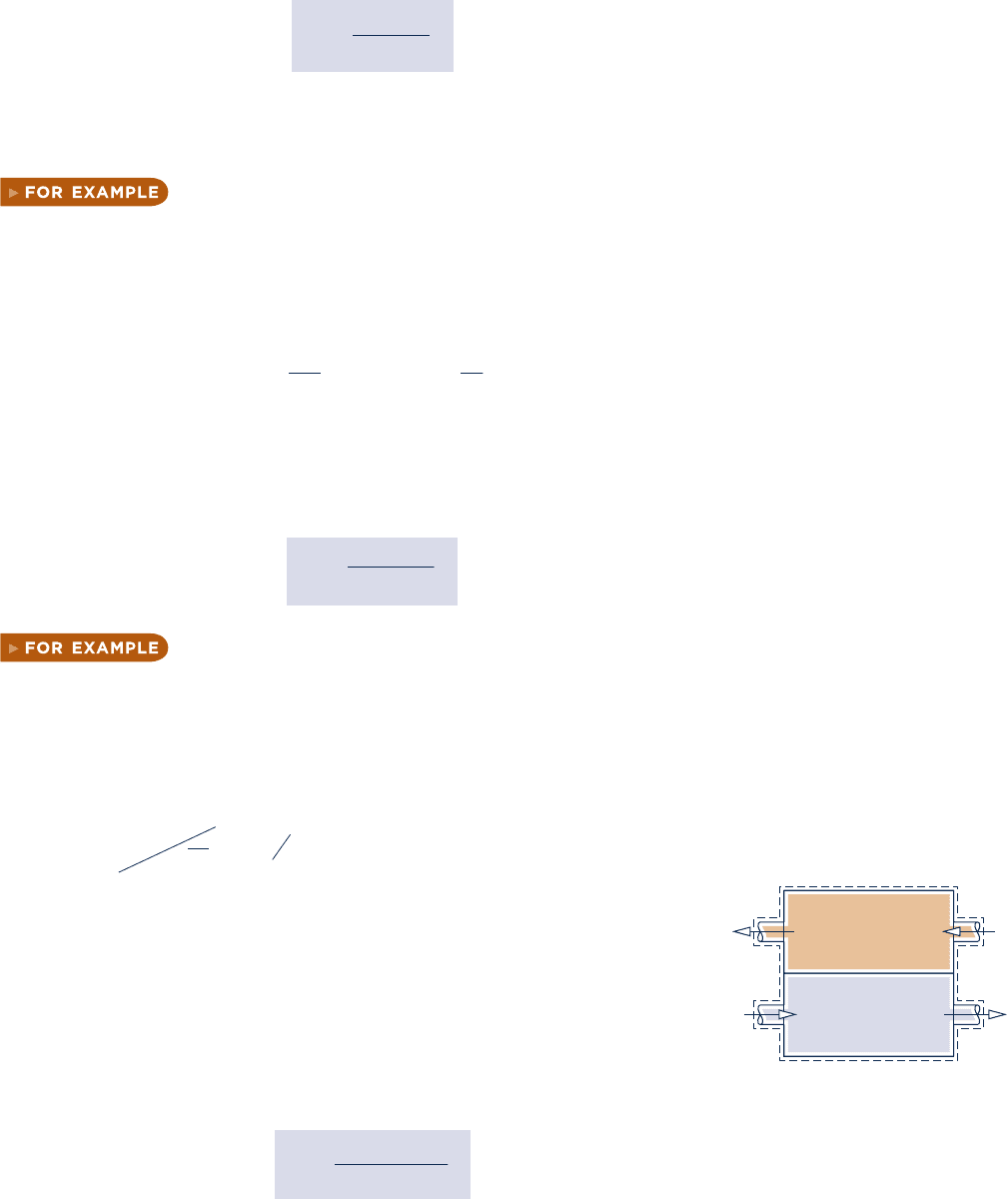
The heat exchanger shown in Fig. 7.10 operates at steady state with no heat transfer
with its surroundings and both streams at temperatures above T
0
. The exergy rate
balance, Eq. 7.13a, reduces to
0 5
a
j
a1 2
T
0
T
j
b
0
Q
#
j
2 W
#
0
cv
1
1
m
#
h
e
f1
1 m
#
c
e
f3
2
2
1
m
#
h
e
f2
1 m
#
c
e
f4
2
2 E
#
d
where m
#
h
is the mass flow rate of the hot stream and m
#
c
is the mass flow
rate of the cold stream. This can be rearranged to read
m
#
h
1
e
f1
2 e
f2
2
5 m
#
c
1
e
f4
2 e
f3
2
1 E
#
d
(7.26)
The term on the left of Eq. 7.26 accounts for the decrease in the exergy of
the hot stream. The first term on the right accounts for the increase in exergy
of the cold stream. Regarding the hot stream as supplying the exergy increase
of the cold stream as well as the exergy destroyed, we can write an exergetic
heat exchanger efficiency as
e 5
m
#
c
1
e
f4
2 e
f3
2
m
#
h
1
e
f1
2 e
f2
2
(7.27)
Hot
stream,
m
·
h
Cold
stream,
m
·
c
21
34
Fig. 7.10 Counterflow heat exchanger.
7.6 Exergetic (Second Law) Efficiency 393
c07ExergyAnalysis.indd Page 393 7/12/10 6:55:19 AM user-s146 c07ExergyAnalysis.indd Page 393 7/12/10 6:55:19 AM user-s146 /Users/user-s146/Desktop/Merry_X-Mas/New/Users/user-s146/Desktop/Merry_X-Mas/New
394 Chapter 7
Exergy Analysis
the exergetic efficiency of the heat exchanger of Example 7.6 is
83.3%. It is left as an exercise to verify this value. b b b b b
Direct Contact Heat Exchanger
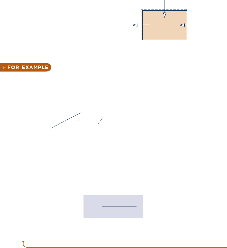
The direct contact heat exchanger shown in Fig. 7.11 operates at steady state with no
heat transfer with its surroundings. The exergy rate balance, Eq. 7.13a, reduces to
0 5
a
j
a1 2
T
0
T
j
b
0
Q
#
j
2 W
#
0
cv
1 m
#
1
e
f1
1 m
#
2
e
f2
2 m
#
3
e
f3
2 E
#
d
With m
#
3
5 m
#
1
1 m
#
2
from a mass rate balance, this can be written as
m
#
1
1e
f1
2 e
f3
25 m
#
2
1e
f3
2 e
f2
21 E
#
d
(7.28)
The term on the left of Eq. 7.28 accounts for the decrease in the exergy of the hot
stream between inlet and exit. The first term on the right accounts for the increase in
the exergy of the cold stream between inlet and exit. Regarding the hot stream as sup-
plying the exergy increase of the cold stream as well as the exergy destroyed by irre-
versibilities, we can write an exergetic efficiency for a direct contact heat exchanger as
e 5
m
#
2
1
e
f3
2 e
f2
2
m
#
1
1
e
f1
2 e
f3
2
(7.29)
1
2
Hot stream, m
1
·
Cold stream, m
2
·
Mixed stream, m
3
·
3
Fig. 7.11 Direct contact heat exchanger.
7.6.3
Using Exergetic Efficiencies
Exergetic efficiencies are useful for distinguishing means for utilizing fossil fuels that
are thermodynamically effective from those that are less so. Exergetic efficiencies also
can be used to evaluate the effectiveness of engineering measures taken to improve
the performance of systems. This is done by comparing the efficiency values deter-
mined before and after modifications have been made to show how much improve-
ment has been achieved. Moreover, exergetic efficiencies can be used to gauge the
potential for improvement in the performance of a given system by comparing the
efficiency of the system to the efficiency of like systems. A significant difference
between these values signals that improved performance is possible.
It is important to recognize that the limit of 100% exergetic efficiency should not
be regarded as a practical objective. This theoretical limit could be attained only if
there were no exergy destructions or losses. To achieve such idealized processes might
require extremely long times to execute processes and/or complex devices, both of
which are at odds with the objective of cost-effective operation. In practice, decisions
are chiefly made on the basis of total costs. An increase in efficiency to reduce fuel
consumption, or otherwise utilize fuels better, often requires additional expenditures
for facilities and operations. Accordingly, an improvement might not be implemented
if an increase in total cost would result. The trade-off between fuel savings and addi-
tional investment invariably dictates a lower efficiency than might be achieved theo-
retically and even a lower efficiency than could be achieved using the best available
technology.
c07ExergyAnalysis.indd Page 394 7/12/10 6:55:23 AM user-s146 c07ExergyAnalysis.indd Page 394 7/12/10 6:55:23 AM user-s146 /Users/user-s146/Desktop/Merry_X-Mas/New/Users/user-s146/Desktop/Merry_X-Mas/New

ENERGY & ENVIRONMENT A type of exergetic efficiency known as the
well-to-wheel efficiency is used to compare different options for powering vehicles.
The calculation of this efficiency begins at the well where the oil or natural gas feed-
stock is extracted from the ground and ends with the power delivered to a vehicle’s wheels. The
efficiency accounts separately for how effectively the vehicle’s fuel is produced from feedstock,
called the well-to-fuel tank efficiency, and how effectively the vehicle’s power plant converts its
fuel to power, called the fuel tank-to-wheel efficiency. The product of these gives the overall well-
to-wheel efficiency.
The table below gives sample well-to-wheel efficiency values for three power plant options as
reported by an automobile manufacturer:
Well-to-Tank Tank-to-Wheel Well-to-Wheel
(Fuel Production Efficiency) 3 (Vehicle Efficiency) 5 (Overall Efficiency)
(%) (%) (%)
Conventional
gasoline-fueled
engine 88 3 16 5 14
Hydrogen-fueled
fuel cell
a
58 3 38 5 22
Gasoline-fueled
hybrid electric 88 3 32 5 28
a
Hydrogen produced from natural gas.
These data show that vehicles using conventional internal combustion engines do not fare well
in terms of the well-to-wheel efficiency. The data also show that fuel-cell vehicles operating on
hydrogen have the best tank-to-wheel efficiency of the three options, but lose out on an overall
basis to hybrid vehicles, which enjoy a higher well-to-tank efficiency. Still, the well-to-wheel effi-
ciency is just one consideration when making policy decisions concerning different options for
powering vehicles. With increasing concern over global atmospheric CO
2
concentrations, another
consideration is the well-to-wheel total production of CO
2
in kg per km driven (lb per mile driven).
7.7 Thermoeconomics
Thermal systems typically experience significant work and/or heat interactions with
their surroundings, and they can exchange mass with their surroundings in the form
of hot and cold streams, including chemically reactive mixtures. Thermal systems
appear in almost every industry, and numerous examples are found in our everyday
lives. Their design and operation involve the application of principles from thermo-
dynamics, fluid mechanics, and heat transfer, as well as such fields as materials, man-
ufacturing, and mechanical design. The design and operation of thermal systems also
require explicit consideration of engineering economics, for cost is always a consid-
eration. The term thermoeconomics may be applied to this general area of application,
although it is often applied more narrowly to methodologies combining exergy and
economics for optimization studies during design of new systems and process improve-
ment of existing systems.
7.7.1
Costing
Is costing an art or a science? The answer is a little of both. Cost engineering is
an important engineering subdiscipline aimed at objectively applying real-world
thermoeconomics
7.7 Thermoeconomics 395
c07ExergyAnalysis.indd Page 395 7/12/10 6:55:26 AM user-s146 c07ExergyAnalysis.indd Page 395 7/12/10 6:55:26 AM user-s146 /Users/user-s146/Desktop/Merry_X-Mas/New/Users/user-s146/Desktop/Merry_X-Mas/New
396 Chapter 7
Exergy Analysis
costing experience in engineering design and project management. Costing services
are provided by practitioners skilled in the use of specialized methodologies, cost
models, and databases, together with costing expertise and judgment garnered from
years of professional practice. Depending on need, cost engineers provide services
ranging from rough and rapid estimates to in-depth analyses. Ideally, cost engineers
are involved with projects from the formative stages, for the output of cost engi-
neering is an essential input to decision making. Such input can be instrumental
in identifying feasible options from a set of alternatives and even pinpointing the
best option.
Costing of thermal systems considers costs of owning and operating them. Some
observers voice concerns that costs related to the environment often are only weakly
taken into consideration in such evaluations. They say companies pay for the right
to extract natural resources used in the production of goods and services but rarely
pay fully for depleting nonrenewable resources and mitigating accompanying envi-
ronmental degradation and loss of wildlife habitat, in many cases leaving the cost
burden to future generations. Another concern is who pays for the costs of control-
ling air and water pollution, cleaning up hazardous wastes, and the impacts of pol-
lution and waste on human health—industry, government, the public, or some com-
bination of each? Yet when agreement about environmental costs is achieved among
interested business, governmental, and advocacy groups, such costs are readily inte-
grated in costing of thermal systems, including costing on an exergy basis, which is
the present focus.
7.7.2
Using Exergy in Design
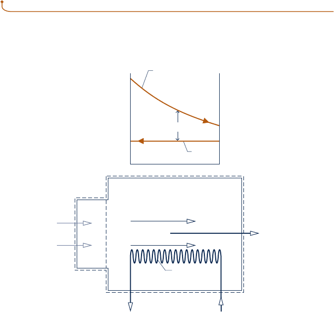
To illustrate the use of exergy reasoning in design, consider Fig. 7.12 showing a boiler
at steady state. Fuel and air enter the boiler and react to form hot combustion gases.
Combustion
gases
Water
Temperature
Combustion
gases
Fuel
Air
Steam,
saturated vapor
m
w
·
Feedwater,
saturated liquid
Boiler
tubes
ΔT
ave
Fig. 7.12 Boiler used to discuss exergy in design.
c07ExergyAnalysis.indd Page 396 7/12/10 6:55:26 AM user-s146 c07ExergyAnalysis.indd Page 396 7/12/10 6:55:26 AM user-s146 /Users/user-s146/Desktop/Merry_X-Mas/New/Users/user-s146/Desktop/Merry_X-Mas/New
Feedwater also enters as saturated liquid, receives exergy by heat transfer from the
combustion gases, and exits without temperature change as saturated vapor at a spec-
ified condition for use elsewhere. Temperatures of the hot gas and water streams are
also shown on the figure.
There are two main sources of exergy destruction in the boiler: (1) irreversible
heat transfer occurring between the hot combustion gases and the water flowing
through the boiler tubes, and (2) the combustion process itself. To simplify the pres-
ent discussion, the boiler is considered to consist of a combustor unit in which fuel
and air are burned to produce hot combustion gases, followed by a heat exchanger
unit where water is vaporized as the hot gases cool.
The present discussion centers on the heat exchanger unit. Let us think about
its total cost as the sum of fuel-related and capital costs. We will also take the aver-
age temperature difference between the two streams, DT
ave
, as the design variable.
From our study of the second law of thermodynamics, we know that the average
temperature difference between the two streams is a measure of exergy destruction
associated with heat transfer between them. The exergy destroyed owing to heat
transfer originates in the fuel entering the boiler. Accordingly, a cost related to fuel
consumption can be attributed to this source of irreversibility. Since exergy destruc-
tion increases with temperature difference between the streams, the fuel-related cost
increases with increasing DT
ave
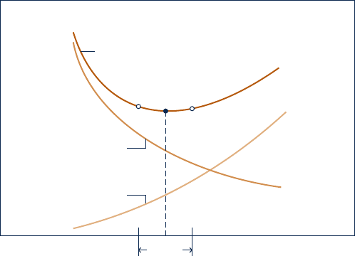
. This variation is shown in Fig. 7.13 on an annualized
basis, in dollars per year.
From our study of heat transfer, we know an inverse relation exits between DT
ave
and the boiler tube surface area required for a desired heat transfer rate between the
streams. For example, if we design for a small average temperature difference to
reduce exergy destruction within the heat exchanger, this dictates a large surface area
and typically a more costly boiler. From such considerations, we infer that boiler
capital cost increases with decreasing DT
ave
. This variation is shown in Fig. 7.13, again
on an annualized basis.
The total cost is the sum of the capital cost and the fuel cost. The total cost curve
shown in Fig. 7.13 exhibits a minimum at the point labeled a. Notice, however, that the
curve is relatively flat in the neighborhood of the minimum, so there is a range of
DT
ave
values that could be considered nearly optimal from the standpoint of minimum
total cost. If reducing the fuel cost were deemed more important than minimizing the
Nearly
optimal
a´
a´´
a
Capital cost
Fuel cost
Annualized cost, dollars per year
0
0
Average temperature difference, ΔT
ave
Total cost = Capital cost + Fuel cost
Fig. 7.13 Cost curves for the heat exchanger unit of the boiler of Fig. 7.12.
7.7 Thermoeconomics 397
c07ExergyAnalysis.indd Page 397 7/12/10 6:55:29 AM user-s146 c07ExergyAnalysis.indd Page 397 7/12/10 6:55:29 AM user-s146 /Users/user-s146/Desktop/Merry_X-Mas/New/Users/user-s146/Desktop/Merry_X-Mas/New
398 Chapter 7
Exergy Analysis
capital cost, we might choose a design that would operate at point a9. Point a0 would
be a more desirable operating point if capital cost were of greater concern. Such
trade-offs are common in design situations.
The actual design process differs significantly from the simple case considered
here. For one thing, costs cannot be determined as precisely as implied by the
curves in Fig. 7.13. Fuel prices vary widely over time, and equipment costs may be
difficult to predict as they often depend on a bidding procedure. Equipment is
manufactured in discrete sizes, so the cost also would not vary continuously as
shown in the figure. Furthermore, thermal systems usually consist of several com-
ponents that interact with one another. Optimization of components individually,
as considered for the heat exchanger unit of the boiler, does not guarantee an
optimum for the overall system. Finally, the example involves only DT
ave
as a
design variable. Often, several design variables must be considered and optimized
simultaneously.
7.7.3
Exergy Costing of a Cogeneration System
Another important aspect of thermoeconomics is the use of exergy for allocating
costs to the products of a thermal system. This involves assigning to each product
the total cost to produce it, namely the cost of fuel and other inputs plus the cost
of owning and operating the system (e.g., capital cost, operating and maintenance
costs). Such costing is a common problem in plants where utilities such as electrical
power, chilled water, compressed air, and steam are generated in one department
and used in others. The plant operator needs to know the cost of generating each
utility to ensure that the other departments are charged properly according to the
type and amount of each utility used. Common to all such considerations are fun-
damentals from engineering economics, including procedures for annualizing costs,
appropriate means for allocating costs, and reliable cost data.
To explore further the costing of thermal systems, consider the simple cogenera-
tion system operating at steady state shown in Fig. 7.14. The system consists of a
boiler and a turbine, with each having no significant heat transfer to its surround-
ings. The figure is labeled with exergy transfer rates associated with the flowing
streams, where the subscripts F, a, P, and w denote fuel, combustion air, combustion
products, and feedwater, respectively. The subscripts 1 and 2 denote high- and
low-pressure steam, respectively. Means for evaluating the exergies of the fuel and
combustion products are introduced in Chap. 13. The cogeneration system has two
principal products: electricity, denoted by W
#
e
, and low-pressure steam for use in
some process. The objective is to determine the cost at which each product is
generated.
High-pressure
steam
Low-pressure stea
m
W
e
, c
e
·
Turbine-electric
generator
Boiler
Fuel
Air
Feedwater
Combustion
products
Z
b
·
Z
t
·
2
E
fP
·
E
fa
·
E
fw
·
E
f1
, c
1
·
E
f2
, c
2
·
E
fF
, c
F
·
1
Fig. 7.14 Simple cogeneration
system.
c07ExergyAnalysis.indd Page 398 7/12/10 6:55:31 AM user-s146 c07ExergyAnalysis.indd Page 398 7/12/10 6:55:31 AM user-s146 /Users/user-s146/Desktop/Merry_X-Mas/New/Users/user-s146/Desktop/Merry_X-Mas/New

Boiler Analysis
Let us begin by evaluating the cost of the high-pressure steam produced by the boiler.
For this, we consider a control volume enclosing the boiler. Fuel and air enter the
boiler separately and combustion products exit. Feedwater enters and high-pressure
steam exits. The total cost to produce the exiting high-pressure steam equals the total
cost of the entering streams plus the cost of owning and operating the boiler. This is
expressed by the following
cost rate balance for the boiler
C
#
1
5 C
#
F
1 C
#
a
1 C
#
w
1 Z
#
b
(7.30)
where
C
#
is the cost rate of the respective stream (in $ per hour, for instance). Z
#
b
accounts
for the cost rate associated with owning and operating the boiler, including expenses
related to proper disposal of the combustion products. In the present discussion, the
cost rate Z
#
b
is presumed known from a previous economic analysis.
Although the cost rates denoted by
C
#
in Eq. 7.30 are evaluated by various means
in practice, the present discussion features the use of exergy for this purpose. Since
exergy measures the true thermodynamic values of the work, heat, and other interac-
tions between a system and its surroundings as well as the effect of irreversibilities
within the system, exergy is a rational basis for assigning costs. With exergy costing,
each of the cost rates is evaluated in terms of the associated rate of exergy transfer
and a unit cost. Thus, for an entering or exiting stream, we write
C
#
5 cE
#
f
(7.31)
where c denotes the cost per unit of exergy (in $ or cents per kW ? h, for example)
and E
#
f
is the associated exergy transfer rate.
For simplicity, we assume the feedwater and combustion air enter the boiler with
negligible exergy and cost. Thus Eq. 7.30 reduces as follows
C
#
1
5 C
#
F
1 C
#
0
a
1 C
#
0
w
1 Z
#
b
Then, with Eq. 7.31 we get
c
1
E
#
f1
5 c
F
E
#
fF
1 Z
#
b
(7.32a)
Solving for c
1
, the unit cost of the high-pressure steam is
c
1
5 c
F
a
E
#
fF
E
#
f1
b1
Z
#
b
E
#
f1
(7.32b)
This equation shows that the unit cost of the high-pressure steam is determined by
two contributions related, respectively, to the cost of the fuel and the cost of owning
and operating the boiler. Due to exergy destruction and loss, less exergy exits the boiler
with the high-pressure steam than enters with the fuel. Thus, E
#
fF
/
E
#
f1
is invariably
greater than one, and the unit cost of the high-pressure steam is invariably greater
than the unit cost of the fuel.
Turbine Analysis
Next, consider a control volume enclosing the turbine. The total cost to produce the
electricity and low-pressure steam equals the cost of the entering high-pressure steam
plus the cost of owning and operating the device. This is expressed by the cost rate
balance for the turbine
C
#
e
1 C
#
2
5 C
#
1
1 Z
#
t
(7.33)
where C
#
e
is the cost rate associated with the electricity, C
#
1
and C
#
2
are the cost rates
associated with the entering and exiting steam, respectively, and Z
#
t
accounts for the
cost rate associated with owning and operating the turbine. With exergy costing, each
cost rate balance
exergy unit cost
7.7 Thermoeconomics 399
c07ExergyAnalysis.indd Page 399 7/12/10 6:55:33 AM user-s146 c07ExergyAnalysis.indd Page 399 7/12/10 6:55:33 AM user-s146 /Users/user-s146/Desktop/Merry_X-Mas/New/Users/user-s146/Desktop/Merry_X-Mas/New

400 Chapter 7 Exergy Analysis
of the cost rates C
#
e
, C
#
1
, and C
#
2
is evaluated in terms of the associated rate of exergy
transfer and a unit cost. Equation 7.33 then appears as
c
e
W
#
e
1 c
2
E
#
f2
5 c
1
E
#
f1
1 Z
#
t
(7.34a)
The unit cost c
1
in Eq. 7.34a is given by Eq. 7.32b. In the present discussion, the same
unit cost is assigned to the low-pressure steam; that is, c
2
5 c
1
. This is done on the basis
that the purpose of the turbine is to generate electricity, and thus all costs associated
with owning and operating the turbine should be charged to the power generated. We
can regard this decision as a part of the cost accounting considerations that accompany
the thermoeconomic analysis of thermal systems. With c
2
5 c
1
, Eq. 7.34a becomes
c
e
W
#
e
5 c
1
1
E
#
f1
2 E
#
f2
2
1 Z
#
t
(7.34b)
The first term on the right side accounts for the cost of the exergy used and the
second term accounts for the cost of owning and operating the system.
Solving Eq. 7.34b for c
e
, and introducing the exergetic turbine efficiency e from
Eq. 7.24
c
e
5
c
1
e
1
Z
#
t
W
#
e
(7.34c)
This equation shows that the unit cost of the electricity is determined by the cost of
the high-pressure steam and the cost of owning and operating the turbine. Because
of exergy destruction within the turbine, the exergetic efficiency is invariably less than
one, and therefore the unit cost of electricity is invariably greater than the unit cost
of the high-pressure steam.
Summary
By applying cost rate balances to the boiler and the turbine, we are able to determine
the cost of each product of the cogeneration system. The unit cost of the electricity
is determined by Eq. 7.34c and the unit cost of the low-pressure steam is determined
by the expression c
2
5 c
1
together with Eq. 7.32b. The example to follow provides a
detailed illustration. The same general approach is applicable for costing the products
of a wide-ranging class of thermal systems.
1
1
See A. Bejan, G. Tsatsaronis, and M. J. Moran, Thermal Design and Optimization, John Wiley & Sons, New York,
1996.
Exergy Costing of a Cogeneration System
c c c c EXAMPLE 7.10 c
A cogeneration system consists of a natural gas-fueled boiler and a steam turbine that develops power and
provides steam for an industrial process. At steady state, fuel enters the boiler with an exergy rate of 100 MW.
Steam exits the boiler at 50 bar, 4668C with an exergy rate of 35 MW. Steam exits the turbine at 5 bar, 2058C
and a mass flow rate of 26.15 kg/s. The unit cost of the fuel is 1.44 cents per kW
?
h of exergy. The costs of own-
ing and operating the boiler and turbine are, respectively, $1080/h and $92/h. The feedwater and combustion air
enter with negligible exergy and cost. Expenses related to proper disposal of the combustion products are
included with the cost of owning and operating the boiler. Heat transfer with the surroundings and the effects
of motion and gravity are negligible. Let T
0
5 298 K.
(a) For the turbine, determine the power and the rate exergy exits with the steam, each in MW.
(b) Determine the unit costs of the steam exiting the boiler, the steam exiting the turbine, and the power, each
in cents per kW
?
h of exergy.
(c) Determine the cost rates of the steam exiting the turbine and the power, each in $/h.
c07ExergyAnalysis.indd Page 400 7/12/10 6:55:34 AM user-s146 c07ExergyAnalysis.indd Page 400 7/12/10 6:55:34 AM user-s146 /Users/user-s146/Desktop/Merry_X-Mas/New/Users/user-s146/Desktop/Merry_X-Mas/New
7.7 Thermoeconomics 401
Analysis:
(a)
With assumption 2, the mass and energy rate balances for a control volume enclosing the turbine reduce at
steady state to give
W
#
e
5 m
#
1h
1
2 h
2
2
From Table A-4, h
1
5 3353.54 kJ/kg and h
2
5 2865.96 kJ/kg. Thus
W
#
e
5 a26.15
k
g
s
b 13353.54 2 2865.962a
k
J
kg
b`
1 MW
10
3
kJ/s
`
5 12.75 MW
Using Eq. 7.18, the difference in the rates at which exergy enters and exits the turbine with the steam is
E
#
f2
2 E
#
f1
5 m
#
1e
f2
2 e
f1
2
5 m
#
3h
2
2 h
1
2 T
0
1s
2
2 s
1
24
Solving for E
#
f2
E
#
f2
5 E
#
f1
1 m
#
3h
2
2 h
1
2 T
0
1s
2
2 s
1
24
With known values for E
#
f1
and m
#
, and data from Table A-4: s
1
5 6.8773 kJ/kg ? K and s
2
5 7.0806 kJ/kg ? K, the
rate exergy exits with the steam is
E
#
f2
5 35 MW 1 a26.15
k
g
s
bc12865.96 2 3353.542
k
J
kg
2 298 K17.0806 2 6.87732
kJ
kg ? K
d`
1 MW
10
3
kJ
/
s
`
5 20.67 MW
(b) For a control volume enclosing the boiler, the cost rate balance reduces with assumptions 3 and 4 to give
c
1
E
#
f1
5 c
F
E
#
fF
1 Z
#
b
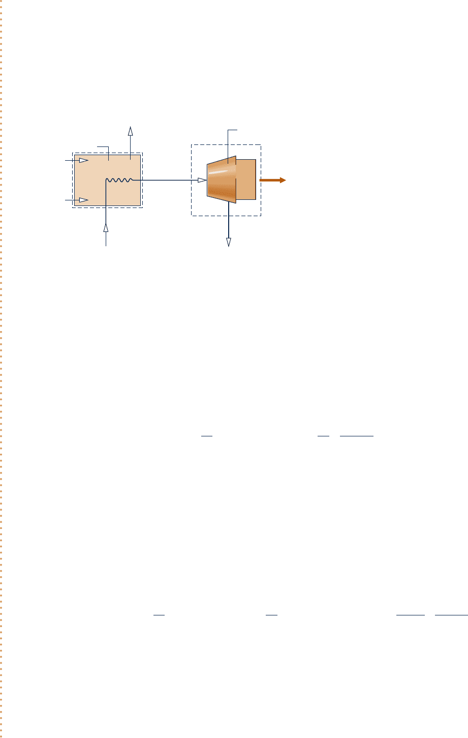
SOLUTION
Known:
Steady-state operating data are known for a cogeneration system that produces both electricity and
low-pressure steam for an industrial process.
Find: For the turbine, determine the power and the rate exergy exits with the steam. Determine the unit costs
of the steam exiting the boiler, the steam exiting the turbine, and the power developed. Also determine the cost
rates of the low-pressure steam and power.
Engineering Model:
1.
Each control volume shown in the accom-
panying figure is at steady state.
2. For each control volume, Q
#
cv
5 0 and the
effects of motion and gravity are negligible.
3. The feedwater and combustion air enter
the boiler with negligible exergy and cost.
4. Expenses related to proper disposal of the
combustion products are included with the
cost of owning and operating the boiler.
5. The unit costs based on exergy of the high-
and low-pressure steam are equal: c
1
5 c
2
.
6. For the environment, T
0
5 298 K.
Process steam 2
W
e
, c
e
·
Turbine-electric
generator
Boiler
Gaseous fuel
Air
Feedwater
Combustion
products
Z
b
= $1080/h
·
Z
t
= $92/h
·
E
f1
p
1
T
1
·
= 35MW
= 50 bar
= 466°C
1
E
fF
·
= 100 MW
p
2
T
2
m
2
= 5 bar
= 205°C
= 26.15 kg/s
·
cents
_____
kW·h
c
F
= 1.44
Fig. E7.10
Schematic and Given Data:
c07ExergyAnalysis.indd Page 401 7/12/10 6:55:35 AM user-s146 c07ExergyAnalysis.indd Page 401 7/12/10 6:55:35 AM user-s146 /Users/user-s146/Desktop/Merry_X-Mas/New/Users/user-s146/Desktop/Merry_X-Mas/New

402 Chapter 7 Exergy Analysis
where E
#
fF
is the exergy rate of the entering fuel, c
F
and c
1
are the unit costs of the fuel and exiting steam,
respectively, and Z
#
b
is the cost rate associated with owning and operating the boiler. Solving for c
1
we get
Eq. 7.32b; then, inserting known values c
1
is determined:
c
1
5 c
F
a
E
#
fF
E
#
f1
b1
Z
#
b
E
#
f1
5 a1.44
cents
kW ? h
ba
100 MW
35 MW
b1 a
1080 $
/
h
35 MW
b`
1 MW
10
3
kW
``
100 cents
1$
`
5 14.11 1 3.092
cents
kW ? h
5 7.2
cents
kW ? h
The cost rate balance for the control volume enclosing the turbine is given by Eq. 7.34a
c
e
W
#
e
1 c
2
E
#
f2
5 c
1
E
#
f1
1 Z
#
t
where c
e
and c
2
are the unit costs of the power and the exiting steam, respectively, and Z
#
t
is the cost rate
associated with owning and operating the turbine. Assigning the same unit cost to the steam entering and
➊ exiting the turbine, c
2
5 c
1
5 7.2 cents/kW ? h, and solving for c
e
c
e
5 c
1
c
E
#
f1
2 E
#
f2
W
#
e
d1
Z
#
t
W
#
e
Inserting known values
c
e
5 a7.2
cents
kW ? h
bc
135 2 20.672 M
W
12.75 MW
d1 a
92$
/
h
12.75 MW
b`
1 MW
10
3
kW
``
100 cents
1$
`
5 18.09 1 0.722
cents
kW ? h
5 8.81
cents
kW ? h
(c) For the low-pressure steam and power, the cost rates are, respectively,
C
#
2
5 c
2
E
#
f2
5 a7.2
cents
kW ? h
b120.67 MW2`
10
3
kW
1 MW
``
$1
100 cents
`
5 $1488
/
h
C
#
e
5 c
e
W
#
e
5 a8.81
cents
kW ? h
b112.75 MW2`
10
3
kW
1 MW
``
$1
100 cents
`
5 $1123
/
h
➊ The purpose of the turbine is to generate power, and thus all costs associated
with owning and operating the turbine are charged to the power generated.
➋ Observe that the unit costs c
1
and c
e
are significantly greater than the unit
cost of the fuel.
➌ Although the unit cost of the steam is less than the unit cost of the power,
the steam cost rate is greater because the associated exergy rate is much
greater.
If the unit cost of the fuel were to double to 2.88 cents/kW ? h,
what would be the change in the unit cost of power, expressed as a per-
cent, keeping all other given data the same? Ans. 153%.
Ability to…
❑
evaluate exergy quantities
required for exergy costing.
❑
apply exergy costing.
✓
Skills Developed
➋
➌
c07ExergyAnalysis.indd Page 402 7/12/10 6:55:39 AM user-s146 c07ExergyAnalysis.indd Page 402 7/12/10 6:55:39 AM user-s146 /Users/user-s146/Desktop/Merry_X-Mas/New/Users/user-s146/Desktop/Merry_X-Mas/New
