Moller K.D. Optics. Learning by Computing, with Examples Using Mathcad, Matlab, Mathematica, and Maple
Подождите немного. Документ загружается.

26 1. GEOMETRICAL OPTICS
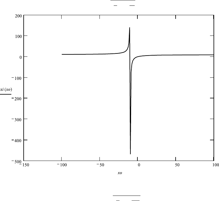
Calculation of Graph for xi as Function of xo over the Total Range of xo
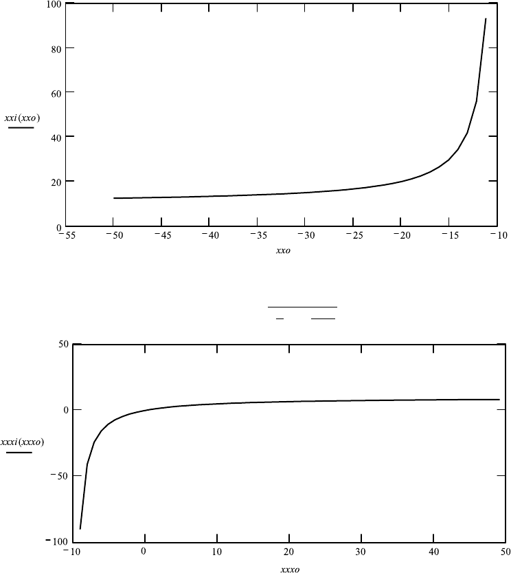
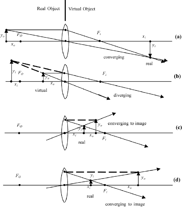
Graph for xi as function of xo over the range of xo to the left of f . Graph for
xi as function of xo over the range of xo to the right of f .
f ≡ 10
Image focus: f Object focus: −f
xo :−100.001, −99.031 ...100
xi(xo):
1
1
f
+
1
xo
.
xxo :−50.001, −49.031 ...− 11
xxi(xxo):
1
1
f
+
1
xxo
.
1.6. THIN LENS EQUATION 27
xxxo :−9.001, −8.031 ...50
xxxi(xxxo):
1
1
f
+
1
xxxo
.
Application 1.10.
1. Observe the singularity at the object focus, which has the same absolute value
as the focal length but with a negative sign. The image focus has a positive
sign. Note that they play different roles in the geometrical construction of the
image.
2. Change the refractive index and describe what happens.
3. Change the focal length and describe what happens.

28 1. GEOMETRICAL OPTICS
FileFig 1.11 (G11TINPOS)
Calculation of image and object foci for f 10. Calculation of image distances
x
i
and magnification for four specific values of object distance x
o
G11TINPOS
Positive Lens
Focal length f is positive, light from left propagating from medium with index 1
to lens of refractive index n. xo on left of lens (negative).
Calculation for Four Positions for Real and Virtual Objects, to the Left and Right of the
Object Focus and Image Focus
Calculation of xi from given xo and focal length. Calculation of magnification.
f ≡ 10 n1: 1 n2:1.5
Image focus: f Object focus: −f
1. xo1:−30
xi1:
1
1
f
+
1
xo1
xi1 15 mm1:
xi1
xo1
mm1 −0.5.
2. xo2:−5
xi2:
1
1
f
+
1
xo2
xi2 −10 mm2:
xi2
xo2
mm2 2.
3. xo3: 5
xi3:
1
1
f
+
1
xo3
xi3 3.333 mm3:
xi3
xo3
mm3 0.667.
4. xo4: 30
xi4:
1
1
f
+
1
xo4
xi4 7.5 mm1:
xi4
xo4
mm4 0.25.
Application 1.11. The distance between the chosen object coordinate and the
resulting image coordinate changes with the choice of the object coordinate.
1. Find analytically the condition for the shortest distance between image and
object.
2. Make a graph of y −x
o
+ x
i
depending on x
o
and find the minimum.
3. Make a sketch.
1.6. THIN LENS EQUATION 29
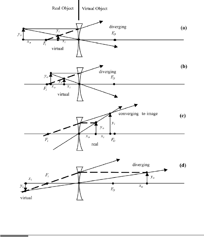
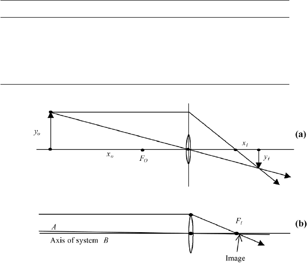
FIGURE 1.11 Geometrical construction of the images for a converging lens with positive f . Real
objects for (a) and (b) and virtual objects for (c) and (d). The light converges to real images in (a),
(c), (d). The light diverges in (b), and a virtual image is obtained by “trace back.”
The geometrical construction of the images for the values calculated in FileFig
1.11 are shown in Figures 1.11a to d.
1. Real object and real image.
The object is presented by an arrow of length y
o
, placed at the object point
x
o
. The image point and the length of the arrow presenting the image can
be geometrically determined. The C-ray is drawn from the top of the object
arrow through the center of the thin lens. The second ray, the PF-ray, is drawn
from the object arrow parallel to the axis to the lens, and from there, through
the image focus. The two rays meet at the position of the image arrow. In
Figure 1.11a, we obtain for a real object a real image.
2. Real object and virtual image.
In Figure 1.11b we place the real object between the object focus and the
lens and draw the C-ray and PF-ray. These rays diverge in a forward direction

30
1. GEOMETRICAL OPTICS
and both are traced back to the left. They meet at the virtual image. A virtual
image is always found when the C-ray and the PF-ray diverge in a forward
direction. If we could place a screen into the position of a virtual image, we
could not see it, because the rays toward the virtual image are diverging.
3. and 4. Virtual object and real images.
In Figures 1.11c and 1.11d we place the object to the right of the lens. We are
considering virtual objects. A virtual object may be produced by the image
formed by another optical imaging system. The virtual objects are placed
between the lens and the image focus and to the right of the image focus. In
both cases we draw the C-ray in a forward direction. The PF-1 ray is drawn
first backward to the lens and then forward through the image focus. The
C-ray and the PF-ray converge to real images for all positions of the virtual
object.
The results of the calculations of the positive thin lens with f −10 are
listed in Table 1.3.
1.6.5 Negative Lens, Graph, Calculations of Image Positions,
and Graphical Constructions of Images
In FileFig 1.12, we show graphs of the thin lens equation, plotting x
i
as a function
of x
o
for negative f . We see the singularity is at the object focus f , which is
now to the right of the lens. To the left of the lens, x
i
is negative. Between the
lens and the object focus, x
i
is positive. To the right of the object focus, x
i
is
negative. As a result, we have three sections. In the first and third sections, for a
negative sign, the image is virtual. In the middle section, for a positive sign, the
image is real.
In FileFig 1.13, we have calculated for four specific values of object distance
the corresponding image distances and the magnification. In Figure 1.12 we have
the geometrical construction of the images for the values calculated in FileFig
1.13.
TABLE 1.3 Positive Lens. f 10, Image Focus 10, Object Focus −10
x
o
x
i
m Image Object
−30 15 −.5r r
−5 −10 2 vi r
5 3.3 .67 r vi
30 7.5 .25 r vi
1.6. THIN LENS EQUATION 31
FIGURE 1.12 Geometrical construction of the images for a diverging lens with negative f . Real
objects for (a) and (b) and virtual objects for (c) and (d). The light converges to real images in (c).
The light diverges in (a), (b), (d), and a virtual image is obtained by “trace back.”
FileFig 1.12 (G12TINNEG)
Graph of image coordinate x
i
, depending on object coordinate x
o
for the thin
lens equation with f −10.
G12TINNEG is only on the CD.
Application 1.12.
1. Observe the singularity at object focus, which has the same absolute value
as the focal length but with a positive sign. The image focus has a negative
sign. Note that they play different roles in the geometrical construction of the
image.
2. Change the refractive index and describe what happens.
3. Change the focal length and describe what happens.

32 1. GEOMETRICAL OPTICS
FileFig 1.13 (G13TINNEG)
Calculation of image focus and object focus for negative lens. Calculation of
image distances x
i
and magnification for four specific values of object distance
x
o
.
G13TINNEG is only on the CD.
Application 1.13. The distance between the chosen object coordinate and
resulting image coordinate changes with the choice of the object coordinate.
1. Modify the analytical calculation done in Application FF11 for the condition
of the shortest distance between image and object.
2. Make a sketch.
The geometrical construction of the images for the values calculated in FileFig
1.13 are shown in Figures 1.12a to d.
1. and 2. Real object to the left of the lens and virtual image.
The object is presented by an arrow of length y
o
, placed at the object point x
o
to the left of the negative lens. The image point and the length of the arrow
presenting the image can be geometrically determined using the C-ray and
the PF-ray. The C-ray is drawn from the top of the object arrow through the
center of the thin lens. The PF-ray is drawn from the object arrow parallel to
the axis to the lens, and then diverges in a forward direction. It is traced back
to the image focus. The two rays meet at the positions of the image arrow. In
Figures 1.12a and 1.12b, we obtain for a real object a virtual image. A virtual
image is obtained when the C-ray and the PF-ray diverge in a “forward”
direction.
3. Virtual object between lens and object focus.
In Figure 1.12c, we place the virtual object between the object focus and
the lens and draw the C-ray. The PF-ray is first traced back to the lens, then
connected to the image focus, and extended in the forward direction. The two
rays meet in the forward direction at a real image.
4. Virtual object on the right side of the object focus.
In Figure 1.12d, we place the virtual object to the right of the object focus
and draw the C-ray. The PF-ray is first traced back to the lens, then connected
to the image focus and extended further in the backward direction. The two
rays meet in the backward direction for a virtual image.
The results of the calculations of the negative thin lens with f −10 are
listed in Table 1.4
For the geometrical construction, we note that the size of the lens does not
matter. One uses a plane in the middle of the lens with sufficient extension in the
y direction; see Figure 1.13a.
1.6. THIN LENS EQUATION 33
TABLE 1.4 Negative Lens. f −10, Image Focus −10, Object focus 10
x
o
x
i
m Image Object
−30 −7.5 .25 vi r
−5 −3.3 .67 r r
5 10 2 vi vi
30 −15 −.5vi vi
FIGURE 1.13 (a) Image formation of an object larger than the diameter of the lens. The extended
plane of the lens is used; (b) image formation for an object at infinity. The axis B of the system is
the ray from the center of the object through the center of the lens. the PF-ray is assumed to come
from the top of an object at finite distance; the corresponding image is indicated.
If the object is at infinity, one uses for the object distance a finite number so
that the image is not exactly at the focal point, where it would have a length
equal to zero (Figure 1.13b).
1.6.6 Thin Lens and Two Different Media on the Outside
We go back to the thin lens equation and choose different indices of refraction
at the two media on both sides of the lens. We start again from the definitions
ζ
o
x
o
/n
1
, ζ
i
x
i
/n
3
, ρ
1
r
1
/(n
2
− n
1
) and ρ
2
r
2
/(n
3
− n
2
) and have
−n
1
/x
0
+ n
3
/x
i
(n
2
− n
1
)/r
1
+ (n
3
− n
2
)/r
2
. (1.53)
We call the focal length of the thin lens f
n
given by
1/f
n
(n
2
− n
1
)/r
1
+ (n
3
− n
2
)/r
2
(1.54)
and obtain the thin lens equation
−n
1
/x
o
+ n
3
/x
i
1/f
n
. (1.55)

34 1. GEOMETRICAL OPTICS
This equation is very similar to the spherical surface imaging equation discussed
in Section 1.4a just as we found there, we have different values for the object
focus and image focus.
For the object focus, when the image point is assumed to be at positive infinity,
we have
x
of
−n
1
f
n
(1.56)
and for the image focus, obtained when the object point is assumed to be at
negative infinity, we have
x
if
n
3
f
n
. (1.57)
The construction of the images for positive and negative lenses is similar to the
procedure for the spherical surfaces and is not discussed further. The value of
the focal length for different cases of the refractive indices may be calculated
using FileFig 1.14.
FileFig 1.14 (G14TINFOC)
Calculation of the focal length and object and image focus of the thin lens for
different combinations of the refractive indices.
G14TINFOC
Focal Length
1. Calculation of focal length of thin lens of refractive index n2 in medium with
refractive index n1.
First surface: r1:−5. Second surface: r2: 5. r is positive for convex
surface, negative for concave surface. Refractive index of lens n2: n2: 1.
and Refractive index of medium n1: n1: 1.5.
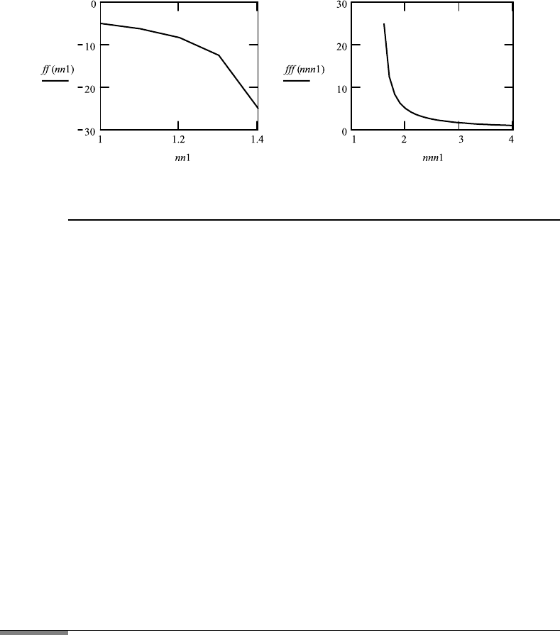
2. Graph of focal length of thin lens with index n2 depending on refractive index
of medium n1.
The range on n1 is divided into lower and higher ranges because of sin-
gularity. Refractive index of lens nn2: nn2: 1.5. Lower range: nn1:
1, 1.1 ...nn2 −.00001. Upper range: nnn1: nn2 + .1,nn2 + .2 ...4.
ff (nn1) :
1
nn2−nn1
r1
+
nn1−nn2
r2
fff (nnn1) :
1
nn2−nnn1
r1
+
nnn1−nn2
r2
.
1.7. OPTICAL INSTRUMENTS 35
Application 1.14. Consider the case n
2
>n
1
. What is the result when
interchanging n
1
and n
2
?
Applications for the Sections on Positive and Negative
Lenses
1. Air lens in plastic. A plastic rod is flat on one side and has a spherical surface
on the other side. The spherical surface is concave with respect to the incident
light, which comes from the flat side. An identical second rod is taken and
the two curved ends are put together, forming an air lens by the ends of the
two rods. The cross-section of this lens has its thinnest point in the middle.
Assume that the radii of curvatures of the spherical surfaces are r −r
10
cm and the refractive index of the rod is n 1.5. Sunlight is incident on an
object on the face of the first rod at 20 cm from the air lens. Find the image
distance.
2. Thin lens on water. A lens of refractive index n 1.5 is put on water, one
surface in air, the other in water. The lens is a symmetric biconvex lens and has
a focal length of f 10 cm in air. The refractive index of water is n 1.33.
a. Calculate the radii of curvature of the lens in air and the focal length to be
used in the above position.
b. Sunlight is shining on the lens; calculate the image distance in the water.
1.7 OPTICAL INSTRUMENTS
Optical instruments, such as magnifiers, and microscopes, enlarge tiny objects,
making it possible to observe objects we can barely see with the naked eye. The
magnifier gives us a modest magnification, in most cases less than ten times. The
microscope makes it possible to observe objects of about 1 micron diameter, and
the telescope enables us to see objects at a far distance in more detail. Our eye is
a one lens system and may produce a real image of a real object, like a positive
lens (Figure 1.11a). The real image of a real erect object of a positive lens is