Moeller. Wiring manual. Automation and Power distribution
Подождите немного. Документ загружается.

All about Motors
Three-phase automatic stator starters
Moeller Wiring Manual 02/05
8-91
8
Method of operation
Pushbutton I energizes step contactor Q16 and
timing relay K1. Q16/14–13 – maintain
themselves via Q11, Q11/32–31 and
pushbutton 0. The motor is connected to the
supply with rotor resistors R1 + R2. When the
set starting time has elapsed, normally open
contact K1/15–18 energizes Q17. Step
contactor Q17 bypasses starting stage R1. At
the same time, normally open contact
Q17/14–13 energizes K2. When the set
starting time has elapsed, K2/15–18 energizes
mains contactor Q11, which bypasses the
second starting stage R2, and the motor runs
at rated speed. Q11 maintains itself via
Q11/14–13. Q16, Q17, K1 and K2 are
de-energized by normally closed contacts
Q11/22–21 and Q11/32–31. The motor is
switched off either after actuation of
pushbutton 0, or in the event of an overload,
by normally closed contact 95–96 of the
overload relay F2 or normally open contact
13–14 of the motor-protective circuit-breaker
or circuit-breaker.
Step contactor Q17, resistor R2 and timing
relay K1 are omitted in single-stage starting
circuits. Timing relay K2 is connected directly
to Q16/13 and resistor R2 is connected by
means of its terminals U1, V1 and W1 to
Q11/2, 4, 6.
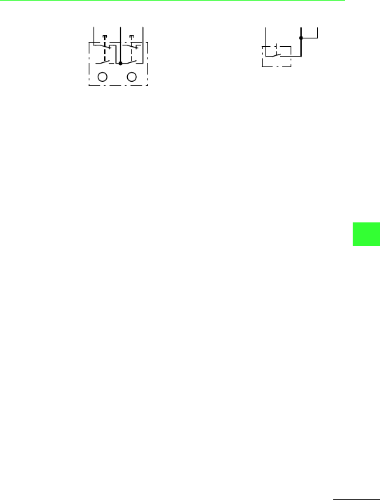
Three-wire
control
Two-way
pushbutton
I = ON
0 = OFF
Two-wire
control
-S11
Q11
32
22
21
Q11
21
F2
96
22
21
14
13
14
13
0
I
A
B
F2
96
Q11
22
Q11
32
-S12
All about Motors
Three-phase automatic stator starters
Moeller Wiring Manual 02/05
8-92
8
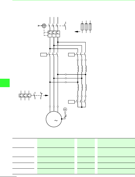
Three-phase automatic stator resistance starter ATAINL with mains contactor and
starting transformer, 1-stage, 3-phase
Use F2 when using F1 instead of Q1. Rating of switchgear
L1
L2 L3
4
1
5
3
2
4
6
UV
W
1
5
3
2
4
6
a
U2
V2
W2
1U1
2W1
2V1
2U1
1V1
1W1
M
3
M1
F1
2
6
1
5
3
Q1
13
14
Q11
1
5
3
2
4
6
K1
Q13
2
4
6
97
95
98
96
I > I > I >
Starting voltage = 0.7 x U
e
(typical value) Tightening
torque
= 0.49 x motor full-load
current
Starting current = 0.49 x motor full-load
current
Q1, Q11 = I
e
I
A
/I
e
= 6 Q16 = 0.6 x I
e
t
A
= 10 s Q13 = 0.25 x I
e
S/h = 30
All about Motors
Three-phase automatic stator starters
Moeller Wiring Manual 02/05
8-93
8
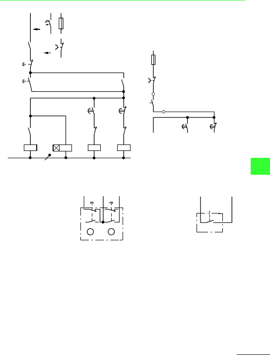
Method of operation
Actuation of pushbutton I simultaneously
energizes star contactor Q13, timing relay K1
and, via normally open contact Q13/13–14,
step contactor K16, and are maintained via
K1/13–14. When K1 has elapsed, normally
closed contact K1/55–56 de-energizes star
contactor Q13 and – via normally open
contact Q13/13–14 – Q16 de-energizes: The
starting transformer is disconnected, and the
motor runs at rated speed.
The motor cannot start up again unless
previously switched off by actuation of
pushbutton 0, or in the event of an overload,
by normally closed contact 95–96 of the
overload relay F2. With two-wire control,
overload relay F2 must always be set to
manual reset. If the motor has been switched
off by F2, the motor cannot start up again
unless the manual reset is released.
Two-wire control
Always set overload relay to manual reset
(automatic reset)
Q16: Step contactor
K1: Timing relay
Q11: Mains contactor
Q13: Star contactor
Three-wire control
I: ON
0: OFF
Two-wire
control
L1
Q1
F0
13
14
95
96
F2
21
S11
0
I
13
14
K1
13
14
13
14
Q13
Q16
N
A1
A2
K1
Q13
A1
A2
Q11
K1
A1
A2
K1
Q11
Q13
22
21
A1
A2
22
21
67
68
55
56
22
L1
(Q11/1)
-F0
95
96
-F2
-S12
-K1
-K1
55
96
67
68
-S11
K1
13
22
21
F2
96
22
21
14
13
14
13
0
I
A
B
K1
14
-S12
F2
96
K1
55
Moeller Wiring Manual 02/05
8-94
All about Motors
8
Three-phase automatic rotor starters
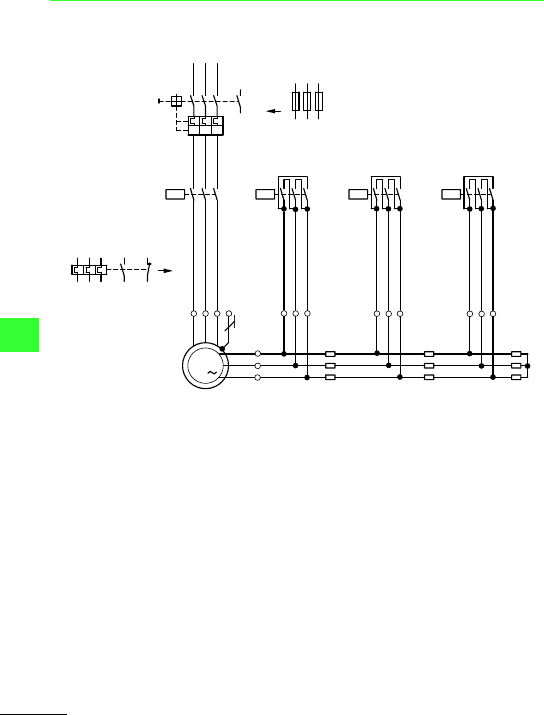
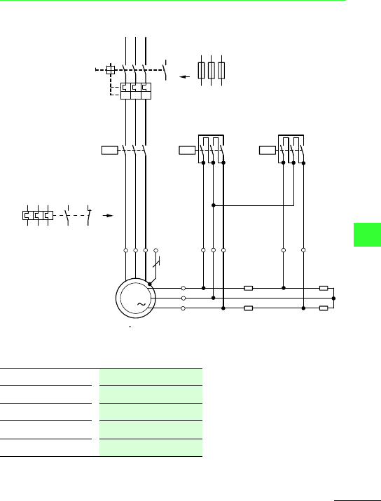
Three-phase automatic rotor resistance starters DAINL
3-stage, rotor 3-phase
Use F2 when using F1 instead of Q1.
L1
L2 L3
-Q1
1
3
5
I >
I >
I >
13
14
-F1
2
6
4
2
4
6
PE
U
V
W
M
3
-M1
-Q12
2
4
6
97
95
98
96
1
3
5
-Q11
-F2
2
4
6
1
3
5
1
5
3
2
4
6
-Q13
-Q14
2
4
6
1
3
5
K
L
M
U3
V3
W3
U2
V2
W2
-R3 -R2
U1
V1
W2
-R1
All about Motors
Three-phase automatic rotor starters
Moeller Wiring Manual 02/05
8-95
8
2-stage, rotor 2-phase
Use F2 when using F1 instead of Q1.
Rating of switchgear
L1
L2 L3
1
3
5
13
14
I>
I>
I>
2
6
4
1
3
5
2
4
6
PE
U
V
W
M
3
-M1
-Q11
1
3
5
-F2
2
4
6
-R2
U1
V1
-R1
-Q1
-F1
97
95
98
96
K
L
M
-Q12
-Q14
2
4
6
1
3
5
U2
XY
V2
2
4
6
Starting current = 0.5–2.5 x I
e
Starting torque = 0.5 to pull-out torque
Q1, Q11
= I
e
Step contactors = 0.35 x I
rotor
Final step contactors = 0.58 x I
rotor
All about Motors
Three-phase automatic rotor starters
Moeller Wiring Manual 02/05
8-96
8
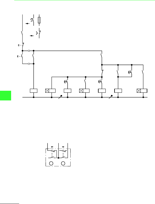
With mains contactor, style 3-stage, rotor 3-phase
Q11: Mains contactor
K1: Timing relay
Q14: Step contactor
K2: Timing relay
Q12: Step contactor
Q13: Final step contactor
K3: Timing relay
Q1
F2
L1
N
F0
0
S11
I
Q11
A1
A2
A1
A2
K1
K2
Q14
A1
A2
13
14
13
14
95
96
21
22
13
14
Q11
13
14
K1
Q14
A1
A2
15
18
K2
Q12
14
13
A1
A2
15
18
A1
A2
Q13
Q13
Q13
32
31
14
13
U3
A1
A2
U3
15
18
Q12
Q11
44
43
Two-way push-
button
I: ON
0: OFF
For connection of further control circuit
devices: a section “Control circuit devices
for star-delta starting”, page 8-49
F2
96
Q11
14
Q11
13
0
I
-S11
21
22
21
22
13
14
13
14
A
B

All about Motors
Three-phase automatic rotor starters
Moeller Wiring Manual 02/05
8-97
8
Method of operation
Pushbutton I energizes mains contactor Q11:
normally open contact Q11/14–13 transfers
the voltage, Q11/44–43 energizes timing relay
K1. The motor is connected to the supply with
rotor resistors R1 + R2 + R3 in series. When
the set starting time has elapsed, normally
open contact K1/15–18 energizes Q14. Step
contactor Q14 short-circuits starting stage R1
and via Q14/14–13 energizes timing relay K2.
When the set starting time has elapsed,
K2/15–18 energizes step contactor Q12,
which short-circuits starting stage R2 and via
Q12/14–13 energizes timing relay K3. When
the set starting time has elapsed, K3/15–18
energizes final step contactor Q13, which is
maintained via Q13/14–13. Step contactors
Q14 and Q13 as well as timing relays K1, K2
and K3 are de-energized via Q13. Final step
contactor Q13 short-circuits the rotor slip
rings: the motor operates with rated speed.
The motor is switched off either by pushbutton
0, or in the event of an overload, by normally
closed contact 95–96 of the overload relay F2
or normally open contact 13–14 of the
motor-protective circuit-breaker or
circuit-breaker.
Step contactors Q13 and/or Q12 with their
resistors R3, R2 and timing relays K3, K2 are
omitted in single-stage or two-stage starting
circuits. The rotor is then connected to the
resistance terminals U, V, W2 or U, V, W1. The
references for step contactors and timing
relays in the wiring diagrams are then changed
from Q13, Q12, to Q12, Q11 or to Q13, Q11 as
appropriate.
When there are more than three stages, the
additional step contactors, timing relays and
resistors have appropriate increasing
designations.
Moeller Wiring Manual 02/05
8-98
All about Motors
8
Switching of capacitors
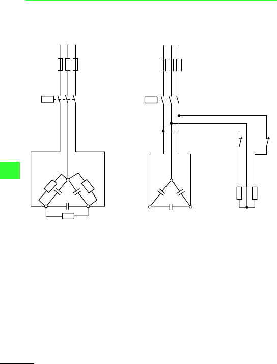
Contactors for capacitors DIL
Individual circuit without
quick-discharge resistors
Individual circuit with quick-discharge resistors
R1 discharge resistors fitted in
capacitor
R1 discharge resistors fitted to contactor
L3
-F1
1
3
5
2
4
6
-Q11
-R1
-C1
-R1
-R1
L1
L2
L3
-F1
1
3
5
2
4
6
-Q11
-R1
-C1
-R1
L1
L2
21
22
-Q11
-Q11
31
32
All about Motors
Switching of capacitors
Moeller Wiring Manual 02/05
8-99
8
Two-way pushbutton
For connection of further control circuit
devices: a section “Control circuit devices
for star-delta starting”, page 8-49
L1
(Q11/1)
-F0
21
22
-S11
0
I
13
14
13
14
-Q11
-Q11
A1
A2
N
22
L1
21
0I
Q11
14
A
B
Q11
13
14
13
22
21
14
13
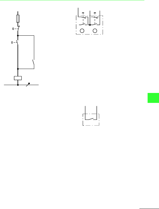
Two-wire control
In the case of actuation by means of power
factor correction relay, check that this has
sufficient power to actuate the contactor coil.
Interpose a contactor relay if necessary.
Method of operation
Pushbutton I energizes contactor Q11. Q11
energizes and maintains itself via its own
auxiliary contact 14–13 and pushbutton 0.
Capacitor C1 is now energized. Discharge
resistors R1 are not operative when contactor
Q11 is energized. Actuation of pushbutton 0
effects de-energization. Normally closed
contacts Q11/21–22 then switch discharge
resistors R1 to capacitor C1.
L1
-S12
Q11
A1
All about Motors
Switching of capacitors
Moeller Wiring Manual 02/05
8-100
8
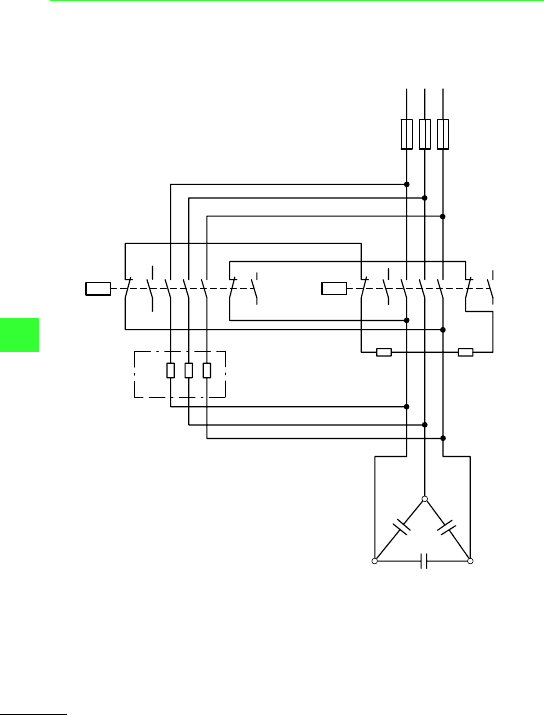
Capacitor contactor combination
Capacitor contactor with pilot contactor and
series resistors. Individual and parallel circuit
with and without discharge resistors and with
series resistors.
On the version without discharge resistors,
resistors R1 and the connections to the
auxiliary contacts 21–22 and 31–32 are
omitted.
L3
L1
L2
-F1
1
3
5
2
4
6
-Q14
-R1
-C1
-R1
21
22
-Q11
31
32
43
44
13
14
21
22
A1
A2
31
32
43
44
1
3
5
2
4
6
A1
A2
13
14
-R2
