Moeller. Wiring manual. Automation and Power distribution
Подождите немного. Документ загружается.

All about Motors
Switching of capacitors
Moeller Wiring Manual 02/05
8-101
8
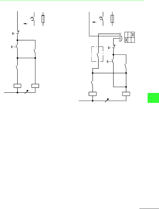
Method of operation
Actuation by two-way pushbutton S11:
Pushbutton I energizes pilot contactor Q14.
Q14 switches capacitor C1 in with bridged
series resistors R2. Normally open contact
Q14/14–13 energizes mains contactor Q11.
Capacitor C1 is then switched in with bridged
series resistors R2. Q14 is maintained via
Q11/14–13 when Q11 has closed.
Discharge resistors R1 are not operative when
Q11 and Q14 are energized. Pushbutton 0
effects de-energization. Normally closed
contacts Q11/21–22 and 31–32 then switch
discharge resistors R1 to capacitor C1.
Q11: Mains contactor
Q14: Pilot contactor
Actuation by two-way pushbutton S11 Actuation by selector switch S13, two-wire
control S12 (power factor correction relay)
and two-way pushbutton S11
-F0
0
I
-S11
L1
(Q11/1)
-Q14
21
22
-Q11
A1
A2
13
14
-Q11
13
14
13
14
-Q14
A1
A2
N
-F0
0
I
-S12
L1
(Q11/1)
-Q14
21
22
13
14
-Q11
13
14
13
14
A1
A2
-S12
-Q14
A1
A2
-Q11
N
T0 (3)-1-15431
1
2
3
4
1
0
2
Moeller Wiring Manual 02/05
8-102
All about Motors
8
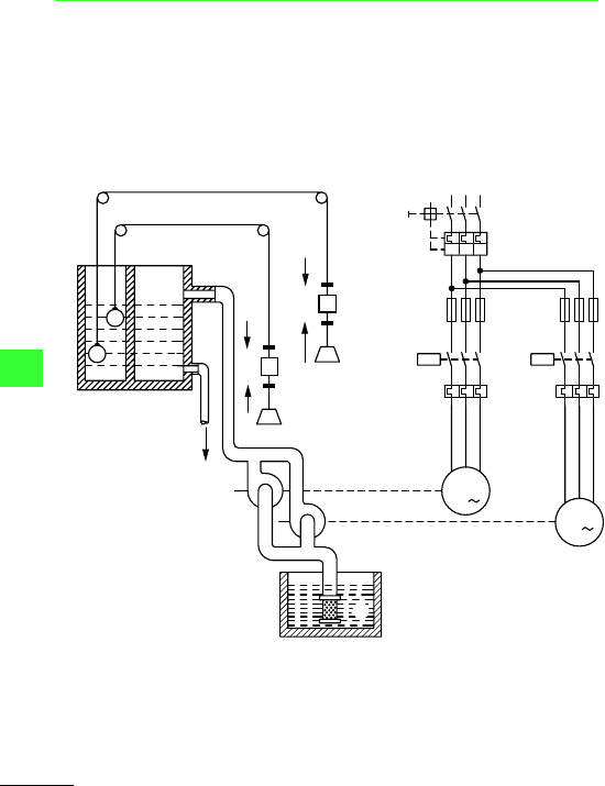
Duplex pump control
Fully automatic control for two pumps
Starting sequence of pumps 1 and 2 can be
selected by control switch S12
Control circuit wiring with two float switches
for basic and peak loads (operation is also
possible with two pressure switches)
P1 Auto
=
Pump 1 constant load,
Pump 2 peak load
P2 Auto
=
Pump 2 constant load,
Pump 1 peak load
P1 + P2
=
Direct operation independent of
float switches (or pressure
switches)
a Cable with float, counterweight, pulleys
and clamps
b Storage tank
c Inlet
d Pressure pipe
e Outlet
f Centrifugal or reciprocating pump
g Pump 1
h Pump 2
i Suction pipe with filter
j Well
L1
L2 L3
-Q1
-F22
-Q11
U
V
W
M
3
-M1
-M2 M
3
F7
-F11
-F21
-F12
-Q12
U
V
W
F8
b
d
F7
Q
Q
a
a
F8
c
e
f
f
i
h
g
0
0
I
I
F7: 0
F7: I
F8: 0
F8: I
j
I > I > I >
All about Motors
Duplex pump control
Moeller Wiring Manual 02/05
8-103
8
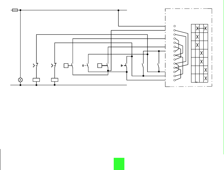
Float switch F7 closes before F8 Q11: Pump 1 mains contactor Q12: Pump 2 mains contactor
Method of operation
The duplex pump control is designed for operation of
two pump motors M1 and M2. Control is via float
switches F7 and F8.
Operating mode selector switch S12 in position P1
auto: The system operates as follows:
When the water level in the storage tank falls or
rises, F7 switches pump 1 on or off (basic load). If the
water level drops below
the range of F7 (discharge is greater than
intake), F8 starts pump 2 (peak load). When
the water level rises again, F8 is deactivated.
Pump 2 continues running until F7 stops both
pumps.
The operating sequence of pumps 1 and 2 can
be determined using operating mode selector
switch S12: Position P1 auto or P2 auto.
In position P1 + P2, both pumps are in operation,
independent of the float switches (Caution! Tank
may possibly overflow).
On the version of duplex pump control with auto-
matic load sharing (T0(3)-4-15915), S12 has a fur-
ther position: the sequence of operations is auto-
matically reversed after each cycle.
F11
F0
-F12
-F22
95
96
95
96
-F7
Q
2
1
-S11
14
13
-F8
Q
-S21
2
1
14
13
-Q12
14
13
-Q11
14
13
N
EO -Q11
A1
A2
-Q12
A1
A2
-S12
L
1
2
3
4
5
6
7
8
9
10
11
12
13
0
P 1
P 2
P 1, P 2
Auto
Auto
T0(3)-4-15833
Moeller Wiring Manual 02/05
8-104
All about Motors
8
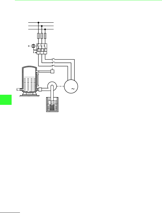
Fully automatic pump control
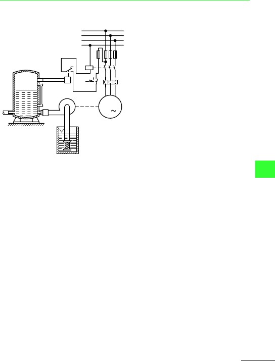
With pressure switch for air tank and domestic
water supply without water failure (run dry)
safety device
With 3-pole pressure switch MCSN (main
circuit)
F1: Fuses (if required)
Q1: Motor-protective switch, manual
(z.B.PKZ)
F7: Pressure switch MCSN, 3-pole
M1: Pump motor
a Air or pressure tank
b Non-return valve
c Pressure pipe
d Centrifugal (or reciprocating) pump
e Suction pipe with filter
f Well
L1
L2
L3
-F1
-Q1
a
b
d
c
e
f
U
VW
-M1
M
3
P
-F7
I > I >I >
All about Motors
Fully automatic pump control
Moeller Wiring Manual 02/05
8-105
8
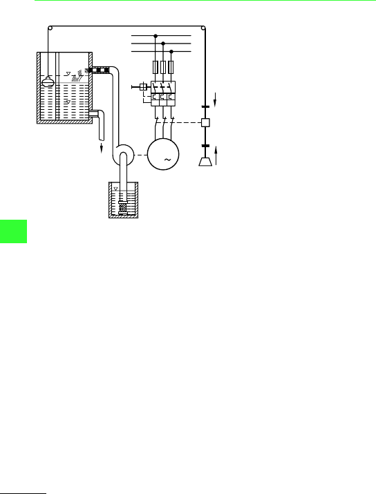
With single-pole pressure switch MCS (control
circuit)
F1: Fuses
Q11: Contactor or automatic star-delta
starter
F2: Overload relay with automatic reset
F7: Pressure switch MCS, 1-pole
M1: Pump motor
a Air or pressure tank
b Non-return valve
c Centrifugal (or reciprocating) pump
d Pressure pipe
e Suction pipe with filter
f Well
3
5
24
6
95
96
-M1
M
3
U
VW
L1
L2
L3
-F1
-F2
a
b
c
d
e
f
P
N
-Q11
1
-F7
All about Motors
Fully automatic pump control
Moeller Wiring Manual 02/05
8-106
8
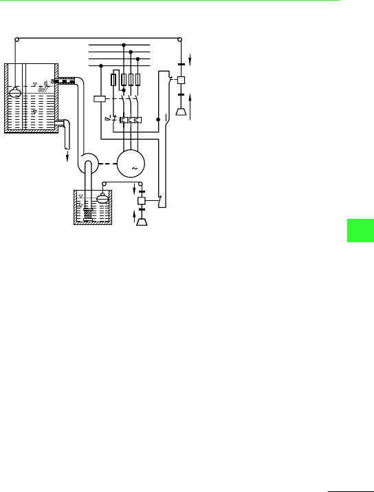
With 3-pole float switch SW (main circuit)
F1: Fuses (if required)
Q1: Motor-protective switch, manual
(z.B.PKZ)
F7: Float switch 3-pole (circuit: pump
full)
M1: Pump motor
HW: Highest level
NW: Lowest value
a Cable with float, counterweight,
pulleys and clamps
b Storage tank
c Pressure pipe
d Centrifugal (or reciprocating) pump
e Outlet
f Suction pipe with filter
g Well
U
VW
L1
L2
L3
-F1
-F7
I
0
HW
NW
-Q1
-M1
Q
M
3
a
c
b
d
e
f
g
I > I >I >
All about Motors
Fully automatic pump control
Moeller Wiring Manual 02/05
8-107
8
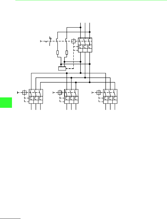
With single-pole float switch SW (control
circuit)
F1: Fuses
Q11: Contactor or automatic
star-delta starter
F2: Overload relay with automatic
reset
F8: Float switch 1-pole (circuit:
pump full)
S1: Changeover switch
MANUAL-OFF-AUTO
F9: Float switch 1-pole (circuit:
pump full)
M1: Pump motor
a Cable with float, counterweight,
pulleys and clamps
b Storage tank
c Pressure pipe
d Centrifugal (or reciprocating)
pump
e Outlet
f Suction pipe with filter
g Water-failure monitoring by
means of a float switch
h Well
L1
U
VW
L2
L3
N
-F1
-F2
-Q11
13
5
24
6
95
96
-F8
0
H
A
-M1
S1
HW
NW
M
3
-F9
I
0
Q
Q
a
b
c
d
e
h
f
g
0
I
Moeller Wiring Manual 02/05
8-108
All about Motors
8
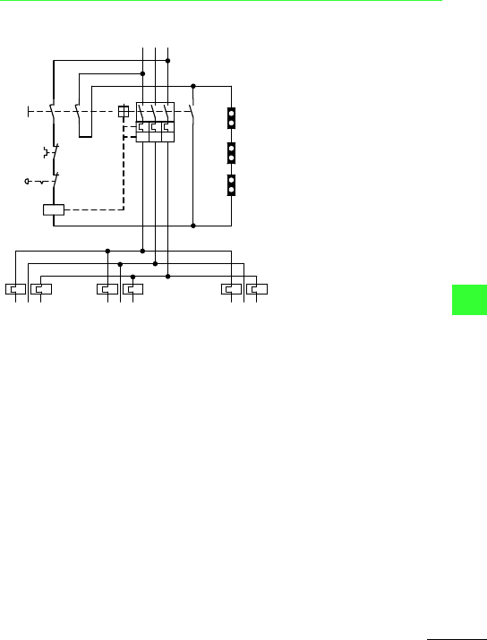
Off position interlock of the loads
Solution using NZM circuit-breakers
Off position interlock for control switches
(Hamburg circuit) with auxiliary contact VHI
(S3) and undervoltage release. Cannot be used
with motor operator.
-S3
-R1
-R2
51
52
U <
-Q1
I >
I >
I >
I >
I >
I >
-Q2
I >
I >
I >
-Q3
I >
I >
I >
-Q4
Moeller Wiring Manual 02/05
8-109
All about Motors
8
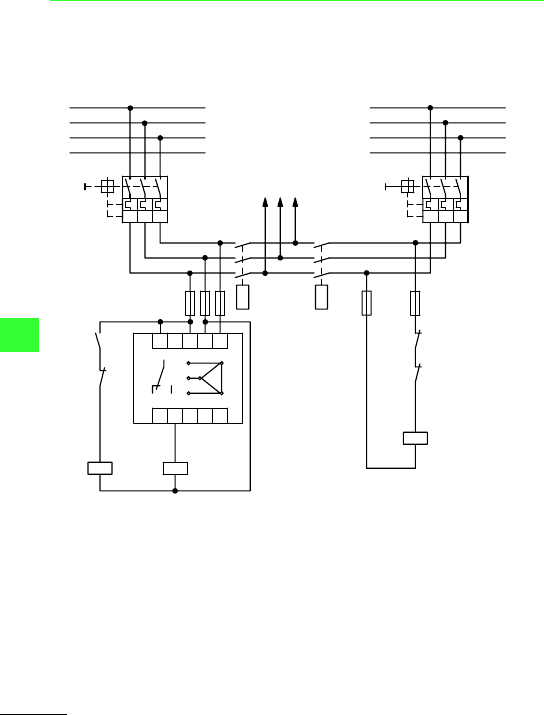
Fully automatic main transfer switch with automatic reset
Off position interlock for control or master
switches by means of auxiliary contacts VHI
(S3), NHI (S1) and undervoltage release.
Cannot be used with motor operator.
a Emergency-Stop
b Off position interlock
contacts on the control or
master switches
-S3
a
V
95
96
U <
-Q1
-S1
51
52
10
11
10
11
10
11
b
b
b
I > I > I >
All about Motors
Fully automatic main transfer switch with automatic reset
Moeller Wiring Manual 02/05
8-110
8
Changeover device to DIN VDE 0108 – Power systems and safety power supply in
buildings for public gatherings:
Automatic resetting, the phase-monitor is set
to:
Pick-up voltage U
on
= 0.95 x U
n
Drop-out voltage U
b
= 0.85 x U
on
Method of operation
Main switch Q1 is closed first, followed by
main switch Q1.1 (auxiliary supply).
Phase monitor K1 is energized via the main
supply and immediately energizes contactor
relay K2. Normally closed contact K2/21–22
blocks the circuit of Contactor Q12 (auxiliary
supply) and normally open contact K2/13–14
closes the circuit of contactor Q11. Contactor
Q11 energizes and switches the mains supply
on the loads. Contactor Q12 is also interlocked
against main supply contactor Q11 via
normally closed contact Q11/22–21.
a Main supply
b Auxiliary supply
c To load
L1
L2
L3
N
-Q1
-F01
21
22
14
21
21
22
22
11
11
12
14
12
14
R
R
S
S
T
T
-F02
5
6
3
4
1
2
5
6
3
4
1
2
-Q1.1
-Q11
-K2
-Q12
-Q12
-Q11
-K2
-Q12
-Q11 -K2
-K1
A1
A2
A1
A2
A1
A2
L2.1
L3.1
N
L1.1
13
ab
c
I > I > I >
I > I > I >
