Middleton W.M. (ed.) Reference Data for Engineers: Radio, Electronics, Computer and Communications
Подождите немного. Документ загружается.

40-18
Activity
REFERENCE
DATA
FOR ENGINEERS
All Noise Continuous
Sources Interior Sources*
Leq
(dB)
L,
(dB)**
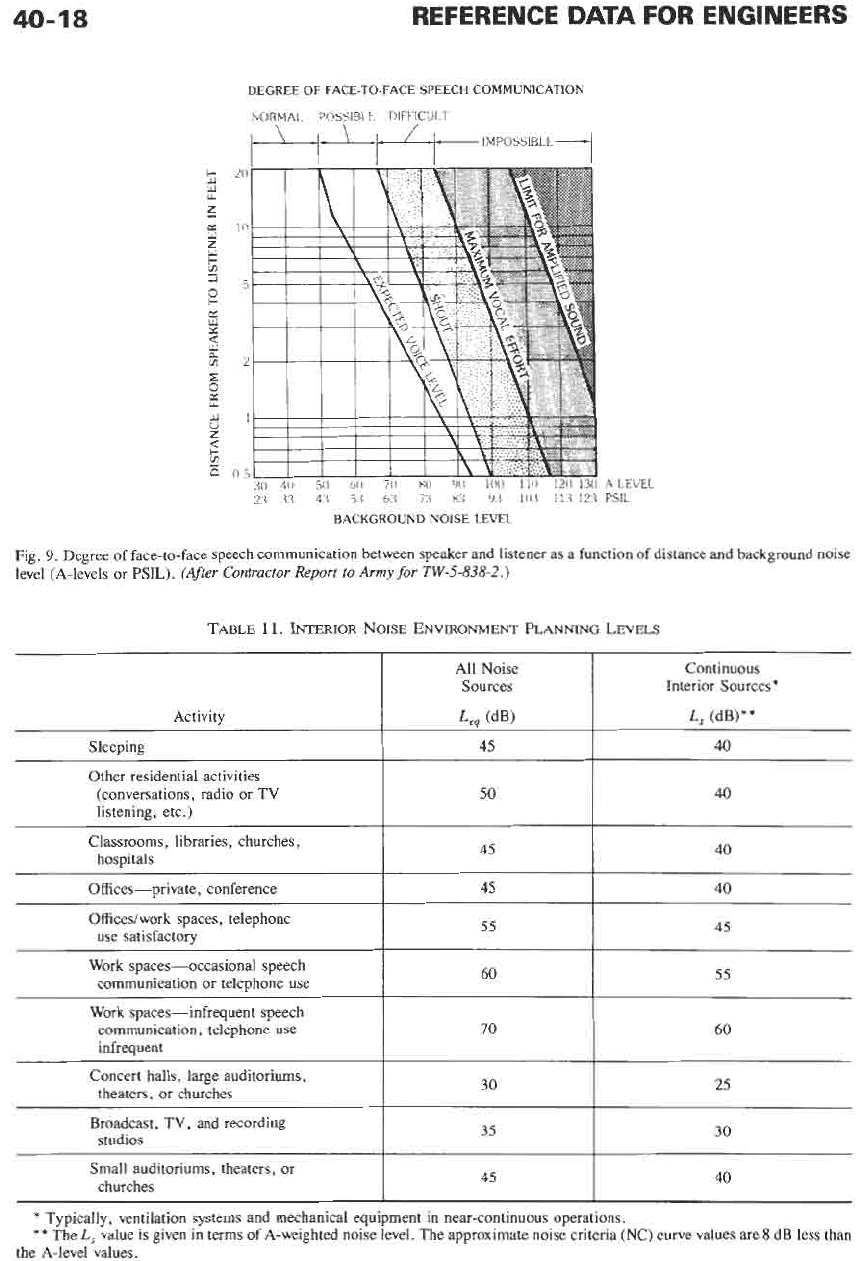
DEGREE
OF FACE-TO-FACE SPEECH COMMUNICATION
NORMAL.
P0SSlBl.t
DIFFICUIKT
Sleeping
Other residential activities
(conversations, radio
or
TV
listening, etc.)
Classrooms, libraries, churches,
hospitals
A~LE
PSIL
45
40
50 40
45 40
VEL
Offices-private, conference
Offices/work spaces, telephone
use
satisfactory
Fig.
9.
Degree of face-to-face speech communication between speaker and listener as a function of distance and background noise
level (A-levels or PSIL).
(After
Contractor Report
to
Army
for
TW-5-838-2.)
45 40
55 45
Work spaces-occasional speech
communication or telephone
use
60
55
Work spaces-infrequent speech
communication, telephone use
infrequent
70
60
Concert halls, large auditoriums,
theaters, or churches
30
25
Broadcast, TV, and recording
studios
35
30
Small auditoriums, theaters, or
churches
45
40
I I
*
Typically, ventilation systems and mechanical equipment in near-continuous operations.
**
The
L,
value is given in terms of A-weighted noise level. The approximate noise criteria
(NC)
curve values are 8 dB less than
the A-level values.
ELECTROACOUSTICS
ambient level in the source room and hence the energy
striking the party* surface, and by increasing the
transmission loss of the party surface. Sound travels
from sources into receiving rooms directly through
building elements such as walls, windows, or doors or
indirectly through “sound leaks” such as cracks,
HVAC, plumbing, electrical facilities, plenums above
suspended ceilings, corridors, etc.
Sound isolation should be contrasted with absorp-
tion. Efficient sound absorbers such as glass fiber or
open-cell polyurethane foam do not contain
or
isolate
sound. Efficient sound isolators or containers such as
heavy walls do not absorb sound.
In
the United States, the sound isolating value of
walls and other elements is frequently specified in terms
of STC (see ASTM E413-87). More recently, it is also
specified in terms of
ALA,
the A-weighted sound
reduction between typically furnished small rooms (see
ASTM E597-87). Where usable,
ALA
has the advan-
tage of easier field measurement than STC.
Walls
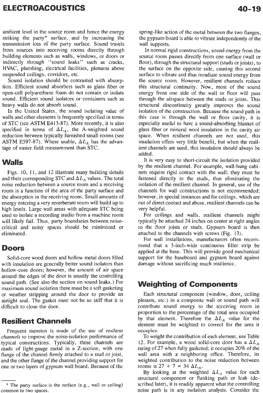
Figs.
10,
11,
and 12 illustrate many building details
and their corresponding STC and
ALA
values. The total
noise reduction between a source room and a receiving
room is a function of the area of the party surface and
the absorption in the receiving room. Small amounts of
energy entering a very reverberant room will build up to
high levels. Large wall areas with adequate STC being
used to isolate a recording studio from a machine room
will likely fail. Thus, party boundaries between noise-
critical and noisy spaces should be minimized or
eliminated.
Doors
Solid-core wood doors and hollow metal doors filled
with insulation are generally better sound isolators than
hollow-core doors; however, the amount of
air
space
around the edges of the door is usually the controlling
sound path. (See also the section on sound leaks.) For
maximum sound isolation there must be a soft gasketing
or weather stripping around the door to provide an
airtight seal. The gasket must not be
so
stiff that it is
difficult to close the door.
Resilient Channels
Frequent mention
is
made
of the use of
resilient
channels
to improve the noise-isolation performance of
typical constructions. Typically, these channels are
made of light-gauge metal in a Z-section, with one
flange
of
the channel firmly attached to a stud or joist,
and the other flange of the channel providing support for
one or two layers of gypsum wall board. Because of the
*
The
party
surface
is
the
surface (e.g.,
wall
or
ceiling)
common
to
two
spaces.
spring-like action of the metal between the two flanges,
the gypsum board is able to vibrate independently of the
wall supports.
In normal rigid constructions, sound energy from the
source room passes directly from one surface (wall or
floor), through the structural support (studs or joists), to
the surface on the opposite side, causing this second
surface to vibrate and thus reradiate sound energy from
the source room. However, resilient channels reduce
this structural continuity. Now, most of the sound
energy from one side of the wall or floor will pass
through the airspace between the studs
or
joists. This
structural discontinuity greatly improves the sound
isolation of the construction. Because the sound path in
this case is through the wall or floor cavity, it is
especially useful to have a sound-absorbing blanket of
glass fiber or mineral wool insulation in the cavity air
space. When resilient channels are not used, this
insulation offers very little benefit, but when the resil-
ient channels are used, this insulation should always be
added.
It is very easy to short-circuit the isolation provided
by the resilient channel. For example, wall-hung cabi-
nets require rigid contact with the wall; they must be
fastened directly
to
the studs, thus eliminating the
isolation of the resilient channel. In general, use of the
channels for wall constructions is not recommended;
however, in special instances and for ceilings, which are
out of direct contact and abuse, resilient channels can be
very helpful.
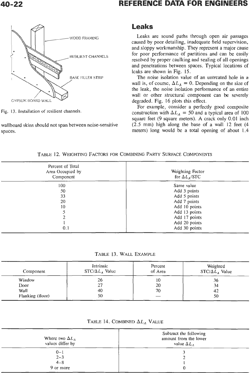
For ceilings and walls, resilient channels might
typically be attached 24 inches
on
center at right angles
to the floor joists or studs. Gypsum board is then
attached to the channels with screws (Fig. 13).
For wall installations, manufacturers often recom-
mend that a 3-inch-wide continuous filler strip be
applied at the base. This will provide good mechanical
support for the baseboard and gypsum board against
damage without sacrificing much resilience.
Weighting
of
Components
Each structural component (window, door, ceiling
plenum, etc.) in a composite wall or sound path will
contribute sound energy to the receiving room in
proportion to the percentage of the total area occupied
by that element. Therefore the
ALA
value for the
element must be weighted to correct for the area it
occupies.
To
weight the contribution
of
each element, use Table
12. For example, a wood solid-core door has a
ALA
rating of 27 when fully gasketed; it occupies 20% of the
wall area with a neighboring office. Therefore, its
weighted contribution to the noise reduction between
rooms is 27
+
7
=
34
ALA.
By looking at the weighted
ALA
value for each
structural component or flanking path or leak (de-
scribed later), it is readily apparent what the controlling
noise path
is
in any isolation analysis. Consider the
40-20
REFERENCE
DATA
FOR ENGINEERS
1
2
x
4
WOOD STUDS.
16'
ON
CENTER WITH
1:
2'
GYPSUM BOARD
ON EACH SIDE
INSULATION ADDED
II\i
THE AIR SPACE
RESILIENT CHANNELS
ADDED ON ONE SIDE
2 2
x
4
WOOD STUDS.
STAGGERED ON
2
x
6
PLATE
WITH TWO LAYERS OF
112'.
GYPSUM BOARD
ON
EACH SIDE
3
2
x
4
WOOD STUDS,
DOUBLED. EACH ON
SEPARATE PLATE WITH
3
1
,'Z'
INSULATION
IN AIR SPACE
OF THE BASIC PARTITION ARE SUMMARIZED BELOW
1.
BASIC PARTITION.
1LAISTC
37
3s
H
2
112
STEEL SCREW STUDS
24' ON CENTER.SINGLE LAYER
OF
112"GYPSUM BOARD ON EACH SIDE
(SUBSTITUTION OF
518"
WALLBOARD
WILL NOT SUBSTANTIALLY CHANGE
THE
ALA
RATING
)
2 ADD
1"
OF GLASS FIBER INSULATION
a
,-~
ADD5
OR
1
LAYER
OF
WALLBOARD.
4
ADD WALLBOARD TO OTHER SIDE ADD3
5
ADD ADDITIOKAL GLASS FIBER ADD
2
INSULATION UP TO
3"
PER INCH
~LA/STC
:35
3.1
(9
:ix
44 4:3
46
44
(A)
Wood
stud
fmrnlng
1
4'
DENSE HOLLOW-CORE BLOCK,
PAINTED
M
PLASTER ADDED ON BOTH SIDES
2
6'
DENSE HOLLOW-CORE,
PAINTED,
3
X"
DENS€ HOLLOW CORE WITH
4"
BRICK ONE SIDE
4
X"
LIGHTWEIGHT BLOCK
SUBTRACT
1
6.
IF
MORE THAN TWO ADDITIONS,
SUBTRACT
1
PAINTED
7
FOR
1-5/8"
STUDS. SUBTRACT
1
FOR
3~518'
STUDS
1
x
2 FURRING
16
0
C WITH
1/2
GYPSUM BOARD ADDED
ON ONE SIDE
ALAISTC
41 38
45 42
rgJ
44 43
rgl
45 45
/zh
50 50
(E)
Metal
stud
portitlons.
Fig.
10.
Interior-wall sound isolation.
IC)
Concrete
and concrete
block
ELECTROACOUSTICS
FINISHED WOOD FLOOR
112
PLYWOOD SUBFLOOR
2
x
10
WOOD JOISTS
40-21
-LL
It
k
I
WITH PLYWOOD SHEATHING AND
~LA/STC
WOOD SIDING, OR FIBER BACKING
BOARD AND METAL SIDING, WITH
INSULATION
'
38
44
WITH RESILIENT CHANNELS
* *
57
WITH RESILIENT CHANNELS."
WITH BRICK VENEER
56
*
It is assumed that all new
wood
frame construction
would
have
glass
fiber
or
mineral wool insulation in the stud cavity
*
*Always
use sound-absorptive insulation with resilient channels
(A)
Wood
stud
framing.
CONCRETE BLOCK WITH
4'
EXTERIOR FACE BRICK.
WITH 2 INCH
15
mm)
RIGID INSULATION WITH
INTERIOR GYPSUM BOARD
ALAISTC
55
POURED CONCRETE
8
INCHES
(20
mm)
THICK WITH
2 INCH
(5
rnm)
RIGID
INSULATION WITH IKTERIOR
GYPSUM BOARD
1A
16
ONCENTER
5/8
GYPSUM BOARD
1B WITH RESILIENT CHANNELS
AND INSULATION
*
L
2
15
8
LIGHTWEIGHT
rtQ'$
O0
COhCRETE
160
LBS PER
CUBIC FOOT1
1
2 PLYWOOD
2
x
10
WOOD
JOISTS
16"
ON CENTER WITH
RESILIENT CHANNELS AND
INSULATION
'
3
FINISHED WOOD OR VINYL
FLOOR
8'
PRECAST
CONCRETE PANEL
4
FINISHED WOOD
OR
VINYL
FLOOR.
2"
CONCRETE FILL
ON METAL DECK.
16"
DEEP
STEEL BAR JOISTS. 24" ON
CENTER WITH CHANNELS
AND INSULATION,
ALA
/STC
38
37
46
45
53
53
50
50
55
55
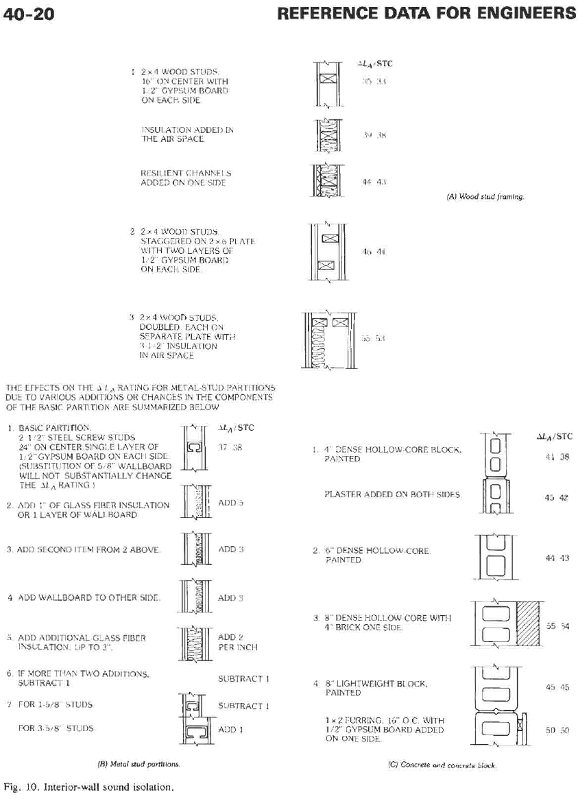
Insulation
and
resilient channels
should
alwa~s
be used together
Fig.
12.
Floor/ceiling-system
sound
isolation.
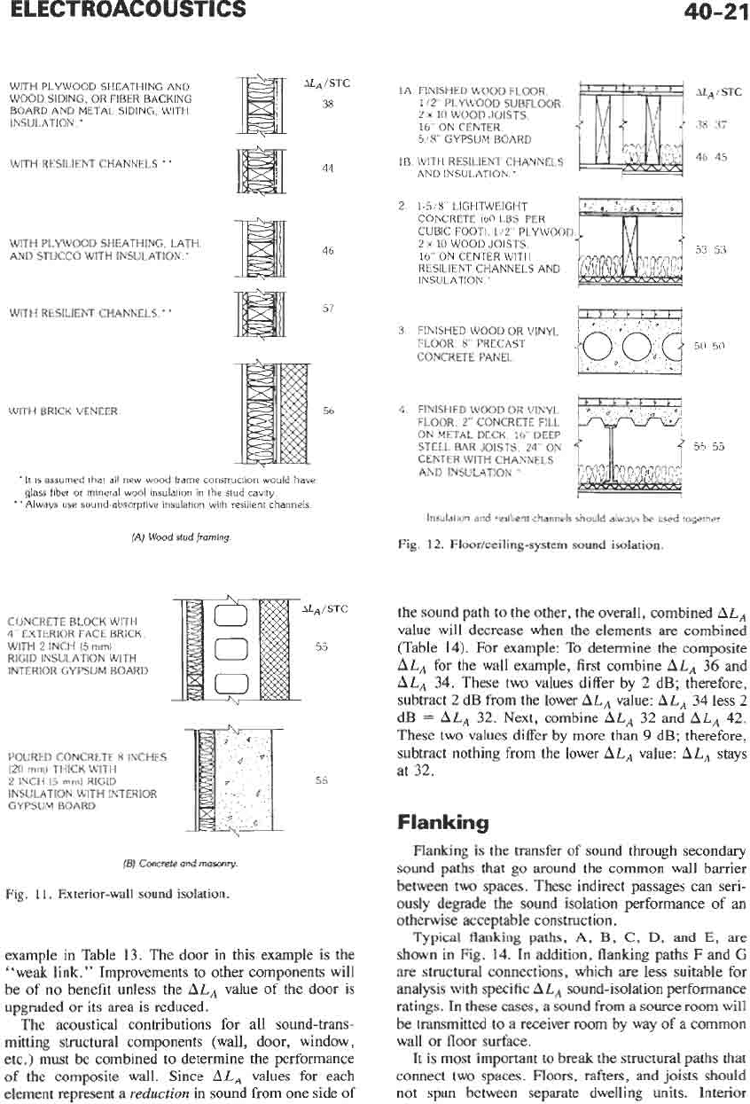
the sound path to the other, the overall, combined
ALA
value will decrease when the elements are combined
(Table 14). For example: To determine the composite
ALA
for the wall example, first combine
ALA
36 and
ALA
34. These two values differ by 2 dB; therefore,
subtract
2
dB from the lower
ALA
value:
ALA
34 less
2
dB
=
ALA
32. Next, combine
ALA
32 and
ALA
42.
These two values differ by more than
9
dB; therefore,
subtract nothing from the lower
ALA
value:
ALA
stays
at 32.
55
Flanking
(B)
Concrete
and
masonry.
Fig. 11. Exterior-wall
sound
isolation.
example in Table 13. The door in this example is the
"weak link." Improvements to other components will
be of
no
benefit unless the
ALA
value of the door is
upgraded or its area is reduced.
The acoustical contributions for all sound-trans-
mitting structural components (wall, door, window,
etc.) must be combined
to
determine the performance
of
the composite wall. Since
ALA
values for each
element represent a
reduction
in sound from one side of
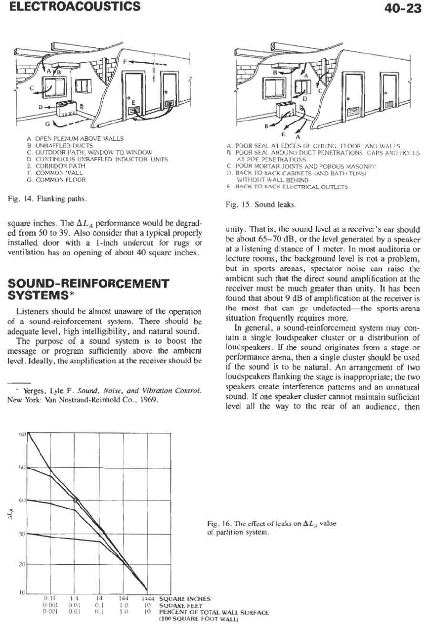
Flanking is the transfer
of
sound through secondary
sound paths that go around the common wall barrier
between two spaces. These indirect passages can seri-
ously degrade the sound isolation performance
of
an
otherwise acceptable construction.
Typical
flanking
paths,
A,
B,
C,
D,
and
E,
are
shown in Fig.
14.
In addition, flanking paths F and
G
are structural connections, which are less suitable for
analysis with specific
A LA
sound-isolation performance
ratings.
In these cases, a sound from a source room will
be transmitted to a receiver room by way of a common
wall or floor surface.
It
is most important to break the structural paths that
connect two spaces. Floors, rafters, and joists should
not span between separate dwelling units. Interior
Leaks
WOOD
FRAMING
Leaks are sound paths through open air passages
caused by poor detailing, inadequate field supervision,
and sloppy workmanship. They represent a major cause
for poor performance
of
partitions and can be easily
resolved by proper caulking and sealing of all openings
and penetrations between spaces. Typical locations
of
leaks
are
shown in Fig. 15.
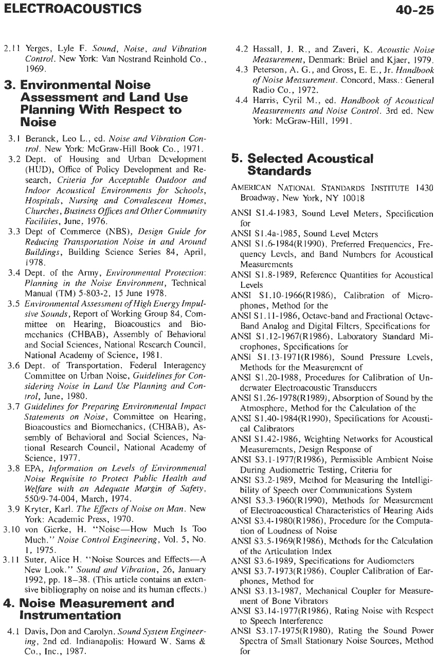
The noise isolation value
of
an untreated hole in a
wall is,
of
course,
ALA
=
0.
Depending on the size
of
the leak, the noise isolation performance
of
an entire
wall
or
other structural component can be severely
degraded. Fig. 16 plots this effect.
For
example, consider a perfectly good composite
construction with
ALA
=
50
and a typical area of 100
square feet
(9
square meters).
A
crack only 0.01 inch
(2.5 mm) high along the base
of
a wall 12 feet (4
meters) long would be a total opening of about 1.4
RESILIENT
CHANNELS
ASE FILLER STRIP
Fig. 13. Installation
of
resilient channels.
wallboard skins should not span between noise-sensitive
spaces.
Percent
of
Total
Area Occupied by
Component
TABLE
12.
WEIGHTING
FACTORS
FOR COMBINING PARTY
SURFACE
COMPONENTS
Weighting Factor
for
AL,ISTC
100
50
33
20
10
5
2
1
0.1
Same value
Add
3
points
Add
5
points
Add
7
points
Add 10 points
Add 13 points
Add
17
points
Add
20
points
Add
30
points
Component
TABLE
14.
COMBINED
ALA
VALUE
Intrinsic
Percent Weighted
STCIALA
Value
of
Area
STCIA LA
Value
Where two
ALA
values differ
by
Window
Door
Wall
Flanking (floor)
Subtract
the
following
amount from the lower
value
ALA
26
10
36
27 20
34
40
70
42
50
50
-
0-
1
2-3
4-8
9
or
more
ELECTROACOUSTICS
40-23
A OPEN PLENUM ABOVE WALLS
B UNBAFFLED DUCTS
C OUTDOOR PATH, WINDOW
TO
WINDOW
D CONTINUOUS UNBAFFLED INDUCTOR UNITS
E CORRIDOR PATH
F
COMMONWALL
G COMMON FLOOR
Fig.
14.
Flanking paths.
A POOR SEAL AT EDGES OF CEILING FLOOR AND L4ALLS
B
POOR SEAL AROUND DUCT PENETRATIONS GAPS AND HOLES
AT PIPE PENETKATlONS
C POOR MORTAR JOINTS AND POROUS MASONRY
11
BACK TO BACK CABINETS (AkD BATH TUBS)
WlrHOUT WALL BEHIND
E BACK
TO
BACK ELECTRICAL OUTLETS
Fig.
15.
Sound
leaks.
square inches. The
ALA
performance would be degrad-
ed from
5o
to
39.
Also consider
that
a
typical
properly
ventilation has an opening of ahout
40
square inches.
unity. That is, the sound level at a receiver's ear should
at a listening distance
of 1
meter. In most auditoria or
lecture rooms, the background level is not a problem,
installed door with
a
l-inch undercut for rugs
or
be
about
65-70
dB
9
Or
the
level generated by a speaker
SOUND-REINFORCEMENT
SYSTEMS*
-
but in sports arenas, spectator noise can raise the
abient such that the direct sound amplification at the
receiver must be much greater than unity. It has been
found that about
9
dB of amplification at the receiver is
Listeners should be almost unaware of the operation
of a sound-reinforcement system. There should be situation requires
more'
adequate level, high intelligibility, and natural sound.
The
purpose of
a
sound
system
is to
boost the
message or program sufficiently above the ambient
level. Ideally, the amplification at the receiver should be
the
most
that
can
go undetected-the sports-arena
In general, a sound-reinforcement system may con-
tain a single loudspeaker cluster or a distribution of
loudspeakers. If the sound originates from a stage or
performance
be
used
if the sound is to be natural. An arrangement of two
then
a sing1e 'luster
I
loudspeakers flanking the stage is inappropriate; the two
speakers create interference patterns and an unnatural
sound. If one speaker cluster cannot maintain sufficient
level all the way to the rear of an audience, then
Yerges,
Lyle F,
Sound,
Noise,
and
Vibration
control,
New
York: Van
Nostrand-Reinhold
Co.,
1969.
60
50
40
4
4
Fig.
16.
The
effect
of
leaks
on
ALA
Value
30
of
partition system.
0
14
14
14 144 1444
SQUAREINCHES
0001
001
0
1
10
10
SQUAREFEET
0 001
0
01
0
I
1
0
10
PERCENT OF TOTAL WALL SURFACE
(100
SQUARE FOOT WALL)
additional speakers can be added closer to the rear with
appropriate time-delay hardware
so
that the sound
remains realistic and in correct time phase with the
source. Distributed loudspeaker systems
are
used when
there is no identifiable source. Situations requiring
distributed systems include paging, such as in offices,
and background music, such as
in
food stores.
A rule of thumb for placing loudspeakers in a
distributed system is:
D
=
2(H
-
4)
where,
D
=
distance between speaker centers in feet,
H
=
ceiling height in feet.
or
D
=
2(H
-
1)
where
D
and
H
are in meters.
The center
of
a single speaker should be aimed at the
most distant centrally located receiver. The directivity
pattern (vertically and horizontally) should be chosen to
provide a uniform sound field to the audience given the
elevation and plan of the room.*
REFERENCES ON
ENVIRONMENTAL NOISE
1.
Schultz, Theodore J., “Synthesis of social surveys
on
noise annoyance.”
Journal of the Acoustical
Society of America,
64(2): August 1978, pp. 337-
405.
2.
Public Health and Welfare Criteria for Noise.
US
Environmental Protection Agency Office of Noise
Abatement and Control. Report Number 55019-73-
002, July 27, 1973.t
3.
Information
on
Levels of Environmental Noise Req-
uisite
to
Protect Public Health and Weyare with an
Adequate Margin
of
Safety.
U.S.
Environmental
Protection Agency Office
of
Noise Abatement and
Control, Report Number 550/9-74-004, March
1974.t
4.
American National Standard Quantities and Proce-
dures for Description and Measurement of Environ-
mental
Sound.
Part
1.
American National Standards
Institute
(ANSI)
Standard
S12.9-1988.
5.
Guidelines for Considering Noise
In
Land Use
Planning and Control.
Federal Interagency Com-
mittee on Urban Noise, June 1980.
6.
Army Regulation 200-1, 1990.
Environmental Pro-
tection and Enhancement, Chapter
7.
Environmen-
-
*
Sound
systems
in
large and/or critical areas
(e.g.,
playhouses
are
dealt with in reference
4.1.
t
The
best summary
of
references
2
and
3
is:
Protective
Noise Levels-Condensed Version
of
EPA
Levels Document.
US
Environmental Protection Agency, EPA 550/9-79-100,
November 1978.
tal Noise Abatement Program. Department
of
the
Army, Washington D.C., 23 April 1990.
7. Annoyance, Loudness, and Measurement of Repeti-
tive Type Impulsive Noise Sources.
US
Environmen-
tal Protection Agency Office of Noise Abatement
and Control, Report Number 55019-79-103, No-
vember 1979.
SELECTED BIBLIOGRAPHY
1.
General Acoustics
1.1
Kinder, Frey, Coppens, and Sanders.
Fundamen-
tals
of
Acoustics.
3rd ed. New York: John Wiley
and
Sons,
Inc., 1982.
1.2 Morse and Ingard.
Theoretical Acoustics.
New
York McGraw-Hill
Book
Co., 1968.
1.3 Rayleigh, J.
The Theory
of
Sound.
New York:
Dover Publications, 1945 (from the 1894 edi-
tion).
1.4 Swenson, George
W.
Principles
of
Modern
Acoustics.
New York: Van Nostrand, 1953.
1.5
Pierce, Allan
D.
Acoustics.
Woodbury, NY:
Acoustical Society of America, 1989.
2.
Building Acoustics
2.1 Department of Housing and Urban Development
(HUD),
A Guide
to
Airborne, Impact and Struc-
ture Borne Noise Control in Multi-Family Dwell-
ings,
FT/TS-24, 1967.
2.2 Dept. of Commerce,
Acoustical and Thermal
Performance
of
Exterior Residential Walls, Doors
and Windows,
NBS Building Science Series
No.
77, Nov., 1975.
2.3
Acoustical Manual: Apartment and Home Con-
struction.
Rockville, Md.
:
National Association
of
House Builders (NAHB), Research Founda-
tion, No. 315.04, June, 1971.
2.4
Guide and Data Book.
New York: American
Society of Heating, Refrigeration and Air-Condi-
tioning Engineers (ASHRAE).
2.5 Ginn, K.
Architectural Acoustics.
Denmark:
Briiel and Kjaer, 1978.
2.6 Knudsen and Harris.
Acoustical Design in Archi-
tecture.
New York John Wiley and Sons, Inc.,
1950.
2.7 Newman, R., et al.
Acoustics, Time Saver Stan-
dard.
New York: McGraw-Hill Book Co., 1973.
2.8
Dept.
of
Commerce,
Quieting: A Practical Guide
to
Noise Control,
NBS
Handbook
No.
119, July,
1971.
2.9 Sound Research Laboratories, Ltd.
Practical
Building Acoustics.
London:
E.
and
F.
N. Spon,
Ltd.; or New York: Halsted Press, a division
of
John Wiley and Sons, Inc.; 1976.
2.10
Sweet’s Architectural Catalog File.
New York:
Sweet’s Division of McGraw-Hill Information
Systems Co.
2.11 Yerges, Lyle F.
Sound, Noise, and Vibration
Control.
New York Van Nostrand Reinhold Co.,
1969.
4.2 Hassall, J. R., and Zaveri, K.
Acoustic Noise
Measurement,
Denmark: Bruel and Kjaer, 1979.
4.3 Peterson, A. G., and Gross,
E.
E., Jr.
Handbook
3.
Environmental Noise
Assessment and Land Use
Noise
Planning With Respect to
Measurements and Noise Control.
3rd ed. New
York: McGraw-Hill, 1991.
of
Noise Measurement.
Concord, Mass.: General
Radio Co., 1972.
4.4 Harris; Cyril M., ed.
Handbook
of
Acoustical
3.1
3.2
3.3
3.4
3.5
3.6
3.7
3.8
3.9
3.10
3.11
Beranek, Leo L., ed.
Noise and Vibration Con-
trol.
New York: McGraw-Hill Book Co., 1971.
Dept. of Housing and Urban Development
(HUD), Office
of
Policy Development and Re-
search,
Criteria for Acceptable Outdoor and
Indoor Acoustical Environments for Schools,
Hospitals, Nursing and Convalescent Homes,
Churches, Business Ofices and Other Community
Facilities,
June, 1976.
Dept of Commerce (NBS),
Design Guide for
Reducing Transportation Noise in and Around
Buildings,
Building Science Series 84, April,
1978.
Dept. of the Army,
Environmental Protection:
Planning in the Noise Environment,
Technical
Manual (TM) 5-803-2,
15
June 1978.
Environmental Assessment of High Energy Impul-
sive Sounds,
Report of Working Group 84, Com-
mittee on Hearing, Bioacoustics and Bio-
mechanics (CHBAB), Assembly of Behavioral
and Social Sciences, National Research Council,
National Academy of Science,
1981.
Dept
.
of
Transportation, Federal Interagency
Committee on Urban Noise,
Guidelines for Con-
sidering Noise in Land
Use
Planning and Con-
trol,
June,
1980.
Guidelines for Preparing Environmental Impact
Statements
on
Noise,
Committee on Hearing,
Bioacoustics and Biomechanics, (CHBAB), As-
sembly of Behavioral and Social Sciences, Na-
tional Research Council, National Academy of
Science, 1977.
EPA,
Information
on
Levels
of
Environmental
Noise Requisite
to
Protect Public Health and
Welfare with an Adequate Margin
of
Safety,
550/9-74-004, March, 1974.
Kryter, Karl.
The Effects
of
Noise
on
Man.
New
York: Academic Press, 1970.
von Gierke, H. “Noise-How Much Is Too
Much.”
Noise Control Engineering,
Vol.
5,
NO.
1,
1975.
Suter, Alice H. “Noise Sources and Effects-A
New Look.”
Sound
and Vibration,
26, January
1992, pp. 18-38. (This article contains an exten-
sive bibliography
on
noise and its human effects.)
5.
Selected Acoustical
Standards
AMERICAN NATIONAL STANDARDS INSTITUTE 1430
ANSI S1.4-1983, Sound Level Meters, Specification
ANSI S1.4a-1985, Sound Level Meters
ANSI S1.6-1984(R1990), Preferred Frequencies, Fre-
quency Levels, and Band Numbers for Acoustical
Measurements
ANSI
S1.8-1989,
Reference Quantities for Acoustical
Levels
ANSI Sl.10-1966(R1986), Calibration of Micro-
phones, Method for the
ANSI
S1.ll-1986, Octave-band and Fractional Octave-
Band Analog and Digital Filters, Specifications for
ANSI S1.12-1967(R1986), Laboratory Standard Mi-
crophones, Specifications for
ANSI S1.13-1971(R1986), Sound Pressure Levels,
Methods for the Measurement
of
ANSI S1.20-1988, Procedures for Calibration of Un-
derwater Electroacoustic Transducers
ANSI S1.26-1978(R1989), Absorption of Sound by the
Atmosphere, Method for the Calculation of the
ANSI S1.40-1984(R1990), Specifications for Acousti-
cal Calibrators
ANSI S1.42-1986, Weighting Networks for Acoustical
Measurements, Design Response
of
ANSI S3.1-1977(R1986), Permissible Ambient Noise
During Audiometric Testing, Criteria for
ANSI S3.2-1989, Method for Measuring the Intelligi-
bility of Speech over Communications System
ANSI S3.3-1960(R1990), Methods for Measurement
of Electroacoustical Characteristics of Hearing Aids
ANSI S3.4-1980(R1986), Procedure for the Computa-
tion of Loudness of Noise
ANSI S3.5-1969(R1986), Methods for the Calculation
of
the
Articulation Index
ANSI S3.6-1989, Specifications for Audiometers
ANSI S3.7-1973(R1986), Coupler Calibration of Ear-
ANSI S3.13-1987, Mechanical Coupler for Measure-
ANSI S3.14-1977(R1986), Rating Noise with Respect
Broadway, New York, NY 100
18
for
phones, Method for
ment of Bone Vibrators
to SDeech Interference
4.
Noise Measurement and
Instrumentation
4.1 Davis, Don and Carolyn.
SoundSystem Engineer-
ing,
2nd ed. Indianapolis: Howard
W.
Sams
&
Co.,
Inc., 1987. for
ANSI ‘S3.17-1975(R1980), Rating the Sound Power
Spectra of Small Stationary Noise Sources, Method
ANSI S3.18-1979(R1986), Whole-Body Vibration,
Guide for the Evaluation of Human Exposure to
ANSI S3.19-1974(R1990), Method for Measurement
of Real-Ear Protection of Hearing Protectors and
Physical Attenuation of Earmuffs
ANSI S3.20-1973(R1978), Psychoacoustical Terminol-
ogy
ANSI S3.21- 1978(R1986), Manual Pure-Tone Thresh-
old Audiometry, Method for
ANSI S3.22-1987, Hearing Aid Characteristics, Speci-
fication
of
ANSI S3.36-1985(R1990), Specification for Manikin
for Simulated in Situ Airborne Acoustic Measure-
ments
ANSI S3.37-1987, Preferred Earhook Nozzle Thread
for Postauricular Hearing Aids
ANSI S3.39- 1987, Specifications for Instruments to
Measure Aural Acoustic Impedance and Admittance
(Aural Acoustic Immittance)
ANSI S12.7-1986, Methods for Measurement of lm-
pulse Noise
ANSI S12.8-1987, Methods for Determination of In-
sertion Loss of Outdoor Noise Barriers
ANSI
S
12.9-1988, Quantities and Procedures for De-
scription and Measurement of Environmental Sound,
Part
I
ANSI S12.10-1985(R1990), Methods for the Measure-
ment and Designation of Noise Emitted by Computer
and Business Equipment
ANSI S12.1-1983, Preparation of Standard Procedures
to Determine the Noise Emission from Sources,
Guidelines for the
ANSI S12.3-1985(R1990), Statistical Methods for De-
termining and Verifying Stated Noise Emission Val-
ues of Machinery
and
Equipment
ANSI S12.4-1986, Method for Assessment of High-
Energy Impulsive Sounds with Respect to Residential
Communities
ANSI S12.5-1990, Reference Sound Sources, Require-
ments for the Performance and Calibration
of
ANSI S12.6-1984(R1990), Method for the Measure-
ment
of
the Real-Ear Attenuation of Hearing Protec-
tors
ANSI S12.11-1987, Methods for the Measurement of
Noise Emitted by Small Air-Moving Devices
ANSI S12.23-1989, Method for the Designation of
Sound Power Emitted by Machinery and Equipment
ANSI S12.30-1990, Sound Power Standards and the
Preparation of Noise Test Codes, Guidelines for the
Use of
ANSI S12.31-1990, Broad-Band Noise Sources in
Reverberation Rooms, Precision Methods for the
Determination of Sound Power Levels
of
ANSI S12.32-1990, Discrete-Frequency and Narrow-
Band Noise Sources in Reverberation Rooms, Preci-
sion Methods for the Determination of Sound Power
Levels of
ANSI S12.33-1990, Sound Power Levels of Noise
Sources in a Special Reverberation Test Room,
Engineering Methods for the Determination of
ANSI S12.34-1988, Free-Field Conditions over a Re-
flecting Plane, Engineering Methods for the Determi-
nation of Sound Power Levels of Noise Sources for
Essentially
ANSI S12.35-1990, Sound Power Levels of Noise
Sources in Anechoic and Hemi-Anechoic Rooms,
Determination of
ANSI S12.36-1990, Sound Power Levels of Noise
Sources, Survey Methods for the Determination of
(redesignation of ANSI
SI
.36-1979)
ANSI S12.40-1990, Compatible Land Use, Sound
Level Descriptors for Determination of
ANSI PH22.202M-1984, B Chain Electro-Acoustic
Response-Control Rooms and Indoor Theaters
INTERNATIONAL
STANDARDS
ORGANIZATION (ISO)
Central Secretariat, Case Postale 56, CH-1211, Ge-
neva
20,
Switzerland
IS0 362: 1981, Acoustics-Measurement of noise
emited by accelerating road vehicles-Engineering
method
Amendment 01-1985
Ed.
I
4p. CodeC TC43 HB4
Ed.
I
I
p.
Code
A
TC43
IS0 1680-1:1986, Acoustics-Test code for the mea-
surement of airborne noise emitted by rotating elec-
trical machinery-Part
1:
Engineering method for
free-field conditions over a reflecting plane
Ed.
I
15p. Code
J
TC43
IS0 1680-2:1986, Acoustics-Test code for the mea-
surement
of
airborne noise emitted by rotating elec-
trical machinery-Part
2:
Survey method
Ed.
1
14p. Code
H
TC43
IS0 2151:1972, Measurement of airborne noise emit-
ted by
compressor/primemover-units
intended for
outdoor use
(To
be replaced by future IS0 3989 of
TC 43)
Ed.
I
7p. CodeD TCII8 HB4
IS0 2922: 1975, Acoustics-Measurement
of
noise
emitted by vessels on inland water-ways and harbours
IS0
2923: 1975, Acoustics-Measurement
of
noise on
Ed.
1
4p. Code C TC43 HB
4
board vessels
Ed.
I
4p. Code C TC43 HB
4
IS0
3095: 1975, Acoustics-Measurement
of
noise
emitted by railbound vehicles
Ed.
I
6p.
Code
D
TC 43 HB
4
IS0 3381:1976, Acoustics-Measurement of noise
inside railbound vehicles
Ed.
I
4p. Code C TC43 HB
4
IS0
3891: 1978, Acoustics-Procedure for describing
aircraft noise heard on the ground
Ed.
I
24p. Code
N
TC 43 HB 4
IS0
4412-1:1979, Hydraulic fluid power-Test code
for the determination of airborne noise levels-Part
1: Pumps
Ed.
I
6p.
Code
D
TC 131 HB
25
IS0 4412-2: 1984, Hydraulic fluid power-Test code
40-27
for the determination of airborne noise levels-Part
2: Motors
Ed. 1 6p. Code D TC 131 HB 25
IS0
4871: 1984, Acoustics-Noise labelling of machin-
ery and equipment
Ed.
I
5p. Code D TC43 HB 4
IS0
4872: 1978, Acoustics-Measurement of airborne
noise emitted by construction equipment intended for
outdoor use-Method for checking compliance with
noise limits
Ed. 1 11 p. CodeG TC43 HB4
IS0
5128: 1980, Acoustics-Measurement of noise
inside motor vehicles
Ed. 1 6p. Code D TC43 HB 4
IS0
5129: 1987, Acoustics-Measurement of noise
inside aircraft
Ed. 2 4p. Code
C
TC43
IS0
5
130: 1982, Acoustics-Measurement of noise
emitted by stationary road vehicles-Survey method
IS0 5131:1982, Acoustics-Tractors and machinery
for agriculture and forestry-Measurement of noise
at the operator’s position-Survey method
Ed.
1
8p. Code E TC43 HB 4
Ed. 1 6p. Code D TC43 HB
4
IS0
5
135: 1984, Acoustics-Determination of sound
power levels of noise from air terminal devices,
high/low velocity/pressure assemblies, dampers and
valves by measurement in a reverberation room
Ed. 1 11 p. CodeG TC43 HB4
IS0 6081: 1986, Acoustics-Noise emitted by machin-
ery and equipment-Guidelines for the preparation
of test codes of engineering grade requiring noise
measurements at the operator’s
or
bystander’s posi-
tion
Ed.
I
9p. Code
F
TC 43
IS0
6190:1988, Acoustics-Measurement of sound
pressure levels of gas turbine installations for evaluat-
ing environmental noise-Survey method
Ed. 1 6p. Code D TC 43
IS0
6393: 1985, Acoustics-Measurement of airborne
noise emitted by earth-moving machinery-Method
for determining compliance with limits for exterior
noise-Stationary test condition
Ed. 1 7p. CodeE TC43 TC127 HB4
IS0
6394: 1985, Acoustics-Measurement of airborne
noise emitted by earth-moving machinery-
Operator’s position-Stationary test condition
Ed.
I
5p. CodeD TC43 TC127 HB4
IS0
6395: 1988, Acoustics-Measurement
of
exterior
noise emitted by earth-moving machinery-
Dynamic test conditions
Ed.
I
13p. CodeH TC43 TC127
IS0 7182: 1984, Acoustics-Measurement at the oper-
ator’s position
of
airborne noise emitted by chain
saws
Ed. 1 3p. Code
C
TC43 TC23 HB4
IS0
7188:1985, Acoustics-Measurement of noise
emitted by passenger cars under conditions represen-
tative of urban driving
Ed. 1
5p.
Code
D
TC 43 HB 11
IS0
7574-1: 1985, Acoustics-Statistical methods for
determining and verifying stated noise emission val-
ues
of
machinery and equipment-Part
1:
General
considerations and definitions
Ed.
I
4p. Code C TC43
IS0 7574-2: 1985, Acoustics-Statistical methods for
determining and verifying stated noise emission val-
ues of machinery and equipment-Part 2: Methods
for stated values for individual machines
Ed.
I
2p. Code B TC 43
IS0
7574-3: 1985, Acoustics-Statistical methods for
determining and verifying stated noise emission val-
ues of machinery and equipment-Part 3: Simple
(transition) method for stated values for batches of
machines
Ed. 1 2p. Code B TC43
IS0 7574-4: 1985, Acoustics-Statistical methods for
determining and verifying stated noise emission val-
ues of machinery and equipment-Part 4: Methods
for stated values for batches of machines
Ed.
I
14p. Code H TC 43
IS0 7779:
1988,
Acoustics-Measurement of airborne
noise emitted by computer and business equipment
ISO/TR 7849: 1987, Acoustics-Estimation of air-
borne noise emitted by machinery using vibration
measurement
Ed.
I
39p. Code
S
TC 43
Ed. 1 20p. Code
L
XC
43
IS0
7917: 1987, Acoustics-Measurement at the oper-
ator’s position of airborne noise emitted by brush
saws
Ed.
I
4p. Code C TC43 TC23
IS0 9295: 1988, Acoustics-Measurement of high-
frequency noise emitted by computer and business
equipment
Ed.
1
11
p. Code G TC43
IS0 9296: 1988, Acoustics-Declared noise emission
values of computer and business equipment
Ed. 1 7p. Code E
XC
43
Standards used in examining the physical and
environmental effects of sound, mechanical vibration
and shock, and in the balancing of machinery. The
standards included are under: basic documents for
noise measurements and limits; noise measurement
of various sources; building acoustics; general acous-
tics; terminology in vibration and shock; balancing
and balancing machines; human exposure to vibra-
tion and shock.
IS0 Handbook 4-Acoustics, vibration and shock
Price group
XZ.
850
pages. (2nd ed. 1985)
ISBN
92-67-10106-4
AMEIUCAN SOCIETY
OF
TESTING
AND
MATERIALS
(ASTM)
1916 Race St., Philadelphia, PA 19103-1187
C 367-78 (Reapproved
89),
Standard Test Methods for
Strength Properties of Prefabricated Architectural
Acoustical Tile of Lay-In Ceiling Panels