Middleton W.M. (ed.) Reference Data for Engineers: Radio, Electronics, Computer and Communications
Подождите немного. Документ загружается.

33-20
REFERENCE
DATA
FOR ENGINEERS
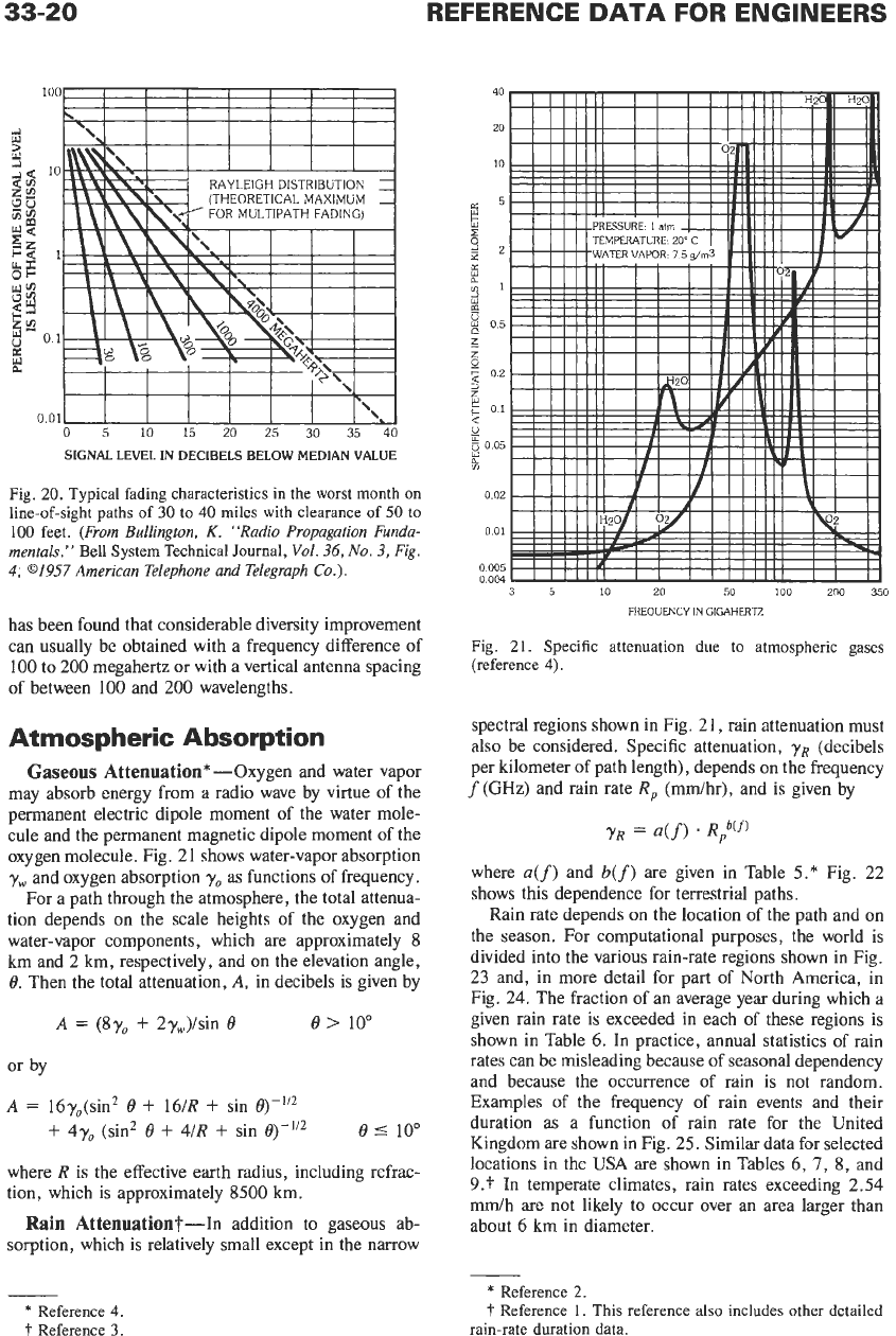
SIGNAL LEVEL IN DECIBELS BELOW MEDIAN VALUE
Fig.
20.
Typical fading characteristics
in
the worst month
on
line-of-sight
paths of
30
to
40
miles
with
clearance of
50
to
100
feet.
(From Bullington,
K.
"Radio Propagation Funda-
mentals."
Bell
System Technical Journal,
Vol.
36,
No.
3,
Fig.
4,
01957
American Telephone and Telegraph
Co.).
has been found that considerable diversity improvement
can usually be obtained with a frequency difference of
100
to 200 megahertz or with a vertical antenna spacing
of between 100 and 200 wavelengths.
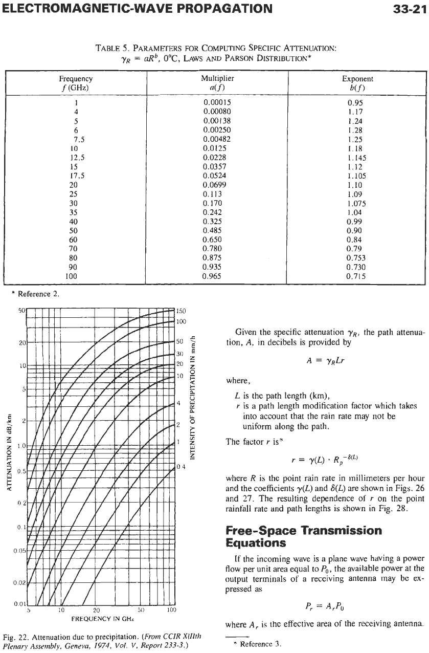
Atmospheric Absorption
Gaseous
Attenuation* -Oxygen and water vapor
may absorb energy from a radio wave by virtue of the
permanent electric dipole moment of the water mole-
cule and the permanent magnetic dipole moment of the
oxygen molecule. Fig. 2 1 shows water-vapor absorption
yw
and oxygen absorption
yo
as functions of frequency.
For a path through the atmosphere, the total attenua-
tion depends on the scale heights of the oxygen and
water-vapor components, which are approximately
8
km and
2
km, respectively, and
on
the elevation angle,
0.
Then the total attenuation,
A,
in decibels is given by
A
=
(8y0
+
2yw)/sin
0
e>
10"
or by
A
=
16yo(sin2
0
+
16/R
+
sin
+
4y0 (sin2
0
+
4/R
+
sin
@-Ii2
0
5
10"
where R is the effective earth radius, including refrac-
tion, which is approximately
8500
km.
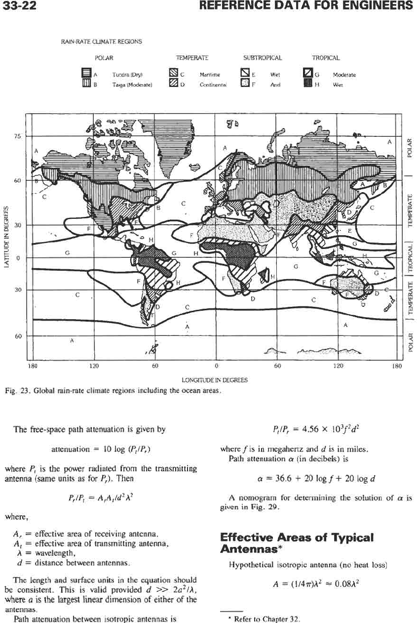
Rain Attenuation?-In addition to gaseous ab-
sorption, which
is
relatively small except in the narrow
40
20
10
0.02
0
01
0
005
0.004
Fig.
21.
Specific attenuation due
to
atmospheric gases
(reference
4).
spectral regions shown
in
Fig.
21,
rain attenuation must
also be considered. Specific attenuation,
yR
(decibels
per kilometer
of
path length), depends
on
the frequency
f(GHz) and rain rate R, (mdhr), and is given by
where
a(f)
and
b(f)
are given in Table
5.*
Fig. 22
shows this dependence for terrestrial paths.
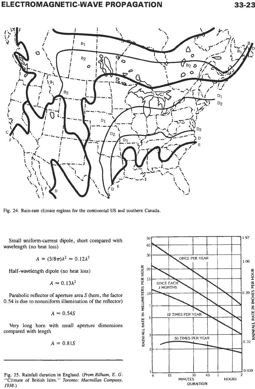
Rain rate depends
on
the location of the path and
on
the season. For computational purposes, the world is
divided into the various rain-rate regions shown in Fig.
23 and, in more detail for part of North America,
in
Fig. 24. The fraction of an average year during which a
given rain rate is exceeded in each of these regions is
shown in Table
6.
In
practice, annual statistics of rain
rates can be misleading because of seasonal dependency
and because the occurrence of rain is not random.
Examples of the frequency of rain events and their
duration as a function of rain rate for the United
Kingdom are shown in Fig. 25. Similar data for selected
locations in the USA are shown in Tables 6,
7,
8,
and
9.t
In temperate climates, rain rates exceeding
2.54
mdh are not likely to occur over an area larger than
about
6
km in diameter.
-
*
Reference
4.
t
Reference
3.
*
Reference
2.
I'
Reference 1.
This
reference
also
includes
other
detailed
rain-rate duration
data.
ELECTROMAGNETIC-WAVE PROPAGATION
TABLE
5.
PARAMETERS
FOR
COMPUTING SPECIFIC ATTENUATION:
YR
=
aRb,
O'C,
LAWS
AND
PARSON
DISTRIBUTION*
Frequency
f
(GW
1
4
5
6
7.5
10
12.5
15
17.5
20
25
30
35
40
50
60
70
80
90
100
Multiplier
a(f
1
0.000
15
0.00080
0.00138
0.00250
0.00482
0.0125
0.0228
0.0357
0.0524
0.0699
0.113
0.
I70
0.242
0.325
0.485
0.650
0.780
0.875
0.935
0.965
33-2
1
Exponent
b(f)
0.95
1.17
1.24
1.28
1.25
1.18
1.145
1.12
1.105
1.10
1.09
1.075
1.04
0.99
0.90
0.84
0.79
0.753
0.730
0.715
*
Reference 2.
Given the specific attenuation
yR,
the path attenua-
tion,
A,
in
decibels is provided by
A
=
yRLr
where,
L
is the path length (km),
r
is a path length modification factor which takes
into account that the rain rate may not be
uniform along the path.
The factor
r
is*
r
=
y(~)
*
R,-'(~)
where
R
is the point rain rate in millimeters per hour
and the coefficients
y(L)
and
S(L)
are shown
in
Figs.
26
and
27.
The resulting dependence of
r
on
the point
rainfall rate and path lengths is shown in Fig.
28.
Free-Space Transmission
Equations
If the incoming wave is a plane wave having a power
flow per unit area equal to
Po,
the available power at the
output terminals
of
a receiving antenna may be ex-
pressed as
Fig. 22. Attenuation due
to
precipitation.
(From
CCZR XllZth
Plenary Assembly, Geneva,
1974,
Vol.
V,
Report
233-3.)
where
A,
is the effective area
of
the receiving antenna.
-
*
Reference 3
33-22
REFERENCE DATA FOR ENGINEERS
75
60
8
K
8
30
z
x
2
5O
30
60
RAIN-RATE CLIMATE REGIONS
POLAR TEMPERATE SUBTROPICAL TROPICAL
A Tundra(Dry1 C Maritime E
Wet
G
Moderate
H
Wet
B
Taiga (Moderate) D Continental
F
Arid
180 120
60
0
60
LONGITUDE IN DEGREES
Fig.
23.
Global rain-rate climate regions including the ocean areas.
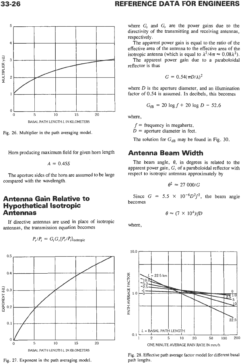
The free-space path attenuation is given by
attenuation
=
10
log
(&/P,)
where
P,
is
the power radiated from the transmitting
antenna (same units as for
P,).
Then
PJP,
=
ArA,/d2A2
where,
A,
=
effective area of receiving antenna,
A,
=
effective area of transmitting antenna,
A
=
wavelength,
d
=
distance between antennas.
The length and surface units in the equation should
be consistent. This is valid provided
d
>>
2a2/A,
where
a
is
the
largest linear dimension
of
either
of
the
antennas.
Path attenuation between isotropic antennas is
120
180
P,/P,
=
4.56
x
103fw
where
f
is
in megahertz and
d
is in miles.
Path attenuation
a
(in decibels) is
a
=
36.6
+
20
log
f
+
20
log
d
A
nomogram for determining the solution
of
a
is
given in Fig.
29.
Effective Areas
of
Typical
Antennas*
Hypothetical isotropic antenna (no heat
loss)
A
=
(1/4r)A2
=
0.08A2
*
Refer
to
Chapter
32.
€2-€E
NOllWOWdOtld
3AWM-3113N0WWOtl13313
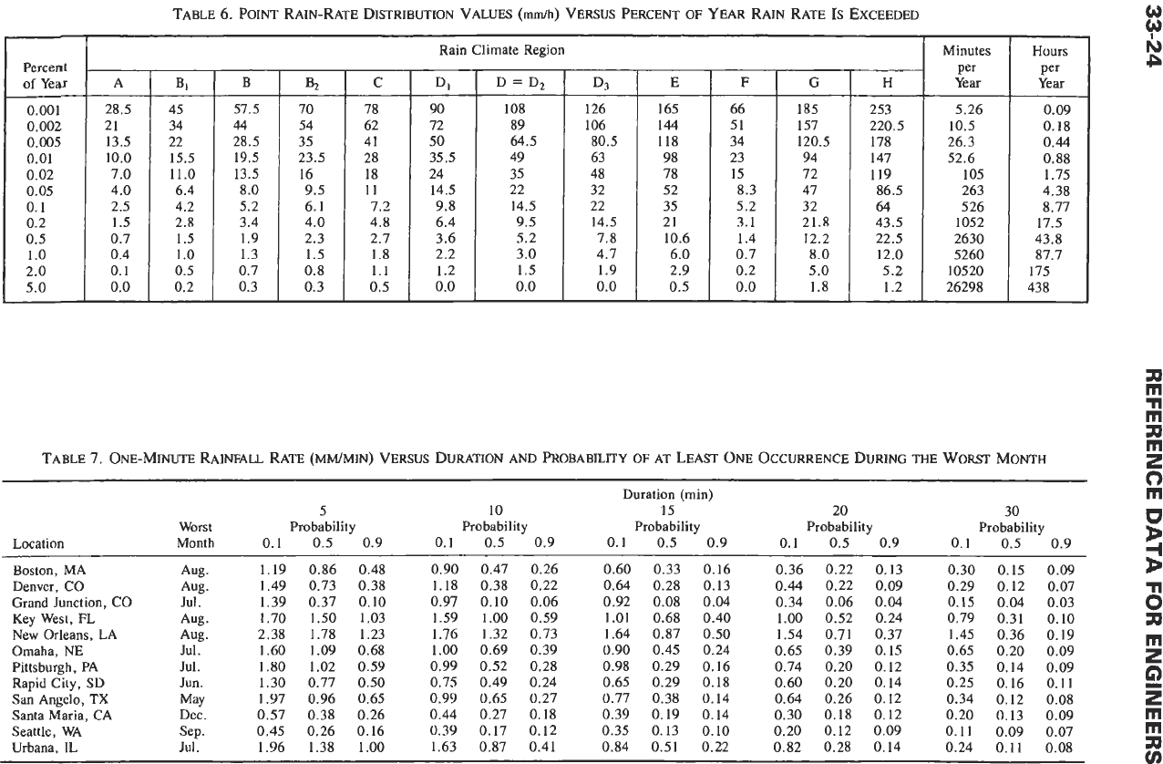
TABLE
6.
POINT RAIN-RATE
DISTRIBUTION
VALUES
(mdh)
VERSUS PERCENT
OF
YEAR
RAIN RATE
IS
EXCEEDED
Percent
of
Year
0.001
0.002
0.005
0.01
0.02
0.05
0.1
0.2
0.5
1
.o
2.0
5.0
Rain Climate Region
I
Minutes
A
B,
28.5 45
21
34
13.5 22
10.0
15.5
7.0 11.0
4.0 6.4
2.5 4.2
1.5 2.8
0.7 1.5
0.4
1
.o
0.1 0.5
0.0
0.2
0.09
0.18
0.44
0.88
1.75
4.38
8.77
17.5
43.8
87.7
175
43
8
TABLE
7.
ONE-MINUTE
RAINFALL
RATE (MM/MIN) VERSUS DURATION AND PROBABILITY
OF
AT
LEAST
ONE OCCURRENCE
DURING
THE WORST
MONTH
Duration (rnin)
5
10
15 20 30
Worst Probability Probability Probability Probability Probability
0.1
0.5 0.9
0.1
0.5
0.9 0.1 0.5 0.9
Location Month
0.1 0.5 0.9
0.1
0.5 0.9
Boston, MA
Denver, CO
Grand Junction, CO
Key West, FL
New Orleans, LA
Omaha,
NE
Pittsburgh, PA
Rapid City,
SD
San Angelo,
TX
Santa Maria, CA
Seattle, WA
Urbana,
IL
Aug.
Aug.
Jul.
Aug
.
Aug.
Jul
.
Jul
.
Jun.
May
Dec.
Sep.
Jul
.
1.19
1.49
1.39
1.70
2.38
1.60
1.80
1.30
1.97
0.57
0.45
1.96
0.86 0.48
0.73 0.38
0.37
0.10
1.50 1.03
1.78 1.23
1.09 0.68
1.02
0.59
0.77 0.50
0.96 0.65
0.38 0.26
0.26 0.16
1.38 1.00
0.90
1.18
0.97
1.59
1.76
1
.oo
0.99
0.75
0.99
0.44
0.39
1.63
0.47 0.26
0.60 0.33
0.16 0.36
0.22
0.13 0.30
0.15
0.09
0.38 0.22
0.64 0.28
0.13
0.44
0.22 0.09
0.29
0.12
0.07
0.10 0.06
0.92 0.08
0.04 0.34
0.06
0.04
0.15 0.04
0.03
1.00
0.59
1.01
0.68
0.40 1.00
0.52 0.24
0.79 0.31
0.10
1.45 0.36 0.19
1.32 0.73 1.64 0.87 0.50 1.54 0.71 0.37
0.65 0.20 0.09
0.69 0.39 0.90 0.45 0.24 0.65 0.39 0.15
0.74 0.20 0.12 0.35 0.14 0.09
0.52 0.28
0.98 0.29 0.16
0.49 0.24
0.65 0.29 0.18 0.60 0.20 0.14 0.25 0.16
0.11
0.65 0.27
0.77 0.38 0.14 0.64 0.26 0.12 0.34
0.12
0.08
0.27 0.18
0.39 0.19
0.14
0.30 0.18 0.12 0.20 0.13 0.09
0.11
0.09 0.07
0.17 0.12 0.35 0.13 0.10 0.20 0.12 0.09
0.87 0.41 0.84 0.51 0.22 0.82 0.28
0.14
0.24
0.11
0.08
n
m
2
G)
z
m
rn
rn
r
rn
Duration (min)
0
5
10
15
20 30
-I
TABLE
8.
ONE-MINUTE
RAINFALL
RATE
(MM~MIN)
VERSUS
DURATION
AND
PROBABILITY
OF
AT
LEAST
THREE
OCCURRENCES
DURING
THE
WORST
MONTH
g
3
Worst Probability Probability Probability Probability Probability
Location Month
0.1
0.5
0.9 0.1
0.5
0.9
0.1
0.5
0.9
0.1
0.5
0.9 0.1
0.5
0.9
0.37 0.24 0.17 0.23
0.15
0.12 0.18 0.13 0.09 0.13 0.09 0.06
Boston, MA Aug.
0.71 0.44 0.33
Denver, Co Aug.
0.53 0.35 0.23 0.32 0.19
0.10
0.22
0.11
0.07 0.14
0.08
0.05
0.09 0.06 0.04
Grand Junction, CO Jul
.
0.26 0.09 0.06 0.09
0.05
0.03 0.06 0.04 0.03
0.05
0.03 0.02 0.04 0.02
0.01
Key West, FL Aug
.
1.32
1.00
0.75 0.84
0.57
0.37 0.57 0.37 0.19 0.42 0.22 0.13 0.23 0.09 0.06
1.10
0.70 0.49 0.72 0.46 0.29
0.50
0.31 0.20 0.29 0.17
0.10
Omaha, NE Jul
.
0.96 0.65 0.44 0.56 0.36 0.20 0.38 0.22 0.11 0.26 0.13
0.08
0.14 0.08
0.05
Pittsburgh, PA Jul
.
0.86 0.56 0.39 0.46 0.27 0.16 0.26 0.15 0.11 0.14 0.11 0.09 0.11
0.08
0.06
0.14 0.10
0.07
Rapid City, SD Jun.
0.67 0.46 0.27 0.41 0.22 0.16 0.24 0.17 0.13
0.18
0.13 0.10
0.42 0.24 0.14 0.26 0.14 0.10
0.15
0.11
0.07
0.10
0.07 0.04
San Angelo,
TX
May
0.81
0.56
0.32
Santa Maria, CA Dec
.
0.33 0.25
0.18
0.23 0.17 0.13 0.17 0.13 0.10
0.15
0.12 0.09 0.12 0.09 0.06
Urbana, IL Jul
.
1.27 0.91 0.63
0.80
0.38 0.23 0.37 0.20 0.12 0.22 0.13
0.08
0.09 0.07
0.05
=
B
c)
2
rn
New Orleans, LA Aug
.
1.70 1.15 0.81
s
g
$
b
Seattle, WA Sep.
0.20 0.15 0.12 0.15 0.12 0.09 0.12 0.09
0.08
0.11 0.09 0.07
0.08
0.07
0.05
<
rn
0
TABLE
9.
LONGEST DURATION
(MIN)
OF
1
MIN
RATES
AT
OR
ABOVE
SPECIFIED
THRESHOLD
RATES
AND THE
MONTH
OF OCCURRENCE
-I
2
5
Threshold Rate jmrn/min)
Location
0.1 0.2 0.4 0.7
1
.o
1.3 1.6 2.0 2.5
Denver,
CO
162
Jun.
47
Aug.
20
Aug.
13
Aug.
12
Aug.
6
Aug.
4
Aug.'
4
Jul.
3
Jul.
Grand Junction, CO
40
Jul.
24
Jul.
19
Jul.
17
Jul.
10
Jul.
8
Jul.
4
Jul.
2
Jul.
1
Jul.
Key West,
FL
156
May
74
Aug.
61
Apr.
39
Apr.
*
22
Aug.
12
Aug.*
10
Aug.
7
Jul.*
4
Jul.'
New Orleans, LA
205
Feb.
96
May*
86
Aug.
61
Aug.
53
Aug.
44
Aug.
24
Nov.
10
Jul.
6
Apr.
Omaha, NE
142
May
67
Jul.
42
Jul.
18
Jul.
12
Jul.*
9
Jul.
5
Jul.*
3
Jul.$
3
Aug.'
Rapid City, SD
149
Jun.
55
Jun.
28
Jul.
16
Jul.
11
Jul.
n
JUI.
n
JUI.
6
Jul.
4
Jul.
San Angelo,
TX
161
Apr.
69
Apr.
35
Apr.
19
May
10
May
8
May
7
May
6
May
3
Jun.
Boston, MA
275
Jan.
52
Sep.
23
Sep.
13
Sep.*
7
Jul.?
7
Jul.
3
Oct.
3
Oct.
1
0ct.t
Pittsburgh, PA
150
May
58
Apr.
27
Jul.
23
Jul.
17
Jul.
7
Jul.'
6
Jul.'
5
Oct.
4
Oct.
Santa Maria, CA
132
Jan.
46
Jan.
19
Sep.
5
Jan.*
3
Jan.
2
Nov.*
2
Nov.'
1
Nov.
0-
Seattle, WA
82
Feb.
59
Oct.
13
Sep.
2
Aug.*
0-
0-
0-
0-
0-
Urbana, IL
91
Oct.
45
May
37
May
25
Jun.
20
Jun.
14
Jun.
10
Jul.*
5
Jul.*
4
May
w
ru
UI
Y
*
Also occurred in one other month.
t
Also occurred in two other months.
$
Also occurred in three other months.
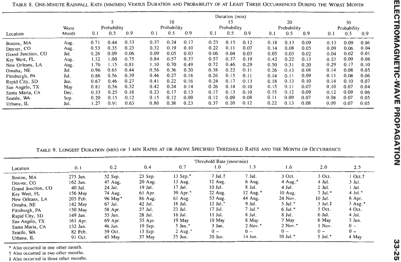
33-26
REFERENCE
DATA
FOR ENGINEERS
0
5
10
15
20
BASAL PATH LENGTH
L
IN
KILOMETERS
Fig.
26.
Multiplier in the path averaging model.
Horn
producing maximum field for given horn length
A
=
0.45s
The aperture sides of the horn are assumed to be large
compared with the wavelength.
Antenna Gain Relative to
Hypothetical Isotropic
Antennas
If
directive antennas are used in place of isotropic
antennas, the transmission equation becomes
PrlPt
=
GI
GrtPrIPtl
isotropic
0.5
0.4
-
2
0.3
+
z
9
g
0.2
0.1
0
BASAL PATH LENGTH
L
IN
KILOMETERS
Fig.
27.
Exponent in the path averaging model.
where
GI
and G, are the power gains due to the
directivity
of
the transmitting and receiving antennas,
respectively.
The apparent power gain is equal to the ratio of the
effective area of the antenna to the effective area
of
the
isotropic antenna (which is equal to
A2/4.rr
=
0.08h2).
The apparent power gain due to a paraboloidal
reflector is thus
G
=
0.54(~D/A)~
where
D
is the aperture diameter, and an illumination
factor of
0.54
is assumed.
In
decibels, this becomes
where,
f
=
frequency in megahertz,
D
=
aperture diameter in feet.
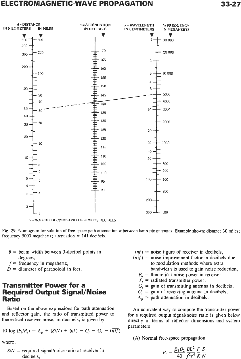
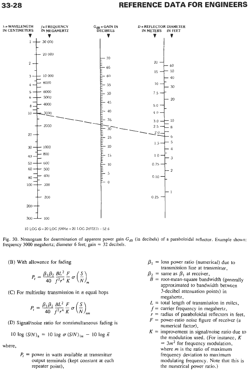
The solution for GdB may be found in Fig.
30.
Antenna Beam Width
The beam angle,
e,
in degrees
is
related to the
apparent power gain,
G,
of a paraboloidal reflector with
respect to isotropic antennas approximately by
e2
=
27
000IG
Since
G
=
5.5
X
10-6D2f2,
the beam angle
becomes
where,
0.1
12
5
10
20
50
100
200
ONE MINUTE
AVERAGE
RA[N
RATE
IN
mm/h
Fig.
28.
Effective path average factor model
for
different basal
path lengths.
ELECTROMAGNETIC-WAVE PROPAGATION
vv
500
-’-
400
--
300
--
200
-
100
-
-
50
40
--
30
20
-
10
-
-
4
--
2-
33-27
300
zoo
-
100
-
-
-
-_
--
50
-
40
-_
30
-
-
--
z0
_-
10
-
-
-
-_
--
5
_-
4
5--3
3--2
-1
A-
u
=
ATTENUATION
IN DECIBELS
A=
WAVELENGTH
f-
FREQUENCY
IN CENTIMETERS IN MEGAHERTZ
20 000
_---
4000
20
50
400
200
a
=
36
6
+
20
LOG
f(MHz)
+
20
LOG
d(MILES)
DECIBELS
Fig.
29.
Nomogram for solution
of
free-space path attenuation
ct
between isotropic antennas. Example shown:
distance
30
miles;
frequency
5000
megahertz; attenuation
=
141
decibels.
0
=
beam width between 3-decibel points in
f
=
frequency in megahertz,
D
=
diameter
of
paraboloid in feet.
degrees,
Transmitter Power for a
Required Output Signal/Noise
Ratio
Based on the above expressions for path attenuation
and reflector gain, the ratio of transmitted power to
theoretical receiver noise, in decibels, is given by
10
log
(PJP,)
=
A,
+
(S/N)
+
(nf)
-
Gt
-
G,
-
(n3)
where,
SIN
=
required signahoise ratio at receiver in
decibels,
(nf)
=
noise figure of receiver in decibels,
to
modulation methods where extra
bandwidth is used to gain noise reduction,
P,
=
theoretical noise power in receiver,
P,
=
radiated transmitter power,
Ct
=
gain of transmitting antenna in decibels,
G,
=
gain of receiving antenna in decibels,
A,
=
path attenuation
in
decibels.
(nif)
=
noise improvement factor in decibels due
An equivalent way
to
compute the transmitter power
for
a
required output signalhoise ratio is given below
directly in terms of reflector dimensions and system
parameters.
(A)
Normal
free-space propagation
33-28
REFERENCE
DATA
FOR
ENGINEERS
h
I
WAVELENGTH FREQIJENCY
IN CENTIMETERS IN MEGAHERTZ
2.
OO~I
--
2c
7
-1
30
200
200
G~B
=
GAIN
IN
DECIBELS
v
D
=
REFLECTOR DIAMETER
IN METERS IN FEET
'
I'
+
60
20
50
40
0
25
10
LOG
G=20
LOGfIMHz)+20
LOG
D(FEET)-52.6
Fig.
30.
Nomogram for determination of apparent power gain
GdB
(in decibels)
of
a
paraboloidal reflector. Example
shown:
frequency
3000
megahertz; diameter
6
feet; gain
=
32
decibels.
(B)
With allowance for fading
(C)
For
multirelay transmission in
n
equal hops
(D)
Signalhoise ratio for nonsimultaneous fading is
10
log
(SIN),
=
10
log
u
(SIN),,
-
10
log
z
where,
PI
=
power in watts available at transmitter
output terminals (kept constant at each
repeater point),
PI
=
loss
power ratio (numerical) due to
P2
=
same as
PI
at receiver,
transmission line at transmitter,
B
=
root-mean-square bandwidth (generally
approximated to bandwidth between
3-decibel attenuation points) in
megahertz,
L
=
total length of transmission in miles,
f
=
carrier frequency in megahertz,
r
=
radius of paraboloidal reflectors in feet,
F
=
power-ratio noise figure of receiver (a
numerical factor),
K
=
improvement in signallnoise ratio due to
the modulation used. (For instance,
K
=
3m2
for frequency modulation,
where
rn
is the ratio
of
maximum
frequency deviation to maximum
modulating frequency. Note that this is
the numerical power ratio.)
ELECTROMAGNETIC-WAVE PROPAGATION
33-29
u
=
numerical ratio between available signal
power in case of normal propagation to
available signal power in case of
maximum expected fading,
SIN
=
required signalhoise power ratio at
receiver,
(SIN),
=
minimum required signalhoise power
ratio in case of maximum expected
fading,
(SIN),,,
=
same as above in case of
n
hops, at
repeater number
n,
(SIN)/,
=
same as above at first repeater,
(S/N),,
=
same as above at end of
n
hops,
n
=
number of equal hops,
rn
=
number of hops where fading occurs,
uh
=
ratio of available signal power for
normal conditions to available signal
power in case of actual fading in hop
number
h
(equation holds in case signal
power is increased instead of decreased
by abnormal propagation
or
reduced
hop distance).
KNIFE-EDGE DIFFRACTION
PROPAGATION*
Diffraction loss at an ideal knife-edge can be estimat-
ed from Fig.
31.
However, the transmission loss over a
practical knife-edge diffraction path depends critically
on the shape of the diffracting edge. Since a natural
obstacle, such as a mountain ridge, may depart consid-
erably from
an
ideal knife-edge, the diffraction loss in
practice is usually
10
to
20
decibels greater than that
estimated for the ideal case.
A nonuniform transverse profile of the diffracting
edge, or reflections on the transmission paths each side
of the diffracting edge, may result in multipath trans-
mission causing variations in the received level as a
function of frequency, space, and time. The amplitude
of such variations may be reduced by either space or
frequency diversity and by the use of narrow-beam-
width antennas.
TROPOSPHERIC SCATTER
PROPAGATION?
Weak but reliable fields are propagated several hun-
dred miles beyond the horizon
in
the very-high-,
-
*
Bullington,
K.
“Radio
Propagation Fundamentals.”
Bell
System
Tech.
J.
Vol. 36,
No.
3,
1957; pp. 593-626.
t
“Estimation
of
Tropospheric-Wave Transmission
Loss
,”
CCIR
XVth
Plenary
Assembly, Geneva,
1982,
Vol.
V,
Report 238-4. Harvey,
A.
F.,
Microwave Engineering,
New
York
Academic Press, Inc., 1963.
ultrahigh-, and superhigh-frequency bands. An impor-
tant parameter in scatter propagation
is
the scatter angle
or
angle
of
intersection of the transmitting and receiving
antenna beams. This angle,
e,
in radians is given by
2d-dt-d,
+‘-
h-H
+u
h
-H
e=
2R
d,
d,
where,
d=
d,
=
d,
=
h,
=
h,
=
H,
=
H,
=
R=
great-circle distance between transmitting
and receiving antennas,
distance
to
the horizon from the transmitting
antenna,
distance to the horizon from the receiving
antenna,
height above sea level of the transmitting
horizon,
height above sea level of the receiving
horizon,
height above sea level of the transmitting
antenna,
height above sea level of the receiving
antenna,
effective radius of the earth.
The same units are used for distances and heights.
The effective radius of the earth is a function of the
refractive index gradient and may be estimated from
Fig.
32.
This curve is based on the correlation found
between the decrease in the refractive index in the first
kilometer
of
altitude above the surface of the earth and
the surface value of the refractive index. Fig.
33
shows
typical mean values of the refractive index at sea level.
The long-term median transmission loss (in decibels)
due to forward scatter is approximately
L(50)
=
30
logf
-
20
log
d
+
F(ed)
-
Gp
-
V(d,)
where
F(ed)
is shown in Fig.
34
as a function of the
product
Od.
Angular distance
0
is the angle between
radio horizon rays in the great-circle plane containing
the antennas, and
d
is the distance between antennas.
A semiempirical estimate of the path antenna gain,
Gp
(in decibels), is provided by
Gp
=
G,
+
G,
-
0.07
exp
[O.OSS(G,
+
G,)]
for values of
G,
and
G,
each less than
50
dB.
Fig.
35
shows
V(d,),
an adjustment for the indicated
types of climate.
This division is, of course, rather crude, and local
geographical conditions may require serious modifica-
tions. A brief description of these climates is given in
Annex
1
of CCIR Report
238-2,
Geneva,
1974.
Fast and slow fading is experienced on tropospheric
scatter paths. Fast fading is due to multipath transmis-
sion, is in general Rayleigh distributed, and can be
considerably reduced by diversity, an antenna spacing