McKinney J.D., Warnick C.C. Microhydropower Handbook Volume 1
Подождите немного. Документ загружается.

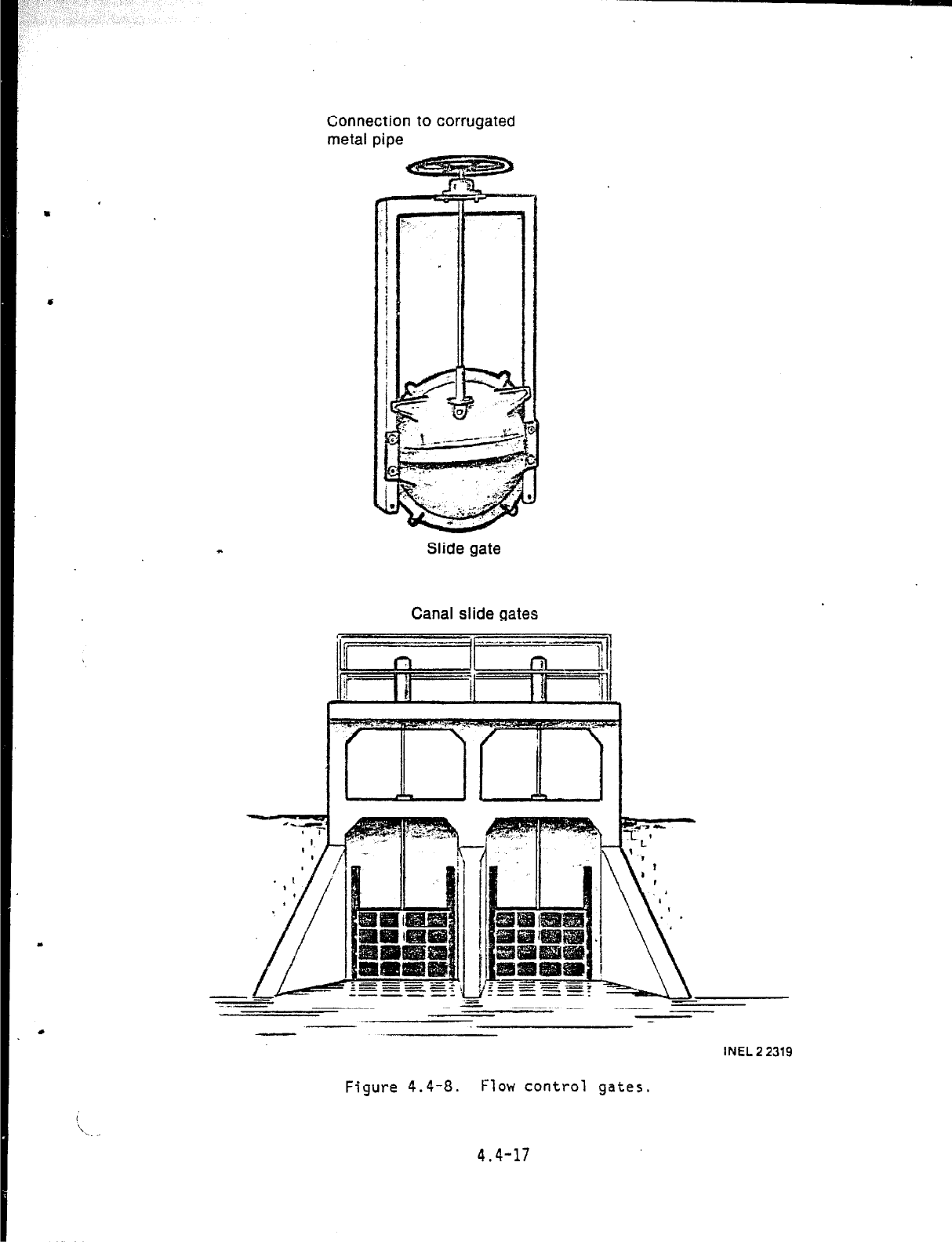
Connection to corrugated
metal pipe
Slide gate
Canal slide gates
--
_-.-
= .- .-- - _.--
-- ___.
INEL
2 2319
Figure 4.4-8.
Flow control gates.
4.4-17
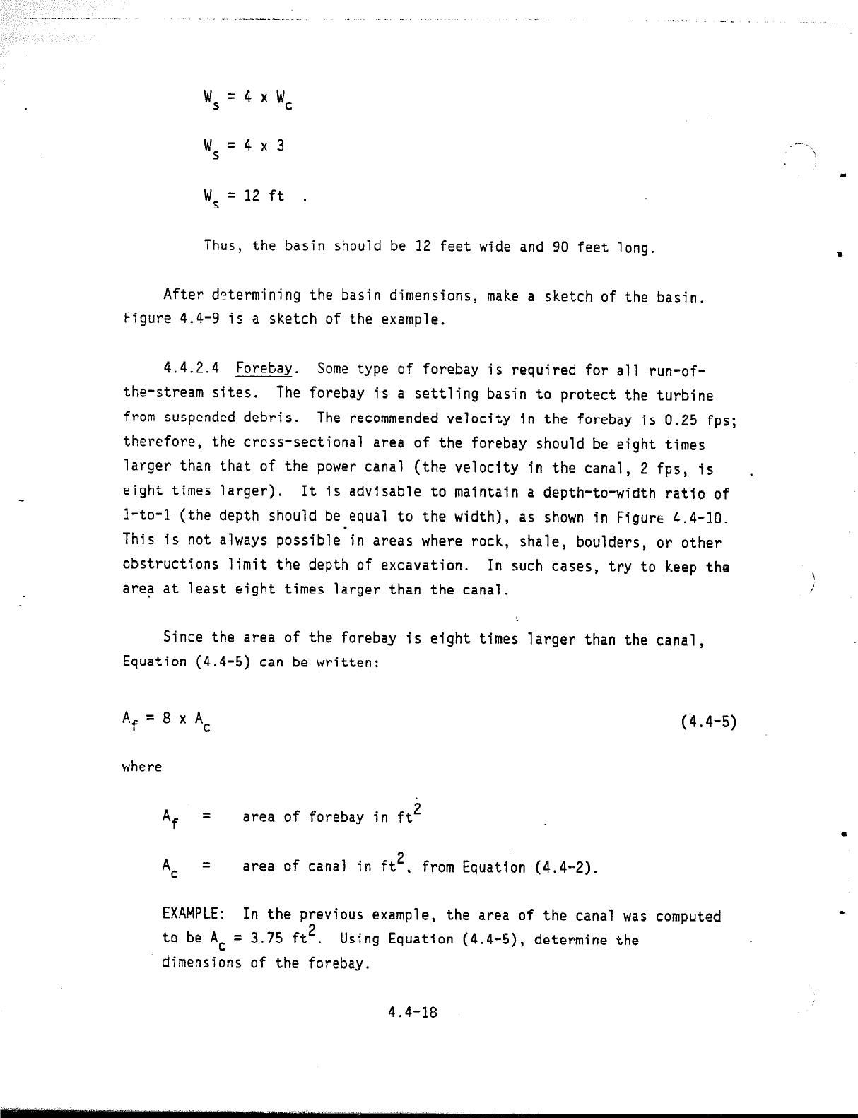
w
S
=4xwc
w
S
=4x3
wS
= 12 ft .
Thus, the basin should be 12 feet wide and 90 feet long.
After determining the basin dimensions, make a sketch of the basin.
Figure 4.4-9 is a sketch of the example.
4.4.2.4 Forebay.
Some type of forebay is required for all run-of-
the-stream sites.
The forebay is a settling basin to protect the turbine
from suspended debris.
The recommended velocity in the forebay is 0.25 fps;
therefore, the cross-sectional area of the forebay should be eight times
larger than that of the power canal (the velocity in the canal, 2 fps, is
.
eight times larger).
It is advisable to maintain a depth-to-width ratio of
l-to-l (the depth should be equal to the width), as shown in Figure 4.4-10.
This is not always possible'in areas where rock, shale, boulders, or other
obstructions limit the depth of excavation.
In such cases, try to keep the
area at least eight times larger than the canal.
Since the area of the forebay is eight times larger than the canal,
Equation (4.4-5) can be written:
A
’ f
=8xAc
where
(4.4-5)
Af =
area of forebay in ft2
AC =
area of canal in ft*,
from Equation (4.4-Z).
EXAMPLE:
In the previous example,
the area of the canal was computed
to be AC
= 3.75 ft?
Using Equation (4.4~5), determine the
dimensions of the forebay.
4.4-18
.
I I II I
I
I
_. _ _ _ ._ - . . .
1 .
_ _.-
. . -- -- i--c-
_- k4&~=12~.i
.- 1
__._ _ ..- - .-.- . .-
scl#
I
I...- -; -. -. . -. -, -- L - r..--+-y-
; -- : -4 .+
_ . .-. -
_
_ _ ._ _
-----.*...
._ ----
Figure 4.4-9.
Sketch of settling basin.
4.4-19
_^ . ..__ - ..-. _ - .-
Power canal
%
= 8 x 3.75
.
4.4-m
,
a
c
I’
i
does not have a square root (<) function, find the square (pro-
duct of a number multiplied by itself) that is closest to but
larger than Af.
For example, 5 x 5 = 25 and 6 x 6 = 36; there-
fore use 6 x 6.
Never use a width less than the canal width.
Assume in this example that you have a square root function on
the calculator.
The square root of 30 is 5.48. Therefore, %he
ideal forebay dimensions would be 5.5 feet by 5.5 feet.
Now assume that in the area where the forebay is to be placed the
maximum available depth is only 4 feet; find the new forebay
dimensions.
Since area equals width times depth and depth is
known, divide area by depth to get width:
Af
wf = q
where
Wf =
width of forebay in ft
Af
= area of forebay in ft*,
from Equation (4.4-6)
df
= depth of forebay in ft.
Therefore,
=30
wf 4
(4.4-6)
wf
=T.Sft .
The forebay should be oriented with respect to the penstock so that
the penstock can be kept as straight as possible.
In most cases where a
power canal is used, the penstbck takeoff will be placed at a 90 degree
angle to the canal on the downhill side of the forebay.
CL i’
4.4-21
The length of the forebay should be at least 45 feet to allow suffi-
cient time for the fine sand, etc. to settle.
Tf it is impractical to make
the forebay 45 feet long,
make the length as long as practical, and widen
the
forebay,
if possible.
The wider area will reduce the veloc<ty and
increase the settling time.
The forebay should also be equipped with a method for clean-out.
The
simplest method is to install 12-inch corrugated pipe through the downhill
berm.
The pipe should be placed on the bottom of the forebay. A slide
gate should be placed on the pipe to control flow.
A skimmer should be placed in the forebay ahead of the trashrack. The
skimmer should be angled to force the trash to the side of the forebay.
The skimmer is discussed in Subsection 4.4.2.7, Additional Hardware.
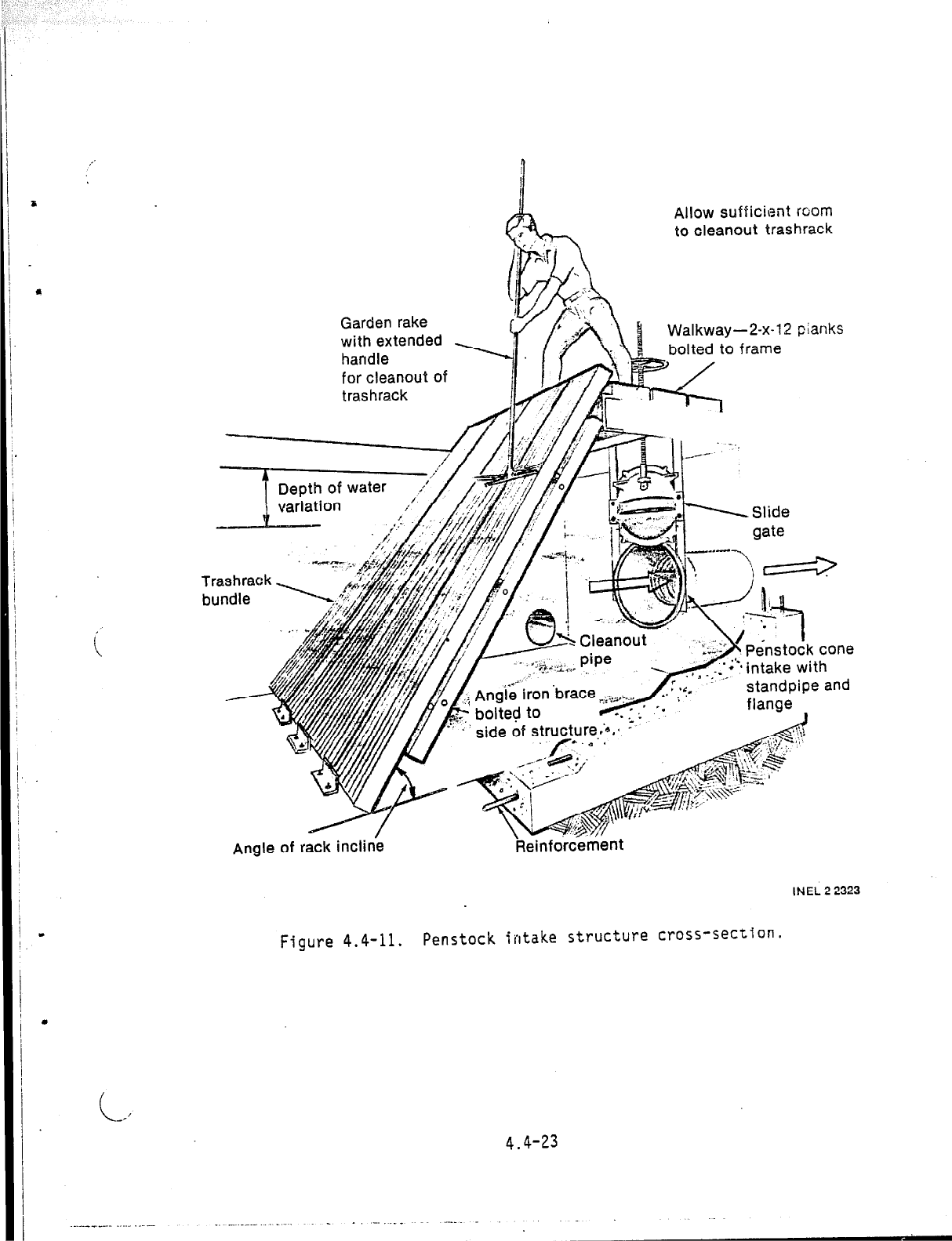
4.4.2.5 Trashrack--Although the trashrack is actually part of the
additional hardware, it is discussed separately at this point because the
trashrack must_ be sized before the penstock intake structure on which it is
mounted can be sized.
A trashrack is an essential element of any hydropower project. Micro-
hydropower. units in particular must be protected from trash carri'ed by the
*,
water. The rack must strain unwanted material from the water and yet hsvp
enough openings to allow the design flow to pass through without signifita!lt
loss of head.
The rack must aiso be strong enough to withstand water prci-
Sure forced‘agajnst it if the rack becomes completely clogged .+5th t.fas::.
A trashrack mounted on the penstock iiitake btructure is shown in
Figure.4.4-11.
*
I
-.
z
r)
.
!
Allow sufficient room
to cleanout trashrack
Garden rake
with extended
Walkway-2-x-12 pianks
bolted to frame
7
Depth of water
variation
/
i
Penstock cone
pr’” Y’..VI --
t.
. side of struIu.re.‘*.*. -
* ,!$-’
Angle of rack
incline
Reinforcement
INEL 2 2323
Figure 4.4-11.
Penstock intake structure cross-section.
4.4-23
9
The rack must be designed for easy, periodical cleaning without
interfering with the operation of the turbine.
Figure 4.4-12 and 4.4-13 are photos of two vertical slide-in racks,
set one behind the other.
Figure 4.4-14 is a photo of a barrel-type trash-
rack connected directly to the penstock intake.
The simplest trashrack is made of bundles that can be easily handled
by one person. A typical bundle can be fabricated from 2- to 3-inch flat
stock bars (strap metal), shown in Figure 4.4-15. Most racks should be
made with bars l/4-inch wide (very small ones can be made with l/g-inch
bars).
The bars can be fabricated into bundles typically 12 inches wide
with the bars placed vertical to the flow (see Figure 4.4-11). The length
can vary according to the site criteria (usually less than 10 feet for wsc
of handling). The clear space between the bars is the area that must be
designed to pass the design flow without causing significant head loss,
For microhydropower projects,
the spacing can range from l/2 inch to 1 inch
(see Figure 4.4-15). The smaller spacing is recommended for smaller turbine
units. Racks fabricated into bundles in thl's fashion can be removed indi-
vidually for repair, maintenance, etc.
Keep a spare!a
Because the design area is the clear'area between the bars, sizing the
trashrack is not as simple as finding the area of the power candl or tne
forebay.
The area of the bars must be added to the design area to obth<l:
the dimensions of the wetted area of the rack, the area suhner~~ri ;11.-!r .;
ilOWi31
design flow (see FIgtire 4.4-16).
Arid since the rack ::; st:i. r,t 4.: ,.
60 degrees, the area is based on that incline angle. Thp ctrnc invCI,:r..
are discussed in the paragraphs that follow.
--

, .; .
Figure 4.4-12. Vertical, .slide-in trashracks.
Figure 4.4-13, Vertical, slide-in trashracks.
4.4-25
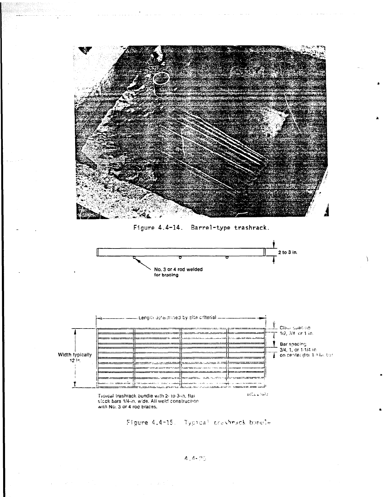
Figure 4.4-14. Barrel-type trashrack.
t
II
2 to 3 in.
D
cl
‘17
No. 3 or 4 rod welded
for bracing
e3 ty pi:* c-iterial ---
-- Cf
iyp~+l lrashrack imndie at?il 2. IO 3-o. tlai
s:ccI( bars Ill-tn. wide. All WC-I?! ;onslruclmn
wlh No. 3 or 4 rou bracas.
.
.