McKinney J.D., Warnick C.C. Microhydropower Handbook Volume 1
Подождите немного. Документ загружается.

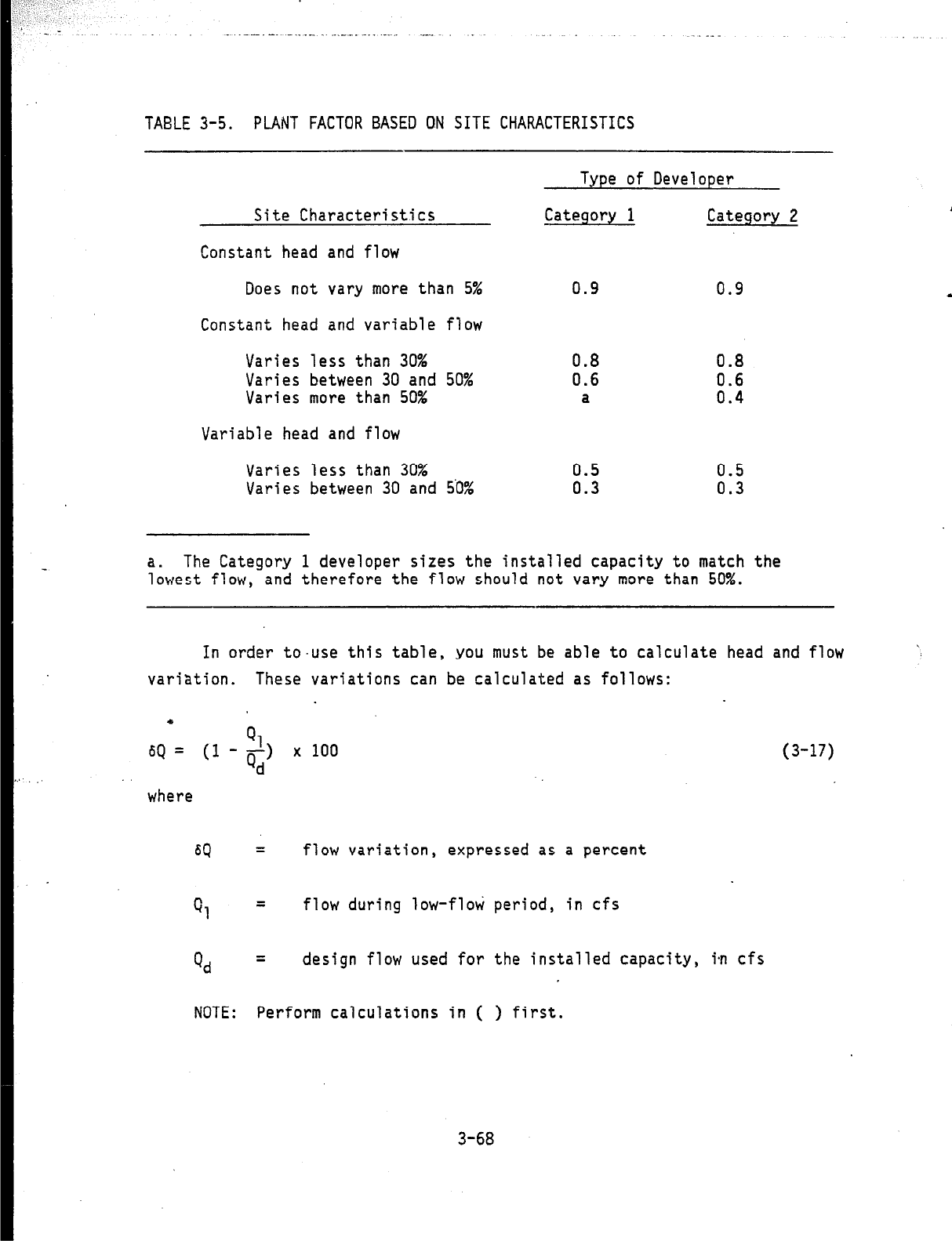
TABLE 3-5.
PLANT FACTOR BASED ON SITE CHARACTERISTICS
Type of Developer
Site Characteristics
Category 1
Category 2
Constant head and flow
Does not vary more than 5%
0.9 0.9
Constant head and variable flow
Varies less than 30%
0.8
0.8
Varies between 30 and 50%
0.6
Varies more than 50%
a
8::
Variable head and flow
Varies less than 30%
Varies between 30 and 5'0%
0.5
E 0.3
a. The Category 1 developer sizes the installed capacity to match the
lowest flow, and therefore the flow should not vary more than 50%.
In order to-use this table, you must be able to calculate head and flow
variation.
These variations can be calculated as follows:
6Q =
Ql
(1 ---I
Qd
x 100
where
SQ =
flow variation,
expressed as a percent
0, =
flow during low-flati period, in cfs
Q, =
design flow used for the installed capacity, in cfs
(3-17)
NOTE:
Perform calculations in ( ) first.
3-68
hl
6h= (I+ x100
(3-18)
h
-where
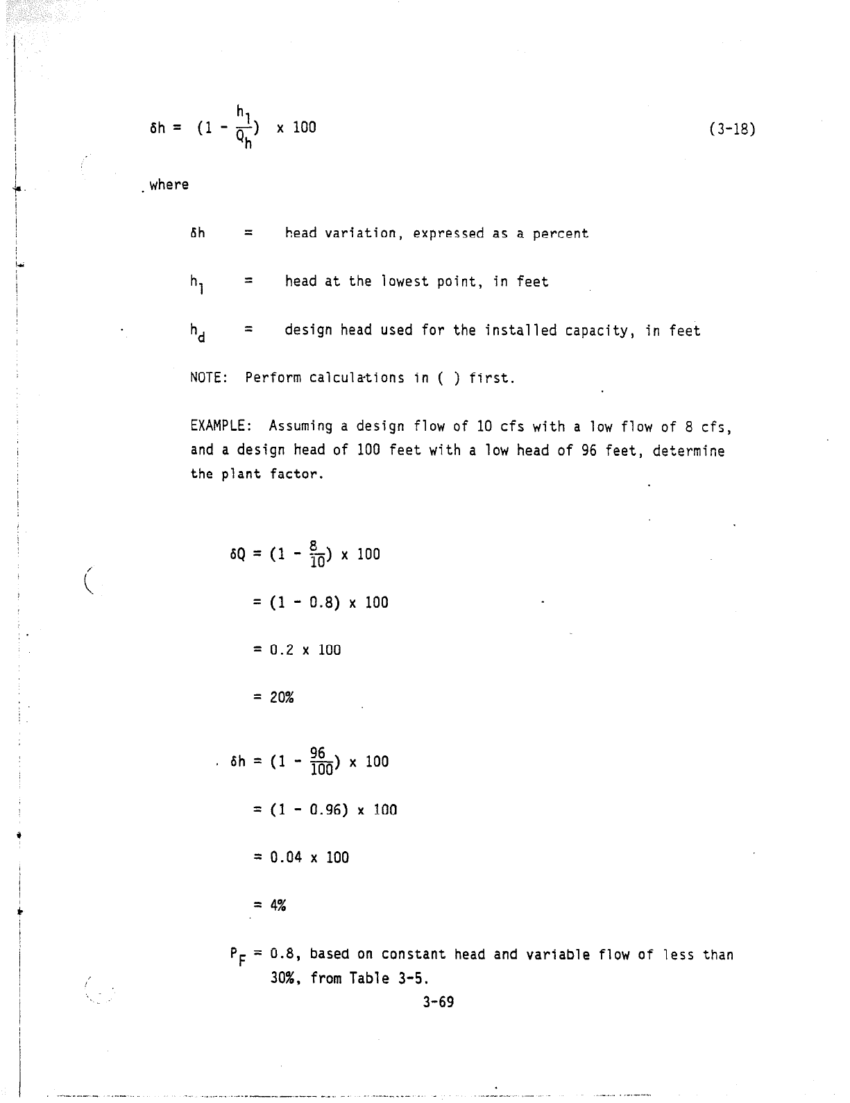
6h =
head variation, expressed as a percent
h, =
head at the lowest point, in feet
hd = design head used for the installed capacity, in feet
NOTE:
Perform calculations in ( ) first.
EXAMPLE: Assuming a design flow of 10 cfs with a low flow of 8 cf;,
and a design head of 100 feet with a low head of 96 feet, determine
the plant factor.
SQ = (1
i
- $) x 100
/
= (1 - 0.8) x 100
= 0.2 x 100
= 20%
e 6h=(l
- g-, x 100
= (1 - 0.96) x 100
= 0.04 x 100
= 4%
/
,
'I
pF
= 0.8, based on constant head and variable flow of less than
30%, from Table 3-5.
3-69
_.~(_____ ,..- -_ .,.___. ..______.____ -__ _.
-.-_. __._._ . _ ..---.-_ ..-
.__~_ .._. ---
I
4. DESIGN, EQUIPMENT, AND SAFETY REQUIREMENTS
I
\
In this section, the
following subjects are addressed.
1 ” _
!
e
0
i-
0
0
0
Designing penstock and valves
0
0
0
General discussion on turbines
Contacting turbine generator manufacturers and suppliers
Making a go/no-go decision and establishing design criteria
Designing an intake system
Designing a powerhouse
Designing a tailrace
Selecting a generator and designing electrical equipment
Designing a drive system and speed increasers.
The developer who has followed the instructions in the previous
sections has accomplished the following:
e Has identified with the appropriate developer category.
ing power for persona
1
Desires to be energy independent produc
needs.
Desires to produce the most power for the dollar invested,
0
Has identified the type of source.
Run-of-the-stream
Manmade.
4-l
I
--..
_
___
_.
_.
_
_.__-..__
__
-.-_
-..
_____
_
_
__.
_
_
a
Has selected preliminary design head, or knows the head variation.
a
Has measured flow and has selected 3 preliminary design flow.
l
I
Has determined the power requirements.
0
Has preliminary selection for location of intake structure and
power house.
0
Has measured length of penstock and transmission lines based on
preliminary locations.
With this information, the next step is to contact various manufac-
turers and request additional information.
A general discussion on turbines
is provided next to aid in selecting the manufacturer whose turbines have
the best potential of meetjng the site criteria.
l
4-2
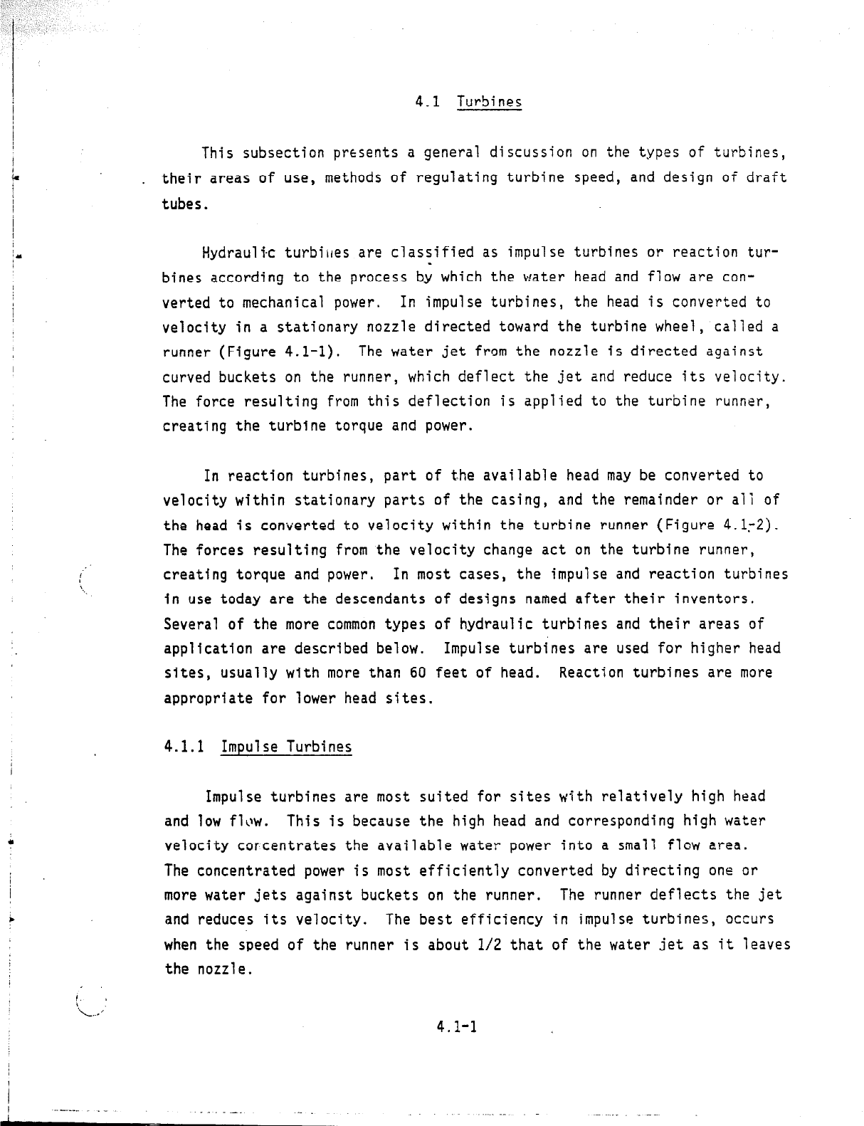
4.1 Turbines
This subsection presents a general discussion on the types of turbines,
. their areas of use, methods of regulating turbine speed, and design of draft
tubes.
Hydraulic turbiires are classified as impulse turbines or reaction tur-
bines according to the process by which the water head and flow are con-
verted to mechanical power.
In impulse turbines, the head is converted to
velocity in a stationary nozzle directed toward the turbine wheel, called a
runner (Figure 4.1-l).
The water jet from the nozzle is directed against
curved buckets on the runner, which deflect the jet and reduce its velocity.
The force resulting from this deflection is applied to the turbine runner,
creating the turbine torque and power.
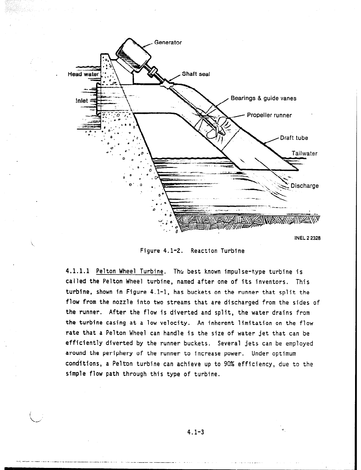
In reaction turbines, part of the available head may be converted to
velocity within stationary parts of the casing, and the remainder or all of
the head is converted to velocity within the turbine runner (Figure 4.1.-2).
The forces resulting from the velocity change act on the turbine runner,
creating torque and power.
In most cases, the impulse and reaction turbines
in use today are the descendants of designs named after their inventors.
Several of the more common types of hydraulic turbines and their areas of
application are described below.
Impulse turbines are used for higher head
sites, usually with more than 60 feet of head. Reaction turbines are more
appropriate for lower head sites.
4.1.1 Impulse Turbines
Impulse turbines are most suited for sites with relatively high head
and low flilw. This is because the high head and corresponding high water
velocity corcentrates the available water power into a small flow area.
The concentrated power is most efficiently converted by directing one or
more water jets against buckets on the runner.
The runner deflects the jet
and reduces its velocity. The best efficiency in impulse turbines, occurs
when the speed of the runner is about l/2 that of the water jet as it leaves
the nozzle.
4.1-1
. .-.
-
Generator
\
‘_
L
.
INEL 2 2331
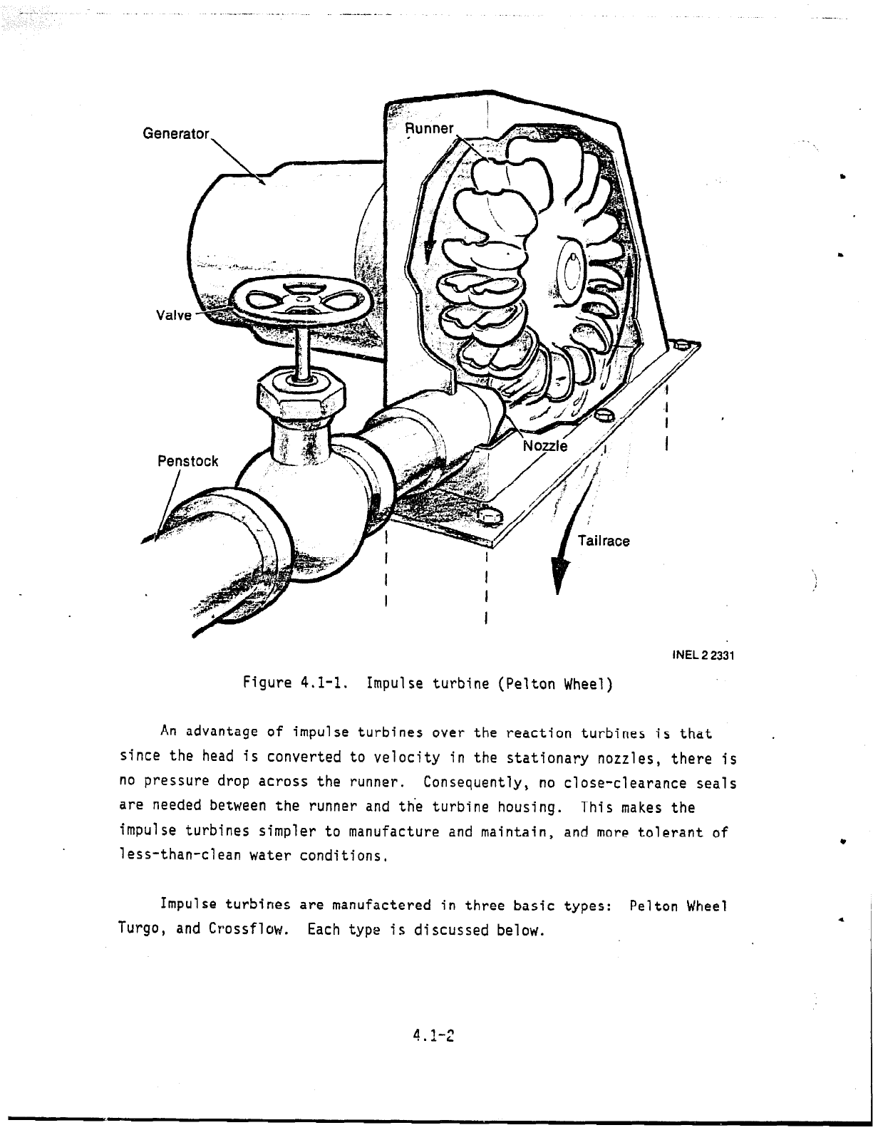
Figure 4.1-1.
Impulse turbine (Pelton Wheel)
An advantage of impulse turbines over the reaction turbines is that
.
since the head is converted to velocity in the stationary nozzles, there is
no pressure drop across the runner.
Consequently, no close-clearance seals
are needed between the runner and the turbine housing.
This makes the
impulse turbines simpler to manufacture and maintain, and more tolerant of
less-than-clean water conditions,
Impulse turbines are manufactered in three basic types: Pelton Wheel
Turgo, and Crossflow.
Each type is discussed below.
4.1-Z
&Generator
!n
\.
, Bearings & guide vanes
\
.
ri
*
Q-
Propeller runner
&
"-
-x
' .o
-. . 'C
.‘li. /
* . .
Draft tube
Tailwater
INEL 2 2328
Figure 4.1-2.
Reaction Turbine
4.1.1.1 Pelton Wheel Turbine.
Thl- best known impulse-type turbine is
ca'lled the Pelton Wheel turbine, named after one of its inventors.
This
turbine, shown in Figure 4.1-1, has buckets on the runner that split the
flow from the nozzle into two streams that are discharged from the sides of
the runner.
After the flow is diverted and split, the water drains from
the turbine casing at a low velocity.
An inherent limitation on the flow
rate that a Pelton Wheel can handle is the size of water jet that can be
efficiently diverted by the runner buckets.
Several jets can be employed
around the periphery of the runner to increase power.
Under optimum
conditions, a Pelton turbine can achieve up to 90% efficiency, due to the
simple flow path through this type of turbine.
!
i,-’
4.1-3
-.- -- ---_ .----.-.l_-_-_-.-- __.-._ - _..- -_ _.
-, ._ .___ ------- -.-.
-
_. _ .__
. - _ .-
__ .- . .-
~-
Application Guidelines--Pelton Turbines:
tlead:
75 feet of head and up
Flow:
Varies, but lowest of all turbines relative to head
cost:
$300 to $500/kW on suitable site. Cost per unit of
output will decline as head increases.
Peltons are
uneconomic at low heads because limited water handling
restricts output.
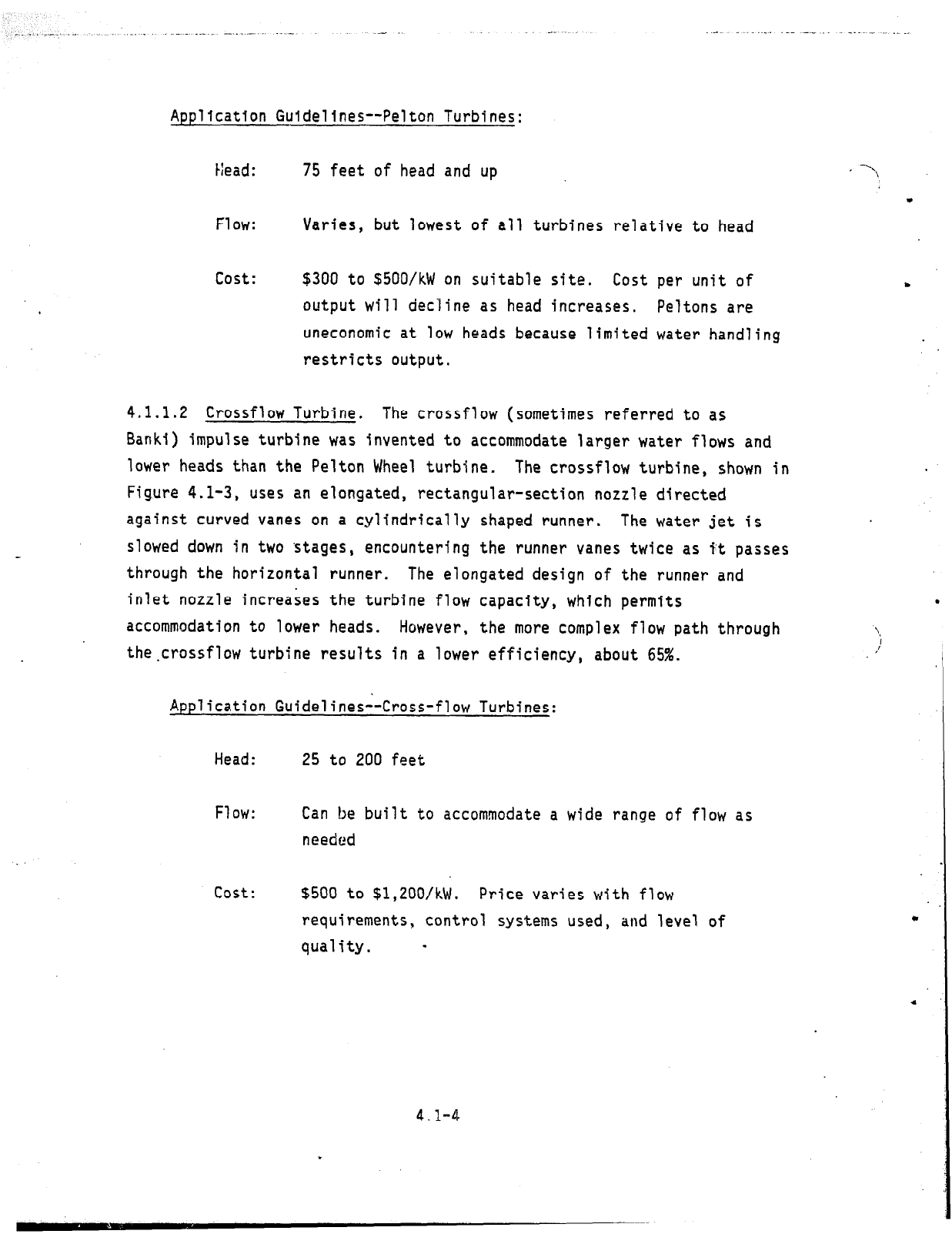
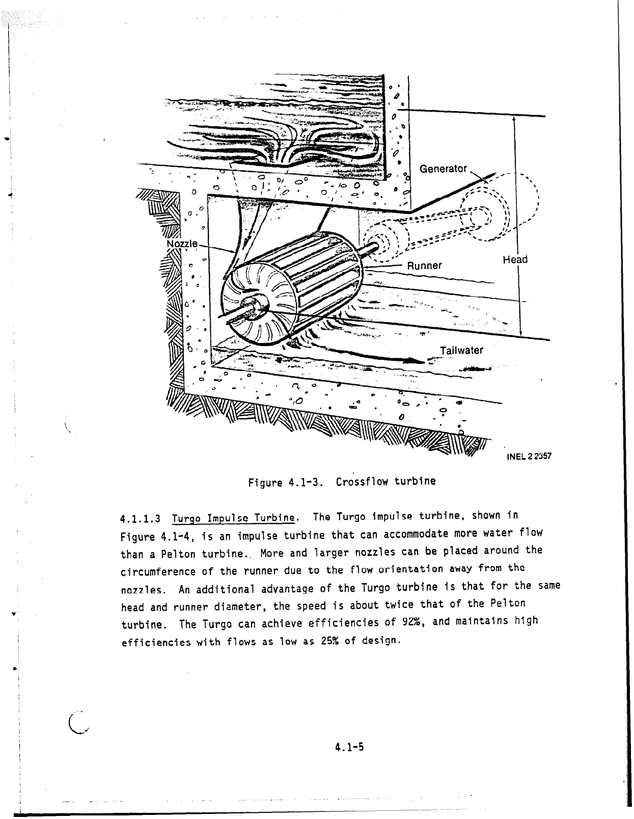
4.1.1.2 Crossflow Turbine.
The crossflow (sometimes referred to as
Banki) impulse turbine was invented to accommodate larger water flows and
lower heads than the Pelton Wheel turbine.
The crossflow turbine, shown in
Figure 4.1-3, uses an elongated, rectangular-section nozzle directed
against curved vanes on a cylindrically shaped runner.
The water jet is
slowed down in two 'stages,
encountering the runner vanes twice as it passes
through the horizontal runner.
The elongated design of the runner and
inlet nozzle increases the turbine flow capacity, which permits
accommodation to lower heads.
However, the more complex flow path through
the.crossflow turbine results in a lower efficiency, about 65%.
Application Guidelines--Cross-flow Turbines:
Head:
25 to 200 feet
Flow:
Can be built to accommodate a wide range of flow as
needed
cost:
$500 to $1,20O/kW. Price varies with flow
requirements, control systems used, and level of
quality. -
.
i
/
I
4.1-4
,
I- 2
Generator,
INEL 2 2357
Figure 4.1-3.
Crossflow turbine
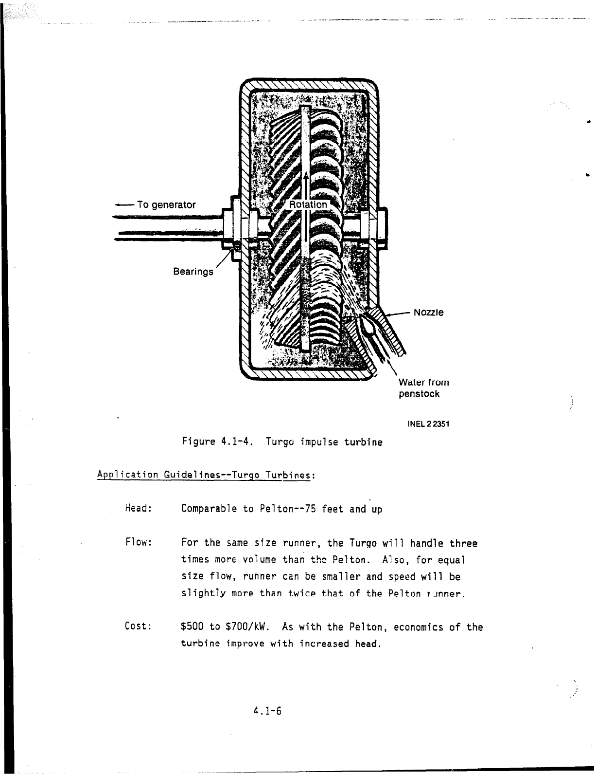
4.1.1.3 Turgo Impulse Turbine. The Turgo impulse turbine, shown in
Figure 4.1-4, is an impulse turbine that can accommodate more water flow
than a Pelton turbine., More and larger nozzles can be placed around the
circumference of the runner due to the flow orientation away from the
nozzles.
An additional advantage of the Turgo turbine is that for the same
head and runner diameter, the speed is about twice that of the Pelton
turbine.
The Turgo can achieve efficiencies of 92%, and maintains high
efficiencies with flows as low as 25% of design.
: -
c
i
4.1-S
._ .-
_...
penstock
INEL 2 2351
Figure 4.1-4.
Turgo impulse turbine
Application Guidelines--Turgo Turbines:
Head:
Comparable to Pelton-- feet and up
Flow:
For the same size runner, the Turgo will handle three
times more volume thai the Pelton.
Also, for equal
size flow, runner can be smaller and speed will be
slightly more than twice that of the Pelton tanner.
cost:
$500 to $700/kW.
As with the Pelton, economics of the
turbine improve with increased head.
4.1-6
‘.
Y
.