Mason C. Russell. The art and science of protective relaying
Подождите немного. Документ загружается.

330 LINE PROTECTION WITH PILOT RELAYS
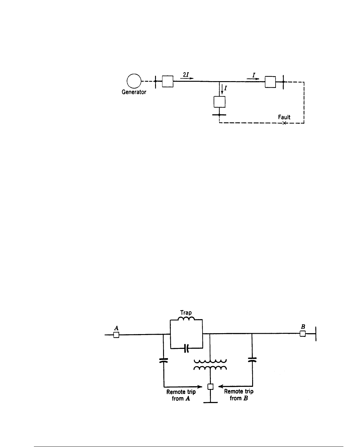
Another way of avoiding high pickup of the tripping fault detectors for situations like
Fig. 4 is to use directional relays to control tripping at places like terminal C. However, this
kind of solution will not work for the situation illustrated by Fig. 5 where the same problem
exists, but at a terminal where the large current is flowing in the tripping direction.
At a load terminal, back of which there is no source of generation, and where there is no
power-transformer neutral grounding on the high-voltage side, blocking-terminal
equipment consisting of instantaneous overcurrent relays and a carrier-current transmitter
can be used to block tripping at the main terminals for faults in the load circuits. Of
course, this is necessary only if the main-terminal equipment is sensitive enough to operate
for low-voltage faults at a load terminal. The phase-sequence network, comparer, etc., that
are used in the equipment at the main terminals are not necessary, since no tripping
function is provided at the blocking terminal. To block tripping at the main terminals, the
overcurrent relays simply turn on carrier that is transmitted continuously and not every
other half cycle. The blocking relays should be energized from CT’s on the high-voltage
side of the load-terminal power-transformer bank so that tripping will be blocked on
magnetizing-current inrush. If the power transformer is wye-delta and grounded on the
wye side, a ground overcurrent relay would be required to shut off carrier for ground faults
on the high-voltage side.
If tripping at a blocking terminal is required to avoid damage to large motors when
automatic reclosing is used at the main terminals, such tripping will probably have to be
provided by local underfrequency relays. Remote tripping by carrier current over the
protected line from the main terminals to such a load terminal could not be assured unless
the tripping of the main terminals will extinguish an arcing phase-to-ground fault that
might be on the phase to which the carrier-current equipment is coupled. Synchronous
motors, acting as generators, might be able to generate sufficient voltage to maintain an
arc through the capacitance to ground of the unfaulted conductors. Some users have
installed equipment that relies on transmitting sufficient carrier current for remote
Fig. 5. A situation in which directional relaying will not prevent reduced sensitivity.
Fig. 6.. Method of avoiding interference by a fault with remote tripping.

LINE PROTECTION WITH PILOT RELAYS 331
tripping past an arcing ground fault on the coupling phase, but such operation cannot be
assured in general. One solution is to use phase-to-phase coupling for the remote-trip
signal, or to transmit this signal over another line section if the lines are parallel. Another
solution that has been used is shown in Fig. 6; no matter where the fault is, one main
terminal or the other can cause remote tripping.
Remote tripping from power-transformer differential relays at a load terminal to the
breakers at the main terminals can be done over the carrier-current channel.
5
Whenever
remote tripping for transformer faults is undertaken, a line trap should be inserted in the
coupling phase between the coupling capacitor and the power transformer, so that power-
transformer faults to ground on the coupling phase cannot short-circuit the
carrier-current-transmitter output.
A multiterminal line can sometimes be well protected against ground faults even though
adequate phase-fault protection is impossible. This is because line taps are usually made
through delta-wye power-transformer banks, which are open circuits so far as zero-phase-
sequence currents on the high-voltage side are concerned. Therefore, if only ground
relaying equipment is used and arranged to receive only the CT neutral current, such a
multi terminal line may be treated as a two-terminal line.
BACK-UP PROTECTION
Phase-comparison relaying does not provide back-up protection. This should be provided
by phase distance relays and either overcurrent or distance ground relays. When phase-
comparison relaying is applied to an existing line, it is often the practice to use the existing
relaying equipment for back-up protection.
Conventional back-up relaying will be inadequate when intermediate current sources
supply so much current to a fault that the fault is put beyond the reach of the back-up
relays. Such a problem and its solution are described in Chapter 14 under the heading
“The Effect of Intermediate Current Sources on Distance-Relay Operation.” In such a
situation it will be at the discretion of the user whether, in addition to the special back-up
equipment, conventional back-up equipment is also applied to provide primary relaying
while the phase-comparison equipment is being maintained or repaired.
DIRECTIONAL COMPARISON
Directional-comparison relaying is the most widely applicable type, and therefore it lends
itself best to standardization programs. The only circumstance in which directional
comparison is not applicable is when there is sufficient mutual induction with another line
and when directional ground relays are used instead of ground distance relays; this is
treated at greater length later under “Combined Phase and Directional Comparison.”
In general, apart from considerations of carrier-current attenuation, the application of
directional-comparison relaying is largely a matter of applying phase distance and
directional-ground or ground distance relays. This is because, as mentioned in Chapter 6,
conventional equipment uses certain units in common for carrier-current-pilot primary
relaying and for back-up relaying. In fact, if a line is now protected by phase distance relays
and ground overcurrent or distance relays, one may merely need to add some
332 LINE PROTECTION WITH PILOT RELAYS
supplementary relays plus the carrier-current equipment to apply directional-comparison
carrier-current-pilot relaying; the supplementary relays and carrier-current equipment
provide the blocking function while the existing relays provide the tripping function. Of
course, completely separate relaying could be used, but it would be more expensive.
RELATION BETWEEN SENSITIVITIES OF TRIPPING AND
BLOCKING UNITS FOR TWO-TERMINAL LINES
The principal application procedure is to be sure that the correct relations are obtained
between the operating ranges of the blocking and tripping units. This is seldom a problem
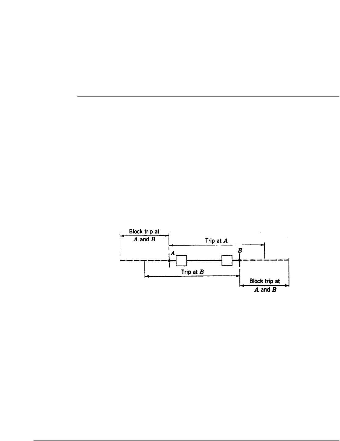
for a two-terminal line. Figure 7 shows the relative operating ranges of the blocking and
tripping units at both ends of a two-terminal line for, say, phase faults. The significant
observation is that, for external faults beyond either end of the line, the blocking units
must reach out farther than the tripping units to be certain that, if there is any tendency
to trip, it will surely be blocked. The tripping range for phase faults will be the operating
range of the second- or third-zone distance-relay units, depending on the type of
equipment.
The only time there is any problem adjusting the blocking units is when their range has to
be so great that they might operate on load current, or that having operated for a fault they
might not reset on load current. In such situations, it becomes necessary to use additional
units called “blinders.” These units are angle-impedance distance-relay units, one of which
would be used with each blocking relay. The contacts of the two relays of each group would
be connected in parallel so that both would have to open to start carrier. Figure 8 shows
the operating characteristics of both relays and the point representing the load condition
that makes blinders necessary. The resulting blocking region is shown cross-hatched.
Blinders with impedance-type distance relays are shown because this type of relay is the
most likely to require blinders for this purpose.
Incidentally, such blinders have been used also to prevent tripping on load current where
distance relays have been applied to unusually long lines.
When low-tension voltage is used, transformer-drop compensation is not so necessary as
when distance relays are used alone. The only time that transformer-drop compensation
would be beneficial would be when the carrier-current equipment is out of service and
complete reliance for protection is being placed on the distance relays. Such circumstances
occupy so little of the total time that the additional complications of transformer-drop
compensation are not justified.
Fig. 7. Relative operating ranges of directional-comparison blocking and tripping units.

LINE PROTECTION WITH PILOT RELAYS 333
The problem of obtaining the correct relations between the tripping and blocking units for
multiterminal-line applications, along with other related problems, is treated next.
THE PROTECTION OF MULTITERMINAL LINES
Directional-comparison relaying is applicable to any multiterminal line. However, under
some circumstances proper operation will not be obtained without a very careful choice of
the type of equipment and of the blocking- and tripping-relay adjustments.
4,15
And
sometimes simultaneous high-speed tripping at all terminals will not be obtained.
Therefore, one should be familiar with these circumstances so as to be able to avoid them,
ifpossible,intheearlystagesof system planning. These circumstances will now be described.
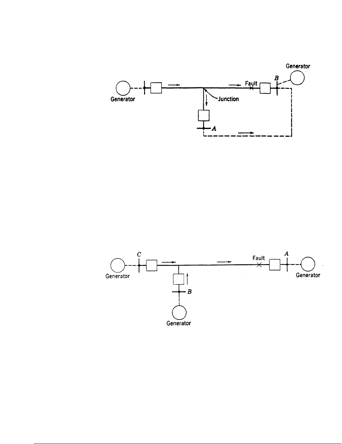
Current Flow Out of One Terminal for an Internal Fault. In Fig. 9, directional-comparison
relaying cannot trip for an internal fault if the current flowing out of the line at A is higher
than the blocking-relay pickup there. This situation may exist for phase faults or ground
faults or both. If it is not permissible to raise the blocking relay pickup so as to avoid this
situation, tripping must wait until the back-up relays at B trip their breaker, after which
high-speed tripping can occur at the other two terminals.. For phase faults, the distance
relays at B will operate at high speed, and sequential high-speed tripping of all other
terminals can follow if there is enough fault current, and if other features of the equipment
do not introduce time delay. For ground faults, the tripping of breaker B will be delayed
slightly unless ground distance or instantaneous overcurrent ground relays are used.
Remote tripping from breaker B to the other terminals by means of carrier current over
the protected line is not a reliable way to avoid sequential tripping, unless this type of
difficulty occurs only for faults not involving ground. Or, if it occurs only for ground faults,
phase-to-phase coupling could be used. Although some users are relying on getting
sufficient remote-tripping signal past a phase-to-ground fault on the coupling phase,
satisfactory results cannot be assured in general. Occasionally, another line section can be
used for carrying the remote-tripping signal. Obviously, remote tripping would be practical
if microwave were used instead of carrier current.
Fig. 8. A blinder to prevent blocking on load current.
334 LINE PROTECTION WITH PILOT RELAYS
Insufficient Current for Tripping. Apart from there being too small a source of short-circuit
current back of a terminal, other circumstances can make the current so low–or the
apparent impedance to the fault so high–as to prevent or at least to delay tripping.
For the circumstance of Fig. 9, if the fault is closer to the junction, the current at A will be:
(1) in the blocking direction but too low to operate a blocking relay, (2) zero, or (3) in the
tripping direction but too low to operate a tripping relay. For any of these, tripping at
the other terminals would not be blocked, but tripping at A would have to wait until the
breakers at B had tripped, assuming that there would then be a redistribution of enough
fault current at A to cause tripping there.
Another circumstance in which the fault current may be too low is shown in Fig. 10. Here,
the intermediate current, or “mutual impedance effect,” as it is sometimes called, may
prevent tripping at both B and C. Furthermore, the tripping of the breakers at A may not
relieve the inability to trip at breakers B and C, so that even sequential tripping may not be
possible.
As stated before, remote tripping is not a complete solution to the problem. Instantaneous
undervoltage carrier-starting or tripping relays are a solution if their adjustments can be
coordinated with those of the other relays.
2
Shortcomings of Non-Directional Blocking Relays. Some directional-comparison equipments use
non-directional overcurrent or impedance relays to start carrier. Occasionally, such
equipments block tripping for an internal fault because the current or apparent
impedance falls between the pickup of the blocking and tripping relays at the same
terminal. Basically, the pickup adjustment of the blocking relays at a given terminal has to
coordinate with the pickup adjustments of tripping relays at the other terminals. However,
when non-directional blocking relays are used, coordination must also be obtained
between the pickup adjustments of blocking and tripping relays at the same terminal. Such
Fig. 9. Situation in which directional comparison blocks tripping for an internal fault.
Fig. 10. Insufficient current for tripping.
LINE PROTECTION WITH PILOT RELAYS 335
a circumstance can exist when there is insufficient current or too high an apparent
impedance to cause tripping at a given terminal until after another terminal has tripped,
as in one of the preceding cases. However, if a blocking relay at the given terminal should
operate, it would block tripping at the other terminals; this situation would persist until a
back-up relay operated to cause tripping at another terminal that would permit the given
tripping relay to operate. The best solution to this problem is directional blocking relays.
Miscellaneous Problems of Coordinating Blocking and Tripping Sensitivities. It is necessary that
the coordination between blocking and tripping sensitivities be carefully analyzed not only
for multiterminal operation but also when a line is operated with one or more terminals
open. Owing to elimination of intermediate current sources, such operation may increase
the reach of the tripping relays at one terminal; one must be sure that these relays do not
outreach the blocking relays at another terminal.
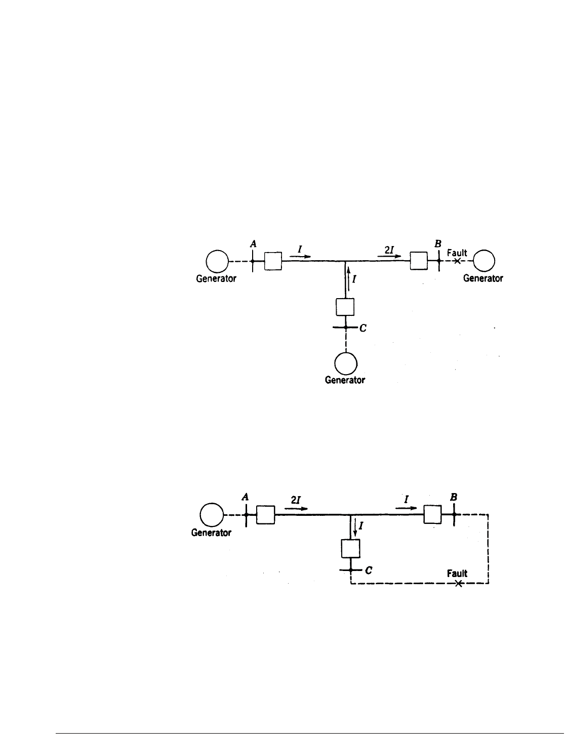
Figures 11 and 12 show two extreme operating conditions for a three-terminal line, so far
as the relative blocking and tripping sensitivities are concerned. For Fig. 11, the blocking
relays at terminal B get twice as much current as the tripping relays at A or C; for Fig 12,
the blocking relays at B and C get only half as much current as the tripping relays at A.
Even greater extremes could exist for a line with more than three terminals.
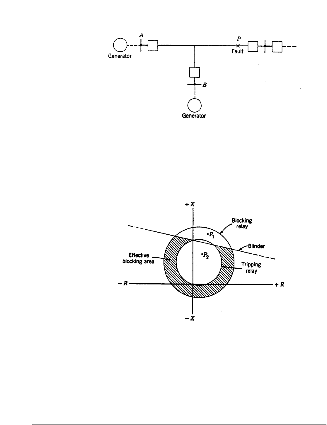
Need for a Blinder on the Loss-of-Synchronism Blocking Relay. If the phase tripping relays at
terminal A of Fig. 13 cannot operate to trip until after terminal B has tripped for the fault
location P, a supplementary angle-impedance relay should be used to provide a “blinder”
for the loss-of-synchronism blocking relay. The need for this blinder is shown in Fig. 14.
The point P
1
represents the way the fault first appears to the tripping and blocking relays
at A, and the point P
2
represents the appearance of the fault after B has tripped.
Fig. 11. Directional-comparison blocking relays get twice as much current as tripping relays.
Fig. 12. Directional-comparison tripping relays get twice as much current as blocking relays.
336 LINE PROTECTION WITH PILOT RELAYS
It will be noted that this sequence will establish local blocking at A by the loss-of-
synchronism relay, and, consequently, that tripping there can only occur in third-zone
time.
Figure 14 shows how the blinder characteristic modifies the operating characteristic of the
blocking relay so that when the fault first occurs it will not fulfill the requirement for the
second step in the sequence of operations necessary to set up loss-of-synchronism blocking.
The effective blocking area is shown cross-hatched.
Blocking-Terminal Equipment at Load Terminals. At terminals behind which there is no source
of generation, only blocking equipment may be required. Such equipment is required if
the high-speed relays at any of the main terminals are sensitive enough to operate for a
low-voltage fault at such a load terminal. The blocking-terminal equipment consists of
instantaneous overcurrent relays, energized from CT’s on the high-voltage side of the
power-transformer bank, and carrier-current transmitting and receiving equipment. The
overcurrent relays start the transmission of carrier current to block tripping at the main
terminals for low-voltage faults at the load terminal or for magnetizing-current inrush to
the load-terminal power-transformer bank.
Fig. 13. Situation in which the loss-of-synchronism blocking relay will block tripping
for an internal fault.
Fig. 14. R-X diagram of the conditions of Fig. 13.
LINE PROTECTION WITH PILOT RELAYS 337
As described for phase-comparison relaying, remote tripping from a blocking-terminal
power-transformer differential relay to the breakers at the main terminals can be
accomplished over the carrier-current channel.
5
EFFECT OF TRANSIENTS
Directional-comparison relaying using high-speed ground relays energized from zero-
phase-sequence quantities is exposed to more possibilities of misoperation than is
phase-comparison relaying. Reference 6 describes a host of things that tend to fool such
ground relays. However, conventional directional-comparison-relaying equipments have
certain features, developed as a result of experience, that minimize any tendency toward
misoperation. Such features are: (1) limited sensitivity, (2) slight time delay in auxiliary
relays, and (3) “transient blocking” or the prolongation of a carrier-current blocking signal
for several cycles after a relay operates to try to shut it off. Also, induction-type directional
units in both the carrier-starting and the tripping functions make the units unresponsive
to transients in only one of the operating quantities.
Ground distance relays, that respond to positive-phase-sequence impedance, for
controlling carrier-current transmission and for tripping eliminate the problem of
misoperation on transients.
COMBINED PHASE AND DIRECTIONAL COMPARISON
Directional-comparison relaying using directional-ground relays may operate undesirably
if there is sufficient mutual induction with a neighboring power circuit.
6
The directional-
ground relays misoperate because their polarization is adversely affected, as will be
described later. This would seem to indicate the desirability of phase-comparison relaying
which would be unaffected by mutual induction. If phase comparison was completely
applicable, it would be a good solution. However, occasionally it does not have sufficient
sensitivity for phase faults, although it would be entirely satisfactory for ground faults.
Under these circumstances combined phase- and directional-comparison relaying is
chosen. The directional-comparison principle is used for phase faults and the phase-
comparison principle is used for ground faults. Because the carrier-current transmitter
and receiver are employed in common, the equipment is only a little more expensive than
directional comparison alone. Incidentally, the phase-comparison ground-fault equipment
is less affected by most of the transient conditions that affect directional-ground relays.
Fig. 15. Illustrating the cause of undesired directional-ground-relay operation
resulting from mutual induction.
338 LINE PROTECTION WITH PILOT RELAYS
If ground distance relays were used in the directional-comparison equipment instead of
directional-ground relays, it would be unnecessary to resort to combined phase- and
directional-comparison equipment. However, it would be somewhat more expensive, but it
would provide better back-up protection.
THE EFFECT OF MUTUAL INDUCTION ON
DIRECTIONAL-GROUND RELAYS
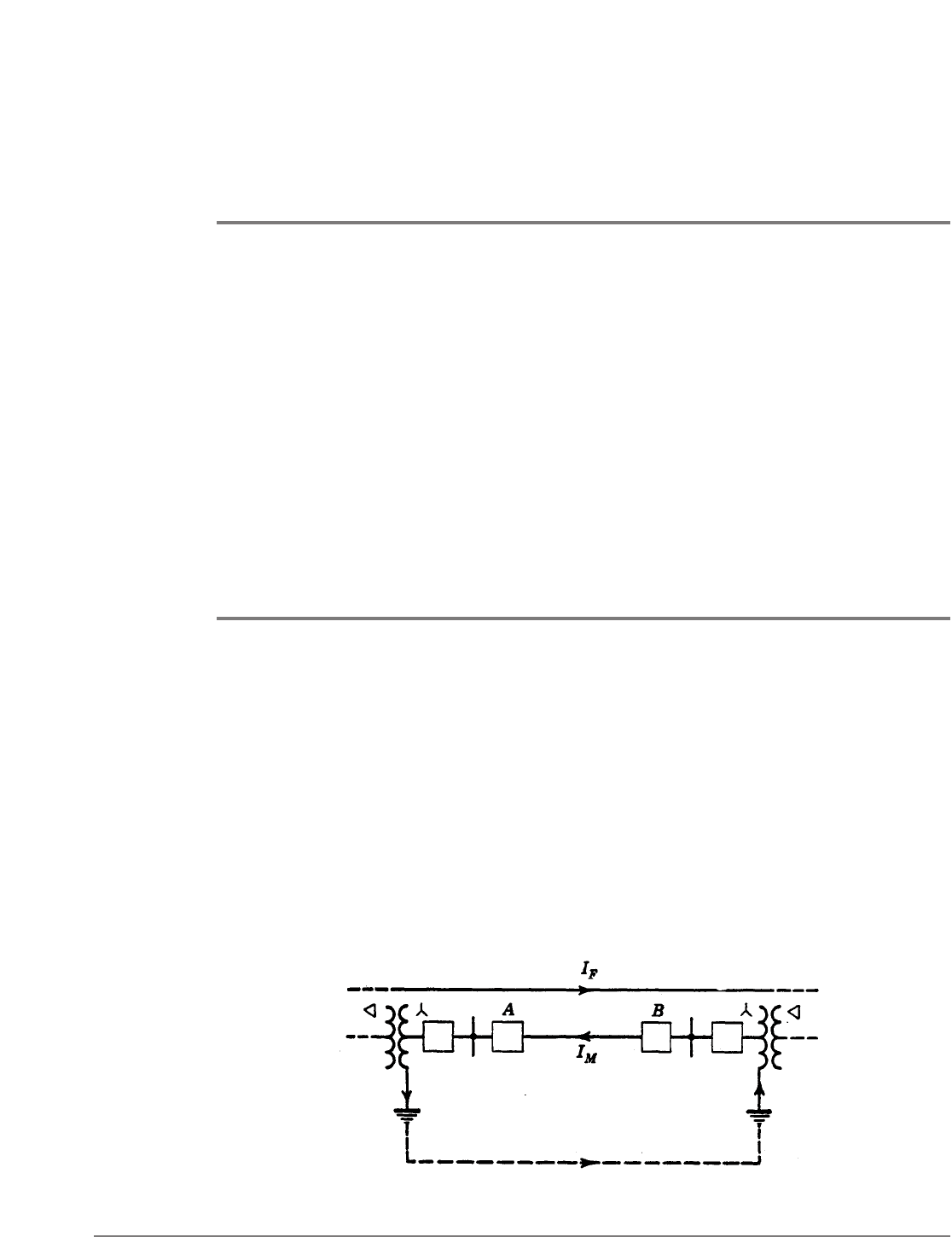
Figure 15 illustrates the fundamental principle involved in the undesired operation of
directional-ground relays. As shown in Fig. 15, fault current I
F
flowing in a nearby line
causes current I
M
to flow by mutual induction in the line under consideration. The
induced current circulates through grounded-neutral power-transformer banks at the ends
of the line and the earth, as shown. The difficulty is that directional-ground relays at both
ends of the line tend to operate under such circumstances. At location B, the polarizing
current flows from the ground into the neutral of the grounded power transformer and
from the bus into the line; this is the same as for a ground fault on the line for which
directional-ground relays are intended to operate. The fact that, at end A, both the
currents are reversed with respect to the directions at B also produces a tripping tendency.
The same operating tendencies would exist if the relays were voltage-polarized. In other
words, the phase of the polarizing quantity is not independent of the direction of current
flow in the line, as it is when a short circuit occurs in the line or beyond either end.
One can immediately see the significance of the foregoing circumstances when
directional-comparison pilot relaying is involved. Since the directional-ground relays at
both ends of the circuit have a tripping tendency, if the induced current is high enough
to pick up the relays, the circuit will be tripped undesirably.
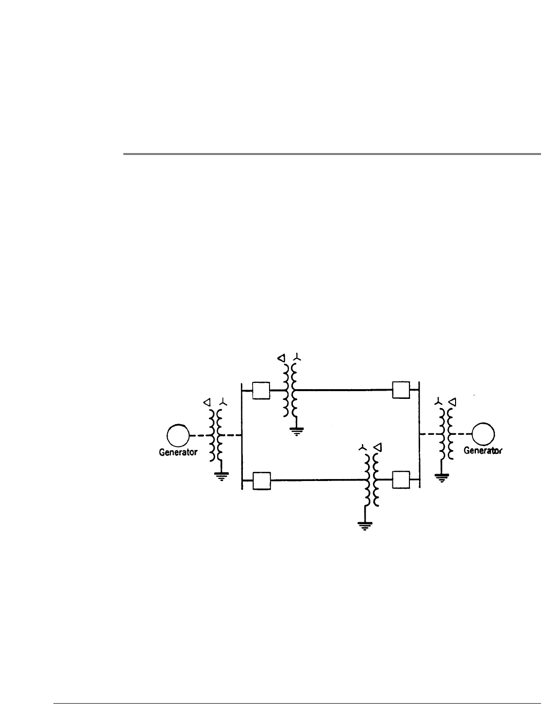
Fig. 16. Parallel circuits subject to mutual induction that are electrically independent so far as
zero~phase-sequence currents are concerned.

LINE PROTECTION WITH PILOT RELAYS 339
The conditions of Fig. 15 are extreme in view of the fact that the line section in which
induced current flows cannot directly contribute short-circuit current to the other circuit.
However, it is not an impossible situation. It can exist whenever electrically independent
circuits are closely paralleled, or in a case such as that illustrated in Fig. 16. Although these
two circuits are paralleled at their ends, they are independent so far as zero-phase-sequence
currents are concerned.
Situations that are more apt to be encountered are illustrated in Fig. 17. It is only necessary
in either case of Fig. 17 that the breaker of the faulty line be open at the end where the
lines are normally paralleled, in order to have the condition that can produce an
undesirable tripping tendency of the directional-ground relays of the sound line. This
breaker may be open either because it was tripped by its protective relays immediately when
the fault occurred and before the breaker at the other end could trip, or because the line
had been open at both ends and the breaker at the other end was reclosed first on a
persisting fault. Not only would the directional elements at both ends of the sound line
permit tripping, but the current magnitudes may be large enough so that selectivity would
not be obtained.
Sometimes it is even unnecessary that the breaker in the faulty line of Fig. 17 be open. If
the effect of mutual induction is great enough, it can overcome the tendency of the
unfaulted line to supply current to the fault, and actually reverse the direction of its
current.
Fig. 17. Situations in which lines are directly paralleled at one end only.
