Mason C. Russell. The art and science of protective relaying
Подождите немного. Документ загружается.

310 LINE PROTECTION WITH DISTANCE RELAYS
for such relays is usually given for the connections of A, the difference in ampere-turns can
be taken care of by assuming that the magnitude of the current supplied to C is 2/√
–
3 times
that supplied to A, or, in other words, that the CT ratio for Cis √
–
3/2–or 87%– of its actual
value. The actual CT ratio for any connection is the ratio of the high-voltage-circuit phase-
current magnitude to the relay phase-current magnitude under normal balanced
three-phase conditions.
Connection Ampere-Turns
A (I
a
- I
b
)N
B 3(I
a
- I
b
)N
C 2(I
a
- I
b
)N
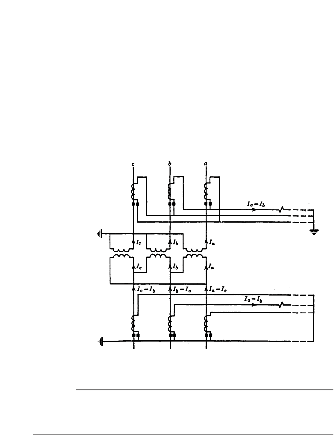
Figure 14 shows the high-tension and low-tension current connections for a single-coil type
of distance relay. The CT ratio is the same as that defined in the preceding paragraph.
EFFECT OF POWER-TRANSFORMER MAGNETIZING-CURRENT INRUSH
ON DISTANCE-RELAY OPERATION
The effect of power-transformer magnetizing-current inrush on distance-relay operation is
also discussed under the heading "Use of Low-Tension Current." It is the purpose here to
consider the case of inrush to the HV windings of the transformers at the far end or ends
of a line.
Fig. 14. Low-tension-current connections for a single-coil distance relay.

LINE PROTECTION WITH DISTANCE RELAYS 311
The writer does not know of any cases of tests, theoretical studies, or actual trouble in this
respect. Therefore, it is concluded that, if the possibility of distance-relay misoperation
exists, it must be extremely remote. The most severe inrush that can occur in existing
conventional power transformers would be less likely to operate a distance relay than
would a three-phase fault on the other side of the transformer bank. This is because the
rms magnitude of the initial inrush current is generally less than that of the fault current.
Furthermore, the inrush contains harmonic currents to which certain relays do not
respond as well as to the fundamental components. The high-speed zone of a distance
relay is not permitted to reach through transformers at the far ends of a line, and,
therefore, if any relay unit is to operate it would have to be either the second- or third-zone
unit. These units generally have enough time delay so that the inrush will have subsided
considerably before a unit could operate, which further lessens the likelihood of their
operation. And, finally, the distance relays in question will usually get only a part of the
inrush current in those cases in which misoperation would be most objectionable, such as
when energizing a transformer bank tapped to an important line. Therefore, there is little
wonder that this subject is not cause for concern.
THE CONNECTIONS OF GROUND DISTANCE RELAYS
Reference 11 shows that for accurate distance measurement, a ground relay may be
supplied with a phase-to-neutral voltage and the sum of the corresponding phase current
and an amount proportional to the zero-phase-sequence current. If there is another line
nearby that can induce voltage in the line under consideration when a ground fault occurs
anywhere, there must also be added to the phase current an amount proportional to the
zero-phase-sequence current of the other line. The addition of these zero-phase-sequence
quantities is called "current compensation." Reference 11 also describes an alternative to
current compensation called "voltage compensation," whereby the voltage is compensated
by zero-phase quantities. Compensation is necessary because variations in the distribution
of zero-phase-sequence current relative to the distribution of positive- and negative-phase-
sequence current would otherwise cause objectionable errors in distance measurement.
Ground distance relays can also be energized by zero-phase-sequence-voltage drop and
zero-phase-sequence current to measure distance by measuring the zero-phase-sequence
impedance.
l2
OPERATION WHEN PT FUSES BLOW
Distance relays that are capable of operating on less than normal load current may operate
to trip their breaker when a potential-transformer fuse blows. In one system, blown fuses
caused more undesired tripping than any other thing until suitable fusing was provided.
l3
Since potential-transformers are generally energized from a bus and supply voltage to the
relays of several lines, it is advisable to provide separate voltage circuits for the relays of
each line and to fuse them separately if fusing is to be used at all. With separate fusing,
trouble in the circuit of one set of relays will not blow the fuses of another circuit. The
principal objection to bus PT's is that "all the eggs are in one basket"; but, with separately
fused circuits, this objection is largely eliminated.
312 LINE PROTECTION WITH DISTANCE RELAYS
Neon lamps should be used for pilot indication of the voltage supply to each set of
distance relays.
When the relays do not have to operate on less than load current, instantaneous
overcurrent units can be used to prevent tripping for a blown fuse during normal load
conditions. The overcurrent-relay contacts are in series with the trip circuit. Undesired
tripping is still possible should a fault occur before the blown fuse has been replaced; it is
to minimize this possibility that the indicating lamps are recommended. If the ground-
fault current is high enough, a single set of three instantaneous overcurrent relays can be
used separately from the distance relays to prevent undesired tripping by either the phase
or ground relays; otherwise, a single ground overcurrent relay would be used for the
ground relays.
PURPOSEFUL TRIPPING ON LOSS OF SYNCHRONISM
When generators have gone out of synchronism, all ties between them should be opened
to maintain service and to permit the generators to be resynchronized. The separation
should be made only at such locations that the generating capacity and the loads on either
side of the point of separation will be evenly matched so that there will be no interruption
to the service.
14
Distance relays at those locations are sometimes suitable for tripping their
breakers on loss of synchronism, and in some aystems they are used for this purpose in
addition to their usual protective functions. However, as mentioned in Chapter 9,
additions or removals of generators or lines during normal operation will often change the
response of certain distance relays to loss of synchronism. Therefore, each application
should be examined to see if certain distance relays can always be relied on to trip.
A completely reliable method of tripping at preselected locations is available.
15
This
relaying equipment contains two angle-impedance units as described in Chapter 4, an
overcurrent unit, and several auxiliary relays. It is a single-phase equipment, which is all
that is necessary because loss of synchronism is a balanced three-phase phenomenon. The
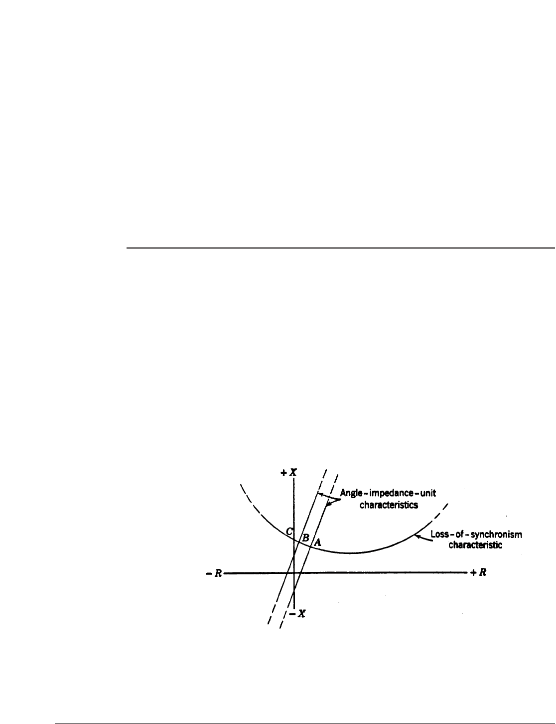
two angle-impedance units use the same one of the three combinations of current and
voltage used by phase distance relays for short-circuit protection. Figure 15 shows the
operating characteristics of the two angle-impedance units on an R-X diagram, together
with a loss-of-synchronism characteristic for the relay’s location on a tie line connecting the
Fig. 15. Relay for tripping on loss of synchronism.

LINE PROTECTION WITH DISTANCE RELAYS 313
generators that have lost synchronism. The significant feature of the equipment is that the
two angle-impedance units divide the diagram into the three regions A, B,and C. As the
impedance changes during loss of synchronism, the point representing this impedance
moves along the loss-of-synchronism characteristic from region AintoBand then into C,
or from Cinto Band then into A, depending on which generators are running the faster.
As the point crosses the operating characteristic of an angle-impendance unit, the unit
reverses its direction of torque and closes a contact to pick up an auxiliary relay. As the
impedance point moves into one region after another, a chain of auxiliary relays picks up,
one after the other. When the third region is entered, the last auxiliary relay of the chain
picks up and trips its breaker. There are two such chains–one for each direction of
movement–and the contacts of the two last auxiliary relays of the chains are connected in
parallel so that either one can trip the breaker.
The purpose of the overcurrent unit is to prevent tripping during hunting between the
generators at light load. This condition is represented by movement along a portion of the
loss-of-synchronism characteristic diametrically opposite to the portion shown in Fig. 15.
Such movement would also fulfill the requirements for tripping that have been described.
Relatively very little current flows during hunting at light load compared with the high
current flowing when generators pass through the 180° out-of-phase position which is in
the Bregion on the portion of the loss-of-synchronism characteristic shown in Fig. 15.
Therefore, the overcurrent unit's pickup can be adjusted so that the equipment will select
between hunting and loss of synchronism.
No other condition can cause the impedance point to move successively through the three
regions, and therefore the equipment is completely selective.
Changes in a system cannot cause the equipment to fail so long as there is enough current
to operate the overcurrent unit when synchronism is lost. The loss-of-synchronism
characteristic may shift up or down on the R-Xdiagram, or the characteristic may change
from one of overexcitation to one of underexcitation, without adversely affecting the
operation of the equipment.
When tripping is desired at a location where the current is too low to actuate a loss-of-
synchronism relay, remote tripping is necessary over a suitable pilot channel from a
location where a loss-of-synchronism relay can be actuated.
16
When two or more loss-of-synchronism relays are used at different locations, one or more
of these relays may need a supplementary single-step distance unit because the overcurrent
units may not provide the desired additional selectivity.
The locations where tripping is desired on loss of synchronism may change from time to
time as the relations between load and generation change. Under such circumstances, it is
desirable to have installations of loss-of-synchronism-relay equipments at several locations so
that the load dispatcher can select the equipments to be made operative during any period.
In lieu of complete freedom to choose the best locations to separate parts of a system
when synchronism is lost, it may be necessary to resort to some automatic "load shedding."
By such means, nonessential load can be dropped automatically either directly when the
tie breakers are tripped or indirectly through the operation of relays such as the
underfrequency type. This subject is treated in detail in Reference 24 of Chapter 13.
314 LINE PROTECTION WITH DISTANCE RELAYS
BLOCKING TRIPPING ON LOSS OF SYNCHRONISM
Tripping at certain locations is required when generators lose synchronism, but it should
be limited to those locations only. If distance relays at any other locations have a tendency
to trip, supplementary relaying equipment should be used to block tripping there. Also,
wherever tripping can occur during severe power swings when a system is recovering from
the effects of a shock, such as that caused by a short circuit, equipment to block tripping is
most desirable; tripping a sound line that is carrying synchronizing power would very likely
cause instability.
The method by which tripping on loss of synchronism can be blocked is very ingenious.
17
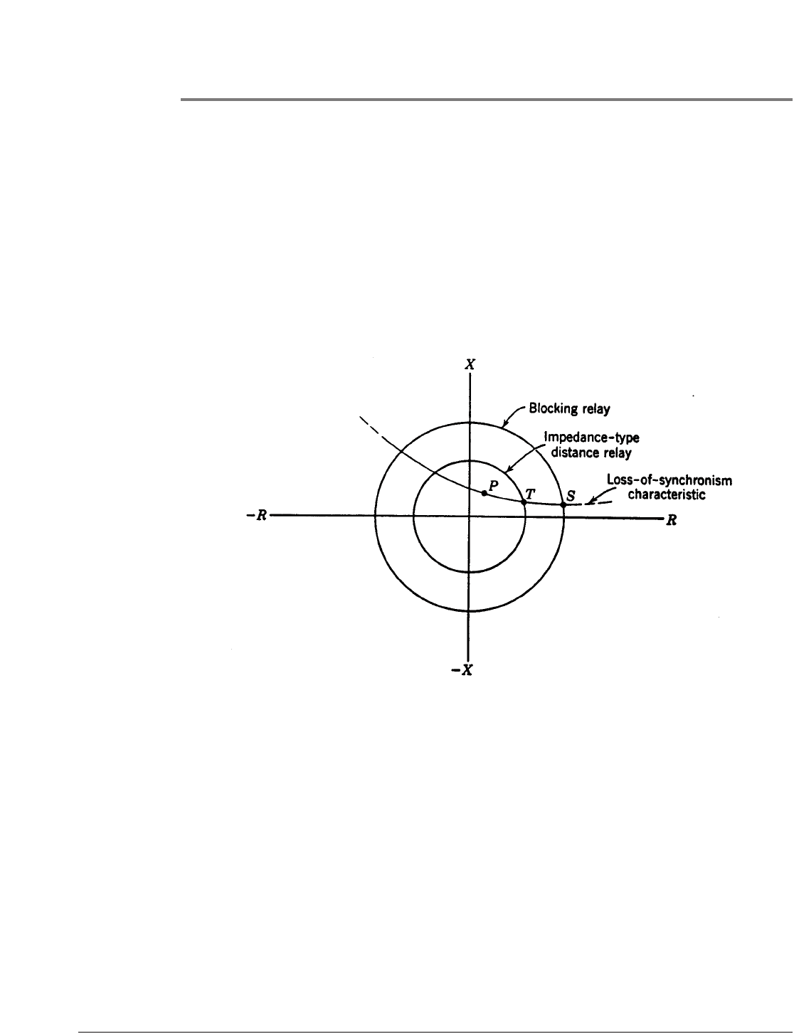
Consider the R-X diagram of Fig. 16. The point P represents the impedance for a three-
phase fault well within the operating characteristic of an impedance-type distance relay.
Assuming that the loss-of-synchronism characteristic passes through P, the problem, then,
is to devise a selective relaying equipment that will permit tripping when the fault
represented by P occurs, but not when loss of synchronism reaches a stage that is also
represented by P. The way in which this selection is made is based on the fact that the
change in impedance from the operating conditions just before the fault is instantaneous,
whereas the change in impedance during loss of synchronism is relatively slow. The
method used for recognizing this difference is to encircle the distance-relay characteristic
with a blocking-relay characteristic such as that shown on Fig. 16. (For balanced three-
phase conditions, such as those during loss of synchronism, all three phase distance relays
see the same impedance; therefore, the one characteristic represents all three relays.)
Then, a control circuit is provided so that, if the blocking relay operates sufficiently ahead
of a distance relay, as when the impedance is changing from S to T, the distance-relay trip
circuit will be opened. But, if the impedance changes instantly to any value such as P inside
the distance-relay characteristic, the trip circuit will not be opened.
Fig. 16. Relay characteristics of equipment of Fig. 17.
LINE PROTECTION WITH DISTANCE RELAYS 315
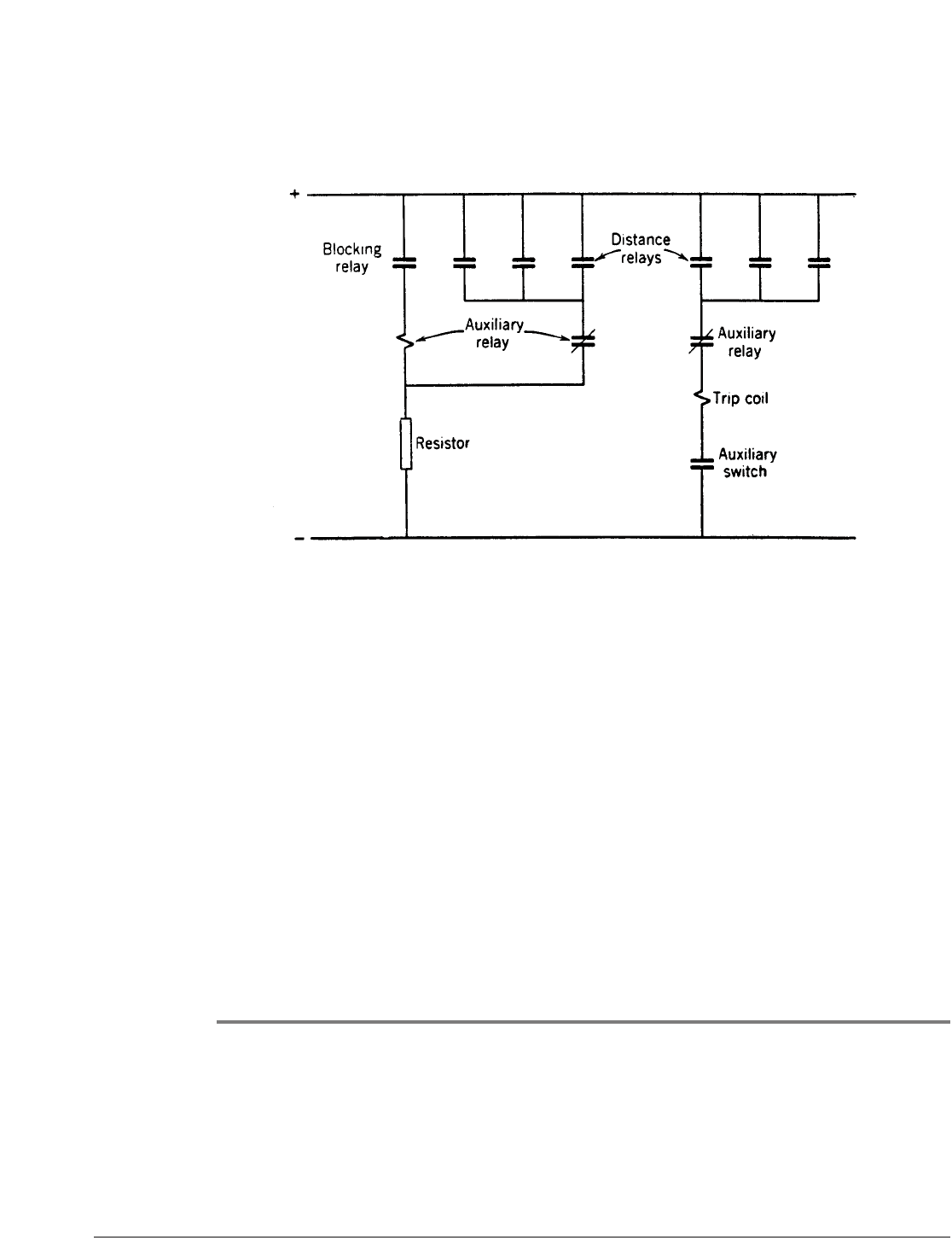
The circuit for blocking tripping is shown in Fig. 17. If the blocking relay closes its contact
to energize the coil of the auxiliary relay before any distance relay closes its contact to short
out the auxiliary-relay coil, the auxiliary relay will pick up and open its contact in the trip
circuit. The subsequent closing of a distance-relay contact in the circuit around the
auxiliary-relay coil will be ineffective because the auxiliary relay will have opened its
contact in this circuit. The auxiliary relay is given a little time delay to pick up so as to be
sure that it will not pick up when a fault occurs requiring tripping, and the distance and
blocking relays close contacts practically together.
The blocking relay may be an impedance type or a mho type so long as its characteristic
encircles the characteristic of the distance relays whose tripping is to be blocked. In
practice the blocking relay is single phase. At one time, some considered three blocking
relays necessary because a fault might still be on the system when blocking was required.
Today, this is thought to be an unnecessary complication because of the general use of
relatively high-speed relays. A single-phase blocking relay is permissible because loss of
synchronism is a balanced three-phase phenomenon. The blocking relay uses the same
voltage-and-current combination as one of the phase distance relays. Ground distance
relays using phase-to-neutral voltage and compensated phase current could also tend to
trip, and, therefore their tripping should also be blocked.
AUTOMATIC RECLOSING
Chapter 13 introduces the subject of automatic reclosing and describes the practices with
overcurrent relaying. Here, we are concerned with the practices with distance relaying.
Lines protected by distance relays usually interconnect generating sources. Consequently,
the problem arises of being sure that both ends are in synchronism before reclosing. "High-
speed reclosing," defined here as reclosing the breaker contacts in about 20 cycles after the
trip coil was energized to trip the breaker, cannot be used because of the inherent time
delay of distance relaying for faults near the ends of a line. In order to be sure that an arc
Fig. 17. Equipment for blocking tripping on loss of synchronism.

316 LINE PROTECTION WITH DISTANCE RELAYS
will not restrike when reclosing the line breakers, the line has to be disconnected at both
ends for a time long enough for the ionized gas in the arc path to be dispersed. This takes
from about 6 to 16 cycles, depending on the magnitude of the arc current and the system
voltage, the average being about 8 to 10 cycles.
18
To provide this time with high-speed
reclosing, both ends of a line must be tripped practically simultaneously. Since, with
distance relays, one end may trip 6 to 12 cycles or more ahead of the other, depending on
the intermediate-time adjustment, this additional time must be added to the reclosing
cycle. In other words, about the fastest permissible reclosing time with distance relays is 26
to 32 cycles or longer. The only exceptions are lines with wye-delta power transformers at
both ends; there simultaneous high-speed tripping is possible.
Because of the foregoing reclosing times and also the fact that inverse-time-overcurrent
relays are generally used for ground-fault protection, such lines require synchronism check,
as described in Chapter 13. Of course, one end of a line can be reclosed without
synchronism check. Synchronism check is unnecessary if there are enough other
interconnections between the generating sources that the line interconnects so that one
can be sure that both sides will always be in synchronism. Automatic reclosing can be very
harmful if it causes the connection of parts of a system that are out of synchronism; this is
known to have been the "last straw" that caused a major system shutdown.
It is usually the practice to provide one immediate (which is slower than high-speed)
reclosure followed by 2 or 3 time-delay reclosures and then lockout if the fault persists.
When a line ends in a power-transformer bank with no high-voltage breaker, but with a
grounding switch for remote tripping in the event of a transformer-bank fault, automatic
reclosing of the remote breaker is affected. Some users adjust ground-distance relays’
first-zone reach to 80% to 90% of the line (i.e., not to reach to the transformer) in order
that the first-zone unit will not operate when the grounding switch is closed. Then,
automatic reclosing is permitted only if a first-zone unit operates, thereby avoiding
reclosing on the grounding switch and a transformer fault. If a three-phase grounding
switch is used, the high-speed zone of the remote distance relays may be permitted to
reach into the transformer bank; this will permit automatic reclosure on the grounding
switch without harming the transformer, which may be permissible if the shock to the
system is not too great.
EFFECT OF PRESENCE OF EXPULSION PROTECTIVE GAPS
It is generally necessary to delay tripping by the high-speed zone of distance relaying if
a line is equipped with expulsion protective gaps. A minimum relay-operating time of 2
or 3 cycles is usually sufficient to prevent high-speed-relay tripping while an expulsion
protective gap is functioning. This additional delay in the tripping time is provided by
the addition of an auxiliary relay. The tripping circuit should be carried through the
protective-relay contacts to avoid undesired tripping because of overtravel of the
auxiliary relay.

LINE PROTECTION WITH DISTANCE RELAYS 317
EFFECT OF A SERIES CAPACITOR
A series capacitor can upset the basic premises on which the principles of distance and
directional relaying are founded. These premises are (1) that the ratio of voltage to current
at a relay location is a measure of the distance to a fault, and (2) that fault currents are
approximately reversed in phase only for faults on opposite sides of a relay location. A
series capacitor introduces a discontinuity in the ratio of voltage to current, and
particularly in the reactance component of that ratio, as a fault is moved from the relay
location toward and beyond a series capacitor. One can easily visualize the effect by
plotting the impedance points on an R-X diagram. As a fault is moved from the relay side
of the capacitor to the other side, the capacity reactance subtracts from the accumulated
line reactance between the relay and the fault. As a consequence, the fault may appear to
be much closer to the relay location or it may even have the appearance to some relays of
being back of the relay location.
One way that series capacitors are used
19
minimizes their adverse effect on distance relays.
A single capacitor bank is chosen to compensate no more than about half of the reactance
of a given line section; if a higher degree of compensation is used, the capacitors are
divided into two or more banks located at different places along a line. Also, a protective
gap is provided across each capacitor bank, and this gap flashes over immediately when a
fault occurs and effectively shorts out the capacitor bank while fault current flows. In other
words, the capacitor banks are in service normally, are shorted out while a fault exists, and
are returned to service immediately when the faulty line section is tripped.
Where capacitors are located otherwise, it will probably be necessary to add slight time
delay to the distance-relay trip circuit. For fault currents that are too low to dash over the
capacitor gap, it may be necessary to use phase-comparison relaying, probably with greater-
than-normal sensitivity.
COST-REDUCTION SCHEMES FOR DISTANCE RELAYING
Many ways have been suggested for reducing the cost of highspeed distance relaying so
that its use on lower-voltage circuits could be justified. What has been sought is a “class of
protection somewhere in the middle ground between the cost, performance, and
complexity of overcurrent and conventional 3-zone distance relays.”
20
These schemes may
be classified as follows:
(a) Abbreviated relays.
20
(b) Three conventional relays for phase faults and three conventional relays for ground
faults, except that certain units are used in common.
21
(c) Three conventional relays for both phase and ground faults by means of “current and
voltage switching.”
22
(d) One conventional relay for phase faults and/or one conventional relay for ground
faults by means of current and voltage switching.
l2,23
(e) One conventional relay for both phase and ground faults by means of current and
voltage switching.
22

318 LINE PROTECTION WITH DISTANCE RELAYS
Current and voltage switching is a means for automatically connecting the relay to the
proper current and voltage sources so that it will measure distance correctly for any fault
that occurs.
With the possible exception of (e), all these schemes are in use in this country, although
none of them very extensively. The greater the departure from the conventional
arrangement of three phase and three ground relays, the poorer is the quality of relaying.
They either have more time delay, are harder to apply, are less accurate, or require more
frequent maintenance. Voltage switching may not be permitted with capacitance potential
devices because of the errors that result from changing the burden. It is probably
economically feasible to standardize on one intermediate arrangement, but there is little
justification for much more.
To complete the list, other combinations of units should be included, most of which may
be classified as "abbreviated" relays. They consist of various combinations of units like
those used in conventional high relays.
7
Such relays supplement existing relays for
speeding up the protection. For example, three single-step directional-distance relays
might supplement directional-overcurrent inverse-time relays; this would provide high-
speed relaying for 80% to 90% of a line plus inverse-time-overcurrent relaying for the
remainder of the line and for back-up protection.
ELECTRONIC DISTANCE RELAYS
Electronic distance relays have been extensively tested
24
that are functionally equivalent to
conventional electromechanical distance relays, but that are faster and impose
considerably lower burden on a-c sources of current and voltage. At the same time, they are
more shock resistant. Their greater speed is most effective when they are used in
conjunction with a carrier-current or microwave pilot. When they are used alone, it is still
necessary to have some time delay for faults near the ends of a line, which tends to reduce
the advantage of a higher-speed first-zone unit.
The lower-burden characteristic of electronic relays may contribute to less expensive
current and voltage transformers, and therefore may increase the use of such relays even
though the greater speed may not be required.
Apart from differences in physical characteristics, the basic principles of electromechanical
distance relays and their application apply equally well to electronic distance relays.
PROBLEMS
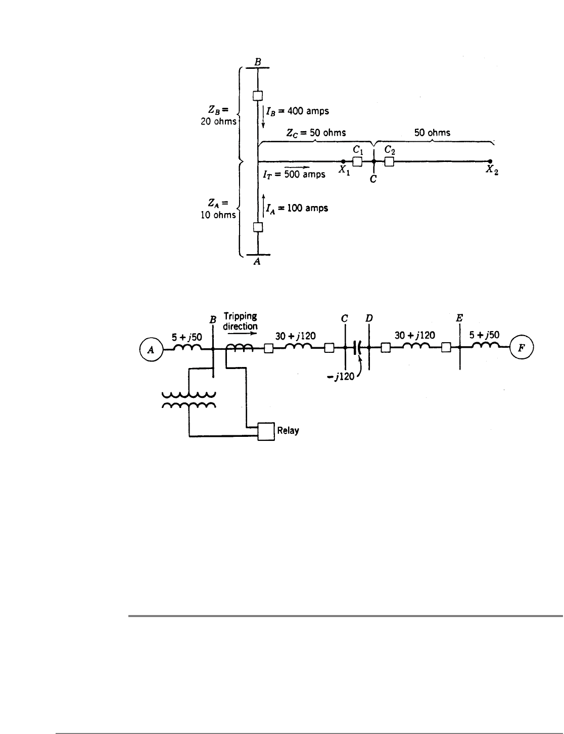
1. Referring to Fig. 18, it has been determined that load transfer from Ato Bor from Bto
Aprevents setting a distance relay at either Aor Bwith a greater ohmic reach than just
sufficient to protect a l00-ohm, 2-terminal line with a 25% margin (i.e., third-zone reach =
125 ohms).
a.What is the apparent impedance of the fault at X
1
to the relay at A? Can the relay at A
see the fault before the breaker at Bhas tripped?
b.Can the relay at B see the fault at X
1
before the breaker at Ahas tripped? Why?
LINE PROTECTION WITH DISTANCE RELAYS 319
c.If, for a fault at X
2
, breaker C
2
fails to open, will the fault be cleared by relays at Aand
B? Assume the same relative fault-current magnitudes as for aand b.
d.By what means can the fault at X
2
be cleared?
2. Show the positive-phase-sequence impedances of the line sections and series capacitor
of Fig. 19 on an R-Xdiagram as seen by phase distance relays at B, neglecting the effect of
a protective gap across the capacitor. Comment on the use of distance and directional
relays at B.
BIBLIOGRAPHY
1. "New Distance Relays Know Faults from Swings," by W. A. Morgan, Elec.World, 124(Oct.
27, 1945), pp. 85-87.
2. Circuit Analysis of A-C Power Systems,Vols. I and II, by Edith Clarke, John Wiley & Sons,
New York, 1943, 1950.
3. "Reactance Relays Negligibly Affected by Arc Impedance," by A. R. van C. Warrington,
Elec. World, 98,No. 12 (Sept. 19, 1931), pp. 502-505.
Fig. 19. Illustration for Problem 2.
Fig. 18. Illustration for Problem 1.
