Mason C. Russell. The art and science of protective relaying
Подождите немного. Документ загружается.

BUS PROTECTION 241
THE FAULT BUS
1
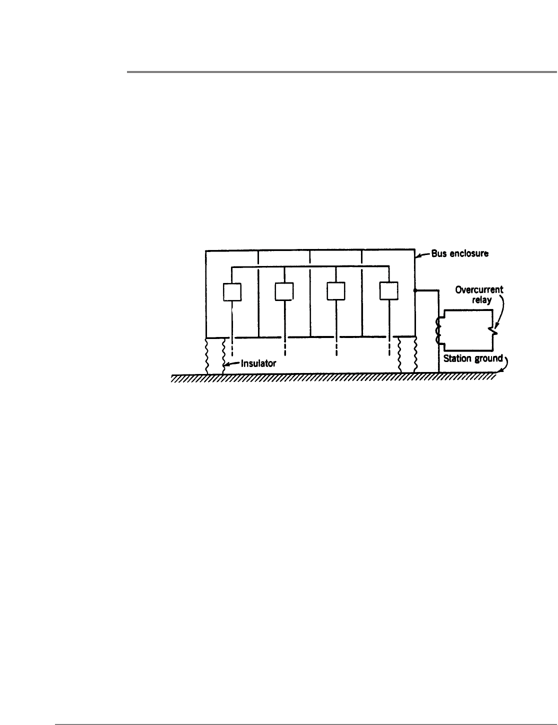
The fault-bus method consists of insulating the bus-supporting structure and its switch
gear from ground; interconnecting all the framework, circuit-breaker tanks, etc.; and
providing a single ground connection through a CT that energizes an overcurrent relay, as
illustrated schematically in Fig. 2. The overcurrent relay controls a multicontact auxiliary
relay that trips the breakers of all circuits connected to the bus. The maximum
effectiveness in obtained by this method when the switchgear is of the isolated-phase
construction, in which event all faults will involve ground. However, it is possible to design
other types of switchgear with special provisions for making ground faults the most
probable. Of course, if interphase faults not involving ground can occur, and if CT’s and
conventional differential relaying have to be used for protection against such faults, the
fault-bus method would probably not be justified.
This method is most applicable to new installations, particularly of the metal-clad type,
where provision can be made for effective insulation from ground. It has been more
favored for indoor than for outdoor installations. Certain existing installation may not be
adaptable to fault-bus protection, owing to the possibility of other paths for short-circuit
current to flow to ground through concrete-reinforcing rods or structural steel. It is
necessary to insulate cable sheaths from the switchgear enclosure or else cable ground-fault
currents may find their way to ground through the fault-bus CT and improperly trip all the
switchgear breakers. An external flashover of an entrance bushing will also improperly trip
all breakers, unless the bushing support is insulated from the rest of the structure and
independently grounded.
If a sectionalized bus structure is involved, the housing of each section must be insulated
from adjoining sections, and separate fault-bus relaying must be employed for each
section. The fault-bus method does not provide overlapping of protective zones around
circuit breakers; and, consequently, supplementary relaying is required to protect the
regions between bus sections.
Some applications have used a fault-detecting overcurrent relay, energized from a CT in
the neutral of the station-grounding transformer or generator, with its contact in series
with that of the fault-bus relay, to guard against improper tripping in the event that the
fault-bus relay should be operated accidentally; without some such provision, the
accidental grounding of a portable electric tool against the switchgear housing might pass
enough current through the fault-bus ground to operate the relay and trip all the breakers,
Fig. 2. Schematic diagram of the fault-bus method of protection.

242 BUS PROTECTION
unless the pickup of the relay was higher than the current that it could receive under such
a circumstance.
Consideration should be given to the possibility of people being able to make contact
between the switchgear housing and ground, to avoid the possibility of contact with high
voltage should a ground fault occur; although the ground connection would have very low
impedance, high current flowing through it could produce dangerously high voltage. This
requirement also makes it desirable to ground all relay, meter, and control circuits to the
switchgear housing rather than by means of a separate connection to the station ground.
DIRECTIONAL-COMPARISON RELAYING
The principle of “directional comparison” used for transmission-line relaying has been
adapted to bus protection in order to avoid the problem of matching current-transformer
ratings and characteristics.
2
Basically, the contacts of directional relays in all source circuits
and the contacts of overcurrent relays in purely load circuits are interconnected in such a
way that, if fault current flows toward the bus, the equipment will operate to trip all bus
breakers unless sufficient current is flowing away from the bus in any circuit.
This principle has been used only with ground relays, on the basis that most bus faults start
as ground faults, or at least that they very quickly involve ground. This greatly reduces the
cost of the equipment over that if phase relays were also used; even so, it is still more costly
than most relaying equipments for bus protection. Of course, if it saves investment in new
current transformers and their installation cost, it would be economically attractive.
The principal disadvantage of this type of equipment is the greater maintenance required
and the greater probability of failure to operate because of the large number of contacts in
series in the trip circuit. Another disadvantage is that connections from the current
transformers in all the circuits must be run all the way to the relay panel. Of course, if only
ground relays were used, only two connections to the CT’s of each circuit would be
required. If phase relays were used, they would depend on bus voltage for polarization,
and, therefore, they might not operate for a metallic short circuit that reduced the voltage
practically to zero.
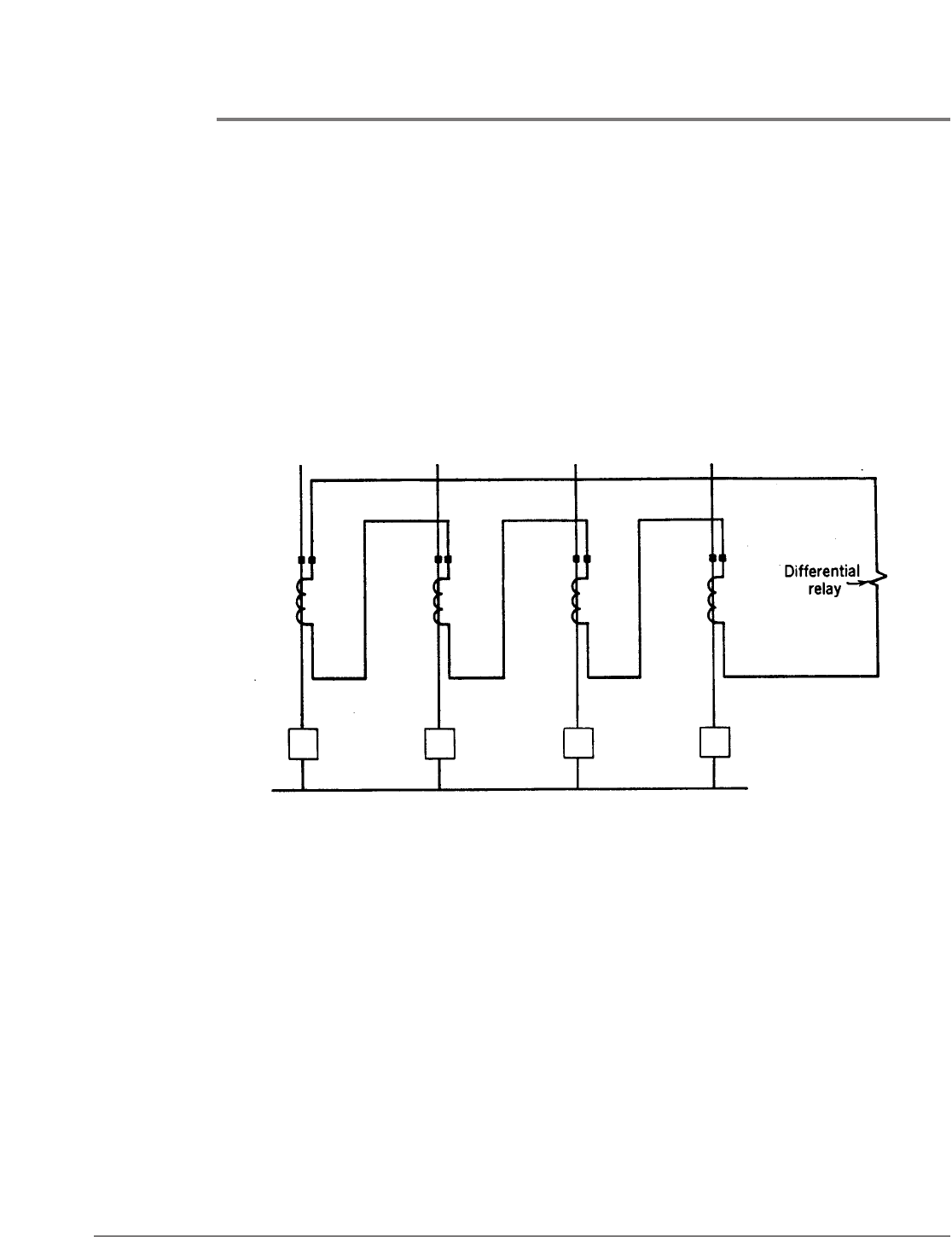
Fig. 3. Bus protection by current-differential relaying.

BUS PROTECTION 243
CURRENT-DIFFERENTIAL RELAYING WITH OVERCURRENT RELAYS
The principle of current-differential relaying has been described. Figure 3 shows its
application to a bus with four circuits. All the CT’s have the same nominal ratio and are
interconnected in such a way that, for load current or for current flowing to an external
fault beyond the CT’s of any circuits, no current should flow through the relay coil,
assuming that the CT’s have no ratio or phase-angle errors. However, the CT’s in the faulty
circuit may be so badly saturated by the total fault current that they will have very large
errors; the other CT’s in circuits carrying only a part of the total current may not saturate
so much and, hence, may be quite accurate. As a consequence, the differential relay may
get a very large current, and, unless the relay has a high enough pickup or a long enough
time delay or both, it will operate undesirably and cause all bus breakers to be tripped.
The greatest and most troublesome cause of current-transformer saturation is the transient
d-c component of the short-circuit current. It is easy to determine if the CT’s in the faulty
circuit will be badly saturated by a fault-current wave having a d-c component, by using the
following approximate formula:
(√
–
2)(10
8
) R
2
I
1
TN
1
B
max
= ————————
AN
2
2
where B
max
= maximum flux density in CT core in lines per square inch.
R
2
= resistance of CT-secondary winding and leads up to, but not including, the
relay circuit, in ohms.
I
1
= rms magnitude of symmetrical component of primary fault current in
amperes.
T = time constant of primary d-c component in seconds.
A = cross-sectional area of CT core in square inches.
N
1
= number of primary turns (= 1 for bushing CT’s).
N
2
= number of secondary turns.
For values of B
max
greater than about 100,000 lines per square inch, there will be saturation
in modern CT’s, and for values greater than about 125,000 lines there will be appreciable
saturation, the degree being worse the higher the value of B
max
. For instantaneous relays,
B
max
should be no more than about 40,000 lines because the residual flux can be as high
as about 60,000 lines. For CT’s that are 10 or 15 years old, about 77,500 lines represents
saturation flux density.
Considering the effect of the d-c time constant, it will become evident that the nearer a bus
is to the terminals of a generator, the greater will be the CT saturation. Typical d-c time
constants for different circuit elements are:
Generators 0.3 second
Transformers 0.04 second
Lines 0.01 second
It makes a tremendous difference, therefore, whether the fault-current magnitude is
limited mostly by line impedance or by generator impedance.
244 BUS PROTECTION
If the d-c component will not badly saturate the CT’s, it is a relatively simple matter to
calculate the error characteristics of the CT’s by the methods already described, and to
find out how much current will flow in the differential relay. Knowing this magnitude of
current and the magnitude for which the differential relay must operate for bus faults, one
can choose the pickup and time settings that will give the best protection to the bus and
still provide selectivity for external faults.
But, if the d-c saturation is severe, and it usually is, the problem is much more difficult,
particularly if instantaneous relaying is desired. Two methods of analysis have been
presented. One is a method for first calculating the differential current and then
determining the response of an overcurrent relay to this current.
3
The other is a method
whereby the results of a comprehensive study can be applied directly to a given installation
for the purpose of estimating the response of an overcurrent relay.
4
Because of the
approximations and the uncertainties involved (and probably also because of the labor
involved), neither of these two methods is used very extensively, but, together with other
investigations, they provide certain very useful guiding principles.
Perhaps the most useful information revealed by these and other
5,6
studies is the effect of
resistance in the differential branch on the magnitude of current that can flow in that
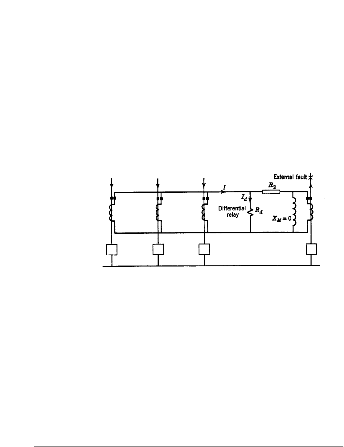
branch. Figure 4 is a one-line diagram of the CT’s and differential relay for a bus with four
feeders, showing an external short circuit on one of the feeders. Figure 4 shows the
equivalent circuit of the CT in the feeder having the short circuit. If that CT is assumed to
be so completely saturated that its magnetizing reactance is zero, neglecting the air-core
mutual reactance, the secondary current (I) from all the other CT’s will divide between the
differential branch and the saturated CT secondary, and the rms value of the differential
current (I
d
) will be no higher than:
R
2
I
d
= I ———--
( )
R
d
+ R
2
where R
2
includes the aecondary-winding resistance of the CT in the faulty circuit. The
effect of relay-coil saturation must be taken into account in using this relation. Of course,
the differential current will quickly decrease as the fault-current wave becomes
symmetrical. However, studies have shown that, depending on the circuit resistances, the
rms value of the differential current (I
d
) can momentarily approach the fault-current
magnitude (I) expressed in secondary terms. Where this is possible, instantaneous
Fig. 4. Distribution of current for an external fault.

BUS PROTECTION 245
overcurrent relays are not applicable unless sufficient resistance can be added to the
differential branch. The amount of such additional resistance should not be enough to
cause too high voltages when very high currents flow to a bus fault. Nor should the
resistance be so high that the CT’s could not supply at least about 1.5 times pickup current
under minimum bus-fault-current conditions. If we assume the CT’s in the faulty circuit to
be so badly saturated that their magnetizing reactance is zero, and that all the other CT’s
maintain their nominal ratio, the division of current between the differential relays and
the secondaries of the saturated CT’s, and the effects of adding resistance to the
differential branch, may be calculated assuming symmetrical sinusoidal currents; the
results will be conservative in that the differential relays will not have as great an operating
tendency as the calculations would indicate.
The foregoing furnishes a practical rule for obtaining the best possible results with any
current-differential-relaying application. This rule is to make the junction point of the CT’s
at a central location with respect to the CT’s and to use as large-diameter wire as practical
for the interconnections. The fact that the CT secondary windings have appreciable
resistance makes it impractical to try to go too far toward reducing the lead resistance.
Resistance in the leads from the junction point to the differential relays is beneficial to a
certain extent, as already mentioned.
Another rule that is generally followed is to choose CT ratings so that the maximum
magnitude of external-fault current is less than about 20 times the CT rating.
7
Some allow
this multiple to go to 30 or more, and others
8
try to keep it below 10. In an existing
installation with multiratio bushing CT’s, use the highest turns ratio.
To prevent differential-relay operation should a CT open-circuit, the relay pickup is often
made no less than about twice the load current of the most heavily loaded circuit;
8
if the
magnitude of groundfault current is sufficiently limited by neutral-grounding impedance,
lower pickup may be required and additional fault-detecting means may be required to
prevent operation should a CT open-circuit, such as by the use of an overcurrent relay
energized from a CT in the grounded-neutral source, and with its “a” contacts in series
with the trip circuit.
Some instantaneous overcurrent relays are used for current-differential relaying, but
inverse-time induction-type overcurrent relays are the most common; the induction
principle makes these relays less responsive to the d-c and harmonic components of the
differential current resulting from CT errors because of saturation. Time delay is most
helpful to delay differential-relay operation long enough for the transient differential
current due to CT errors to subside below the relay’s pickup; from 0.2 second to 0.5 second
is sufficient for most applications. The fact that a relay will overtravel after the current has
dropped below the pickup value should be taken into account.
Where not all the CT’s are of the same ratio, sometimes the practice is to provide current-
differential relaying only for ground faults. To accomplish this, auxiliary CT’s are
connected in the neutral of the CT’s of each circuit, and the ratios of these auxiliary CT’s
are chosen to compensate for the differences in ratio of the main CT’s. The ratio accuracy
of such auxiliary CT’s should be investigated to determine their suitability. Of course,
auxiliary CT’s might be used to permit phase-fault relaying, but it would be much more
expensive. In general, auxiliary CT’s should be avoided whenever possible.
246 BUS PROTECTION
PARTIAL-DIFFERENTIAL RELAYING
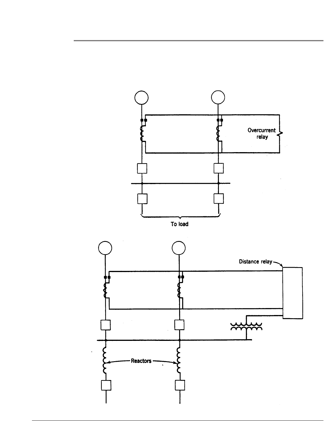
Partial-differential relaying is a modification of current-differential relaying whereby only
the CT’s in generating-source (either local or distant) circuits are paralleled, as illustrated
in Fig. 5. This is not done because of any advantage to be gained by omitting the other
CT’s in the purely load circuits, but either because there are no CT’s to be used or because
those that are available are not suitable for complete current-differential relaying.
Fig. 5. Partial differential relaying with overcurrent relays.
Fig. 6. Partial differential relaying with distance relays.

BUS PROTECTION 247
Two types of partial-differential relaying have been used, one type employing overcurrent
relays and the other employing distance relays. The protection provided by the overcurrent
type is much like that provided by back-up relays in the individual source circuits. The
overcurrent type must have enough time delay to be selective with the relays of the load
circuits for external faults in these circuits. Also, it must have a pickup higher than the
total maximum-load current of all source circuits. The only advantages of partial-
differential relaying with overcurrent relays are (1) that local protective equipment is
provided for bus protection, and (2) that back-up protection is provided for the load
circuits.
A second type of partial-differential-relaying equipment uses distance relays.
9,10
This type is
applicable where all the load circuits have current-limiting reactors, as illustrated in Fig. 6.
So long as two or more of the load circuits are not paralleled a short distance from the bus,
the reactors introduce enough reactance into the circuits so that the distance relays can
select between faults on the bus side and faults on the load side of the reactors. In some
actual applications, only ground distance relays have been used on the basis that all bus
faults will involve ground sooner or later. Because a fault in one of the source circuits that
badly saturates its CT’s will tend to cause the distance relays to operate undesirably, such a
possibility must be carefully investigated. Otherwise, this type of relaying can be both fast
and sensitive.
One application has been described in which distance relays were used for station-service
bus protection and there were no reactors in the load circuits.
10
Instead, selectivity with the
load-circuit relays was obtained by adding a short time delay to the operating time of the
distance relays.
CURRENT-DIFFERENTIAL RELAYING WITH
PERCENTAGE-DIFFERENTIAL RELAYS
As in differential relaying for generators and transformers, the principle of percentage-
differential relaying is a great improvement over overcurrent relays in a differential CT
circuit. The problem of providing enough restraining circuits has been largely solved by
socalled “multi restraint” relays.
5
By judicious grouping of circuits and by the use of two
relays per phase where necessary, sufficient restraining circuits can generally be provided.
Further improvement in selectivity is provided by the “variable-percentage” characteristic,
5
like that described in connection with generator protection; with this characteristic, one
should make sure that very high internal-fault currents will not cause sufficient restraint to
prevent tripping.
This type of relaying equipment is available with operating times of the order of 3 to 6
cycles (60-cycle basis). It is not suitable where high-speed operation is required.
As in current-differential relaying with overcurrent relays, the problem of calculating the
CT errors is very difficult. The use of percentage restraint and the variable-percentage
characteristic make the relay quite insensitive to the effects of CT error. Nevertheless, it is
recommended that each application be referred to the manufacturer together with all the
necessary data.
A disadvantage of this type of equipment is that all CT secondary leads must be run to the
relay panel.
248 BUS PROTECTION
VOLTAGE-DIFFERENTIAL RELAYING WITH “LINEAR COUPLERS”
The problem of CT saturation is eliminated at its source by air-core CT’s called “linear
couplers.’’
11
These CT’s are like bushing CT’s but they have no iron in their core, and the
number of secondary turns is much greater. The secondary-excitation characteristic of
these CT’s is a straight line having a slope of about 5 volts per 1000 ampere-turns.
Contrasted with conventional CT’s, linear couplers may be operated without damage with
their secondaries open-circuited. In fact, very little current can be drawn from the
secondary, because so much of the primary magnetomotive force is consumed in
magnetizing the core.
The foregoing explains why the linear couplers are connected in a voltage-differential
circuit, as shown schematically in Fig. 7. For normal load or external-fault conditions, the
sum of the voltages induced in the secondaries is zero, except for the very small effects of
manufacturing tolerances, and there is practically no tendency for current to flow in the
differential relay.
When a bus fault occurs, the voltages of the CT’s in all the source circuits add to cause
current to flow through all the secondaries and the coil of the differential relay. The
differential relay, necessarily requiring very little energy to operate, will provide high-speed
protection for a relatively small net voltage in the differential circuit.
The application of the linear-coupler equipment is most simple, requiring only a
comparison of the possible magnitude of the differential voltage during external faults,
because of differences in the characteristics of individual linear couplers, with the
magnitude of the voltage when bus faults occur under conditions for which the fault-
current magnitude is the lowest. Except when ground-fault current is severely limited by
neutral impedance, there is usually no selectivity problem. When such a problem exists, it
is solved by the use of additional more-sensitive relaying equipment, including a
supervising relay that permits the more-sensitive equipment to operate only for a single-
phase-to-ground fault.
12
Fig. 7. Bus protection with voltage-differential relaying.
BUS PROTECTION 249
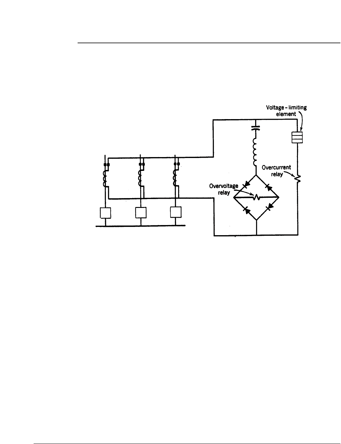
CURRENT-DIFFERENTIAL RELAYING WITH OVERVOLTAGE RELAYS
A type of high-speed relaying equipment employing current-differential relaying with
overvoltage relays also eliminates the problem of current-transformer saturation, but in a
different manner from that described using linear couplers. With this equipment,
conventional bushing CT’s (or other CT’s with low-impedance secondaries) are used, and
they are differentially connected exactly as for current relaying already described; the only
difference is that overvoltage rather than overcurrent relays are used.
13
In effect, this equipment carries to the limit the beneficial principle already described of
adding resistance to the differential branch of the circuit. However, in this equipment, the
impedance of the over-voltage-relay’s coil is made to appear to the circuit as resistance by
virtue of a full-wave rectifier, as illustrated in Fig. 8. Hence, the efficiency of the equipment
is not lowered as it would be if a series resistor were used.
The capacitance and inductance, shown in series with the rectifier circuit, are in series
resonance at fundamental system frequency; the purpose of this is to make the relay
responsive to only the fundamental component of the CT secondary current so as to
improve the relay’s selectivity. It has the disadvantage, however, of slowing the voltage
response slightly, but this is not serious in view of the high-speed operation of an
overcurrent-relay element now to be described.
Because the effective resistance of the voltage-relay’s coil circuit is so high, being
approximately 3000 ohms, a voltage-limiting element must be connected in parallel with
the rectifier branch, or else excessively high CT secondary voltages would be produced
when bus faults occurred. As shown in Fig. 8, an overcurrent-relay unit in series with the
voltage limiter provides high-speed operation for bus faults involving high-magnitude
currents. Since the overcurrent unit is relied on only for high-magnitude currents, its
pickup can easily be made high enough to avoid operation for external faults.
The procedure for determining the necessary adjustments and the resulting sensitivity to
low-current bus faults is very simple and straightforward, requiring only a knowledge of the
CT secondary excitation characteristics and their secondary impedance.
Fig. 8. Bus protection using current-differential relaying with overvoltage relays.

250 BUS PROTECTION
For the best possible results, all CT’s should have the same rating, and should be a type,
like a bushing CT with a distributed secondary winding, that has little or no secondary
leakage reactance.
COMBINED POWER-TRANSFORMER AND BUS PROTECTION
Figure 9 shows a frequently encountered situation in which a circuit breaker is omitted
between a transformer bank and a low-voltage bus. If the low-voltage bus supplies purely
load circuits without any back-feed possible from generating sources, the CT’s in all the
load circuits may be paralleled and the transformer-differential relay’s zone of protection
may be extended to include the bus.
Figure 10 shows two parallel high-voltage lines feeding a power-transformer bus with no
circuit breaker between the transformer and the bus. As shown in the figure, a three-
winding type of percentage-differential relay will provide good protection for the bus and
the transformer.
In Fig. 11, the two high-voltage lines are from different stations and may constitute an
interconnection between parts of a system. Consequently, much higher load currents may
flow through these circuits than the rated load current of the power transformer.
Therefore, the CT ratios in the high-voltage circuits may have to be much higher than one
would desire for the most sensitive protection of the power transformer. And therefore, the
protective scheme of Fig. 10, though generally applicable, is not as sensitive to transformer
faults as the arrangement of Fig. 11. Bushing CT’s can generally be added to most power
transformers, but it is considerably less expensive and less troublesome if the power
transformers are purchased with the two sets of CT’s already installed. It is almost
axiomatic that, whenever circuit breakers are to be omitted on the high-voltage side of
power transformers, two sets of bushing CT’s should be provided on the transformer high-
voltage bushings. The arrangement of Fig. 11 can be extended to accommodate more
high-voltage lines or more power transformers, although, as stated in Chapter 11, it is not
considered good practice to omit high-voltage breakers when two or more power-
transformer banks rated 5000 kva or higher are paralleled.
