Lyons W.C. (ed.). Standard handbook of petroleum and natural gas engineering.2001- Volume 1
Подождите немного. Документ загружается.

Air and Gas Drilling
855
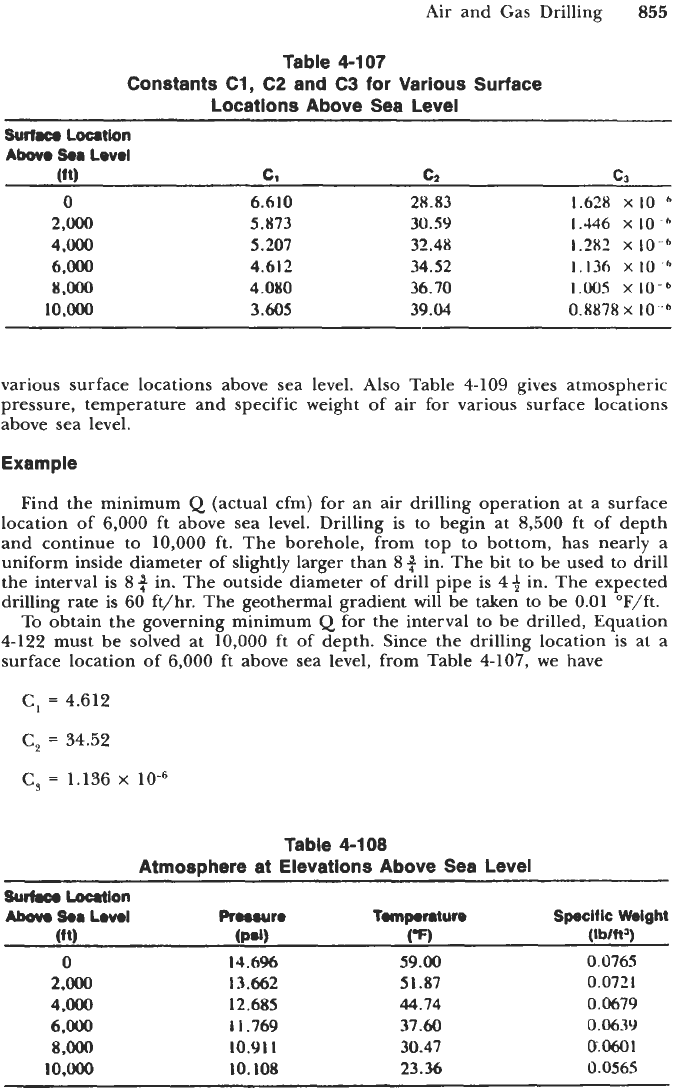
Table 4-107
Constants C1, C2 and C3 for Various Surface
Locations Above Sea Level
Surface
Loution
Abo
5.6
Level
(ft)
c1
C2
c3
0
6.610 28.83 1.628
XIO
6
2,Ooo
5.873
30.59
1.446
x
IO
4.000 5.207 32.48
1.28'
x
IO
6,000
4.612 34.52
1,136
x
IO
8.m
4.080 36.70
1.00.5
x
10-b
10.000
3.605
39.04 0.8878~
IO
various surface locations above sea level. Also Table
4-109
gives atmospheric
pressure, temperature and specific weight of air for various surface locations
above sea level.
Example
Find the minimum
Q
(actual cfm) for an air drilling operation at a surface
location of
6,000
ft above sea level. Drilling is to begin at
8,500
ft of depth
and continue to
10,000
ft. The borehole, from top to bottom, has nearly a
uniform inside diameter of slightly larger than
8+
in. The bit to be used to drill
the interval is
Sq
in. The outside diameter of drill pipe is
49
in. The expected
drilling rate is
60
ft/hr. The geothermal gradient will be taken to be
0.01
OF/ft.
To obtain the governing minimum
Q
for the interval to be drilled, Equation
4-122
must be solved at
10,000
ft of depth. Since the drilling location is at a
surface location of
6,000
ft above sea level, from Table
4-107,
we have
C,
=
4.612
C,
=
34.52
C,
=
1.136
x
Table 4-108
Atmosphere at Elevations Above
Sea
Level
SUM
Loatlon
Aborn
5..
Lwol
Proowro
Tomporntun
Specltlc
Weight
(11)
(P.1)
(-7
(wnq
0
14.6%
59.00
0,0765
2.000
13.662
51.87
0.0721
4
.OOo
12.685
44.74
0.0679
6.000
1
I
.769 37.60
0.0639
8
.oOO
10.9
I
I
30.47
CY.0601
1o.OOo
IO.
108
23.36 0.0565
856
Drilling and Well Completions
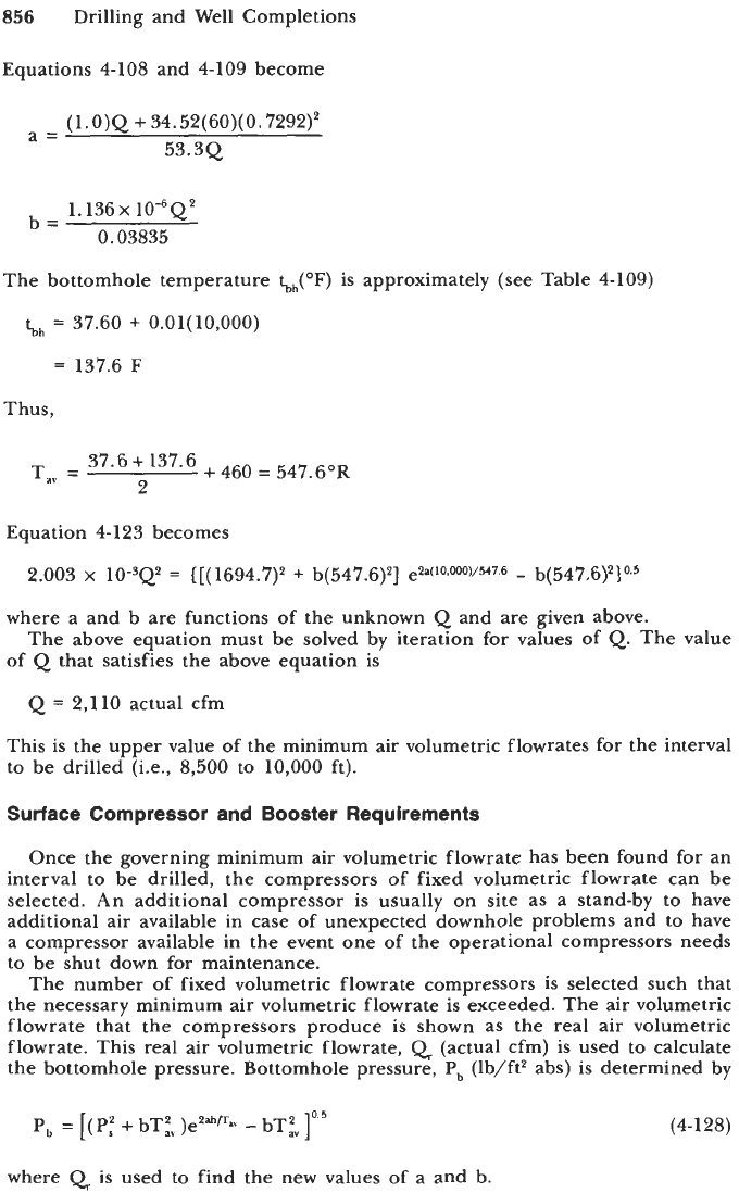
Equations
4-108
and
4-109
become
(l.0)Q
+
34.52(60)(0.7292)'
53.3Q
a=
1.136
x
lo-"'
0.03835
b=
The bottomhole temperature
tbh(OF)
is approximately
kh
=
37.60
+
O.Ol(l0,OOO)
=
137.6
F
Thus,
(see Table
4-109)
Equation
4-123
becomes
2.003
x
10-3Q2
=
{[(1694.7)'
+
b(547.6)2]
e2a(10.000)/547.6
-
b(547.6)2}0.5
where a and b are functions of the unknown
Q
and are given above.
of
Q
that satisfies the above equation is
The above equation must be solved by iteration for values of
Q.
The value
Q
=
2,110
actual cfm
This is the upper value
of
the minimum air volumetric flowrates for the interval
to be drilled (i.e.,
8,500
to
10,000
ft).
Surface Compressor and Booster Requirements
Once the governing minimum air volumetric flowrate has been found for an
interval to be drilled, the compressors of fixed volumetric flowrate can be
selected. An additional compressor is usually on site as a stand-by to have
additional air available in case of unexpected downhole problems and to have
a compressor available in the event one
of
the operational compressors needs
to be shut down for maintenance.
The number
of
fixed volumetric flowrate compressors is selected such that
the necessary minimum air volumetric flowrate is exceeded. The air volumetric
flowrate that the compressors produce is shown as the real air volumetric
flowrate. This real air volumetric flowrate,
Q
(actual cfm) is used to calculate
the bottomhole pressure. Bottomhole pressure,
P,
(lb/ft2 abs) is determined by
P,
=
[(P:
+
bT;" )ezahnav
-
bTf]0'5
(4-1 28)
where
Q
is used to find the new values of a and b.
Air and Gas Drilling
857
Knowing the bottomhole pressure, the number of bit orifice openings and
the inside diameter of these openings, the pressure inside the drill pipe just
above the bit and the surface injection pressure can be found.
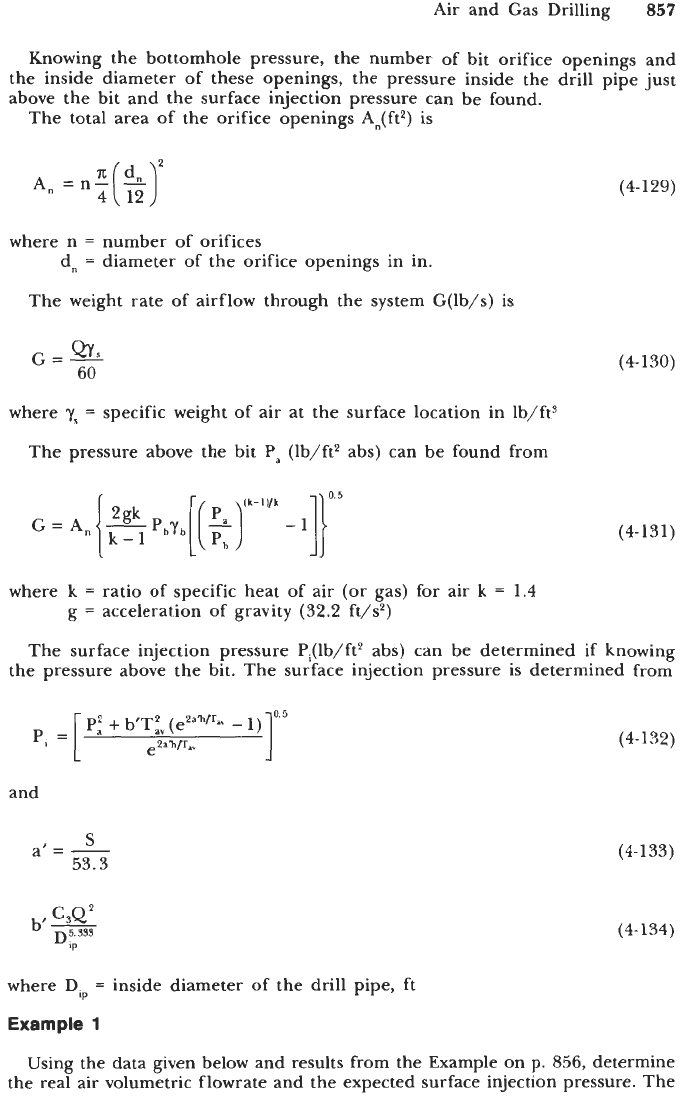
The total area of the orifice openings A,(ft2) is
where n
=
number of orifices
dn
=
diameter of the orifice openings in in.
The weight rate of airflow through the system G(lb/s) is
G=-
Qr
s
60
where
y,
=
specific weight of air at the surface location in lb/ft3
The pressure above the bit
Pa
(lb/ft2 abs) can be found from
(4-1 29)
(4-130)
(4-131)
where
k
=
ratio
of
specific heat of air (or gas) for air
k
=
1.4
g
=
acceleration of gravity
(32.2
ft/s2)
The surface injection pressure Pi(lb/ft2 abs) can be determined if knowing
the pressure above the bit. The surface injection pressure is determined from
P:
+
b'Tiv (ezanpav
-
and
S
a'
=
-
53.3
C,Q2
b'pF
P
(4-132)
(4-1
33)
(4-1
34)
where
Dip
=
inside diameter of the drill pipe,
ft
Example
1
Using the data given below and results from the Example on p.
856,
determine
the real air volumetric flowrate and the expected surface injection pressure. The
858
Drilling and Well Completions
8$
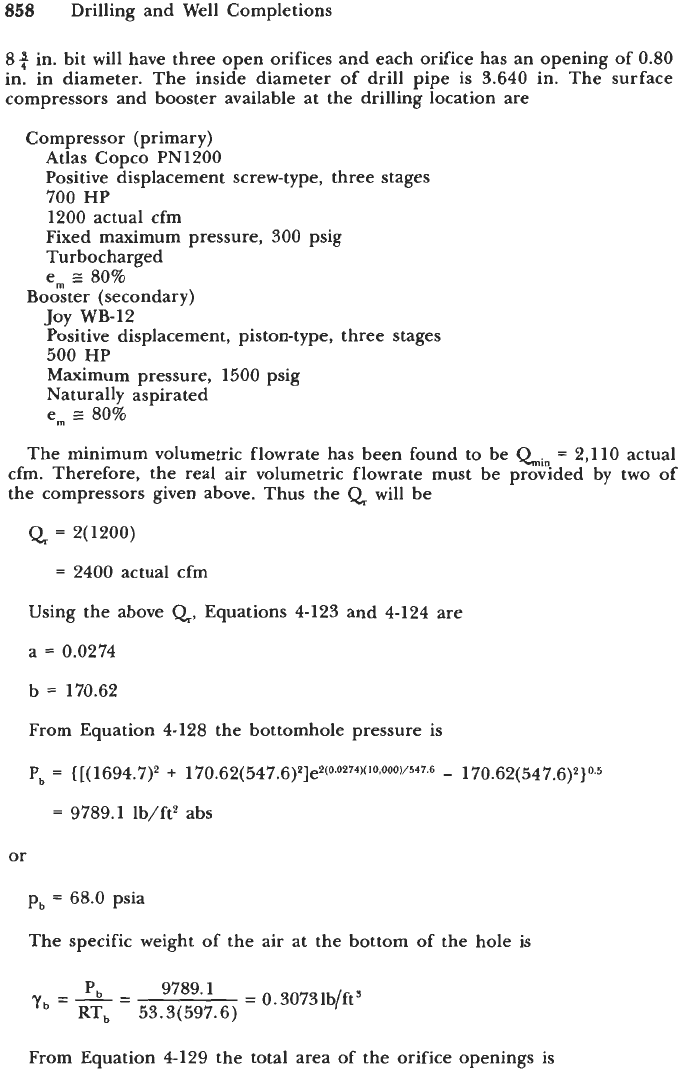
in. bit will have three open orifices and each orifice has an opening of
0.80
in. in diameter. The inside diameter
of
drill pipe is 3.640 in. The surface
compressors and booster available at the drilling location are
Compressor (primary)
Atlas Copco PN1200
Positive displacement screw-type, three stages
700 HP
1200 actual cfm
Fixed maximum pressure, 300 psig
Turbocharged
em 80%
Booster (secondary)
TOY
WB-12
-,
Positive displacement, piston-type, three stages
500 HP
Maximum pressure, 1500 psig
Naturally aspirated
em
E
80%
The minimum volumetric flowrate has been found to be
Qin
=
2,110 actual
cfm. Therefore, the real air volumetric flowrate must be provided by two of
the compressors given above. Thus the
Q
will be
Q
=
Z(1200)
=
2400 actual cfm
Using the above
Q,
Equations 4-123 and 4-124 are
a
=
0.0274
b
=
170.62
From Equation 4-128 the bottomhole pressure is
P,
=
{
[(
1694.7)2
+
170.62(547.6)2]e2~00274~('o~ooo~~547~6
-
170.62(547.6)2}0.5
=
9789.1 lb/ft2 abs
or
pb
=
68.0 psia
The specific weight of the air at the bottom of the hole is
9789'
=
0.3073 lb/ft3
y,=b_=
P
RT, 53.3(597.6)
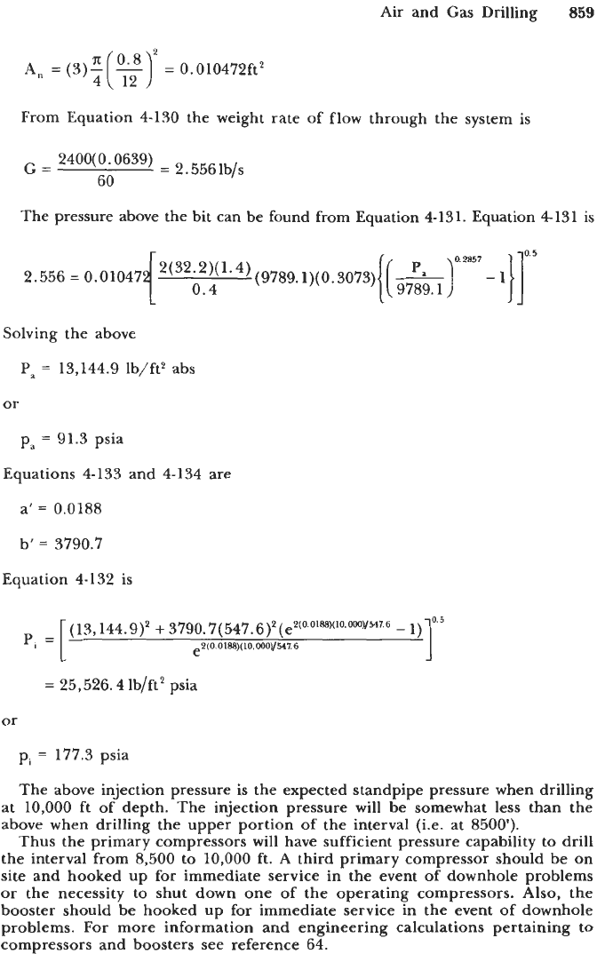
From Equation 4-129 the total area of the orifice openings is
Air and
Gas
Drilling
859
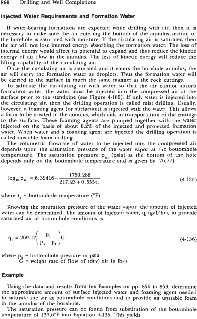
From Equation 4-130 the weight rate of flow through the system
is
The pressure above the bit can be found from Equation
4-131.
Equation
4-131
is
0.5
2.556
=
0.01047
~2(32.z)~1~4)(9789.~)(0.~073){
0.4
[ATm7-
9789.1
I}]
Solving the above
Pa
=
13,144.9 lb/ft2 abs
or
pa
=
91.3 psia
Equations 4-133 and 4134 are
a'
=
0.0188
b'
=
3790.7
Equation 4-132
is
13, 144.9)2
+
3790.7(547.6)2(e2~0-0'88~~'0~0"~547~6
-
1)
e2(0.
0188)(10.000)/547.6
=
25,526.4 lb/ft2 psia
or
pi
=
177.3 psia
The above injection pressure is the expected standpipe pressure when drilling
at 10,000 ft of depth. The injection pressure will be somewhat less than the
above when drilling the upper portion of the interval (Le. at
8500').
Thus the primary compressors will have sufficient pressure capability to drill
the interval from
8,500
to 10,000 ft. A third primary compressor should be
on
site and hooked up for immediate service in the event of downhole problems
or the necessity to shut down one
of
the operating compressors. Also, the
booster should be hooked up for immediate service in the event of downhole
problems.
For
more information and engineering calculations pertaining to
compressors and boosters see reference 64.
860
Drilling and Well Completions
Injected Water Requirements and Formation Water
If water-bearing formations are expected while drilling with air, then it is
necessary to make sure the air entering the bottom of the annulus section of
the borehole is saturated with moisture. If the circulating air is saturated then
the air will not lose internal energy absorbing the formation water. The loss of
internal energy would affect its potential to expand and thus reduce the kinetic
energy of air flow in the annulus. The loss of kinetic energy will reduce the
lifting capability of the circulating air.
Once the circulating air is saturated and it enters the borehole annulus, the
air will carry the formation water as droplets. Thus the formation water will
be carried to the surface in much the same manner as the rock cuttings.
To saturate the circulating air with water
so
that the air cannot absorb
formation water, the water must be injected into the compressed air at the
surface prior to the standpipe (see Figure
4-185).
If only water is injected into
the circulating air, then the drilling operation is called mist drilling. Usually,
however, a foaming agent (or surfactant) is injected with the water. This allows
a foam to be created in the annulus, which aids in transportation of the cuttings
to the surface. These foaming agents are pumped together with the water
injected on the basis of about
0.2%
of the injected and projected formation
water. When water and a foaming agent are injected the drilling operation is
called unstable foam drilling
The volumetric flowrate of water to be injected into the compressed air
depends upon the saturation pressure of the water vapor at the bottomhole
temperature. The saturation pressure p,,, (psia) at the bottom of the hole
depends only on the bottomhole temperature and is given by
[76,77].
1750.286
217.23
+
0.555tb
log,, psat
=
6.39416-
(4- 135)
where t,
=
bottomhole temperature (OF)
Knowing the saturation pressure of the water vapor, the amount of injected
water can be determined. The amount of injected water,
qi
(gal/hr), to provide
saturated air at bottomhole conditions is
qi
=
269.17
-
[
P.P.P.
1.
where pb
=
bottomhole pressure in psia
G
=
weight rate of flow of (dry) air in lb/s
Example
(4- 136)
Using the data and results from the Examples on pp.
856
to
859,
determine
the approximate amount of surface injected water and foaming agent needed
to saturate the air at bottomhole conditions and to provide an unstable foam
in the annulus
of
the borehole.
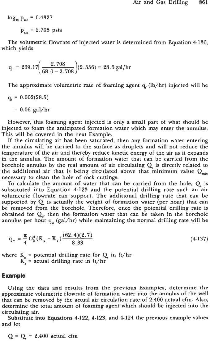
The saturation pressure can be found from substitution of the bottomhole
temperature of
137.6'F
into Equation
4-135.
This yields
Air and Gas Drilling
861
log,,p,,,
=
0.4327
p,,
=
2.708
psia
The volumetric flowrate of injected water is determined from Equation
4-136,
which yields
qi
=
269.17( 68.0-2.708
2*708
)(2.556)
=
28.5gallhr
The approximate volumetric rate of foaming agent
q,
(lb/hr) injected will be
q,
=
0.002(28.5)
=
0.06
gal/hr
However, this foaming agent injected is only a small part of what should be
injected to foam the anticipated formation water which may enter the annulus.
This will be covered in the next Example.
If the circulating air has been saturated, then any formation water entering
the annulus will be carried to the surface as droplets and will not reduce the
temperature of the
air
and
thereby reduce kinetic energy of the air as it expands
in the annulus. The amount of formation water that can be carried from the
borehole annulus by the real amount of air circulating
Q
is
directly related to
the additional air that is being circulated above that minimum value
Q.,
necessary to clean the hole
of
rock cuttings.
To calculate the amount of water that can be carried from the hole,
Q
is
substituted into Equation
4-123
and the potential drilling rate such an air
volumetric flowrate can support. The additional drilling rate that can be
supported by
Q
is actually the weight of formation water (per hour) that can
be removed from the borehole. Therefore, once the potential drilling rate is
obtained for
Q,
then the formation water that can be taken in the borehole
annulus per hour
q,
(gal/hr) while maintaining the normal drilling rate will be
x
(62.4)( 2.7)
8.33
qw
=-Di(K
4
p-k)
where
KP
=
potential drilling rate for
Q
in ft/hr
Ka
=
actual drilling rate in ft/hr
(4137)
Using the data and results from the previous Examples, determine the
approximate volumetric flowrate of formation water into the annulus of the well
that can be removed by the actual air circulation rate of
2,400
actual cfm. Also,
determine the total amount of foaming agent which should be injected into the
circulating air.
Substitute into Equations
4-122, 4123,
and
4124
the
previous example values
and
let
Q
=
Q
=
2,400
actual cfm
862
Drilling and Well Completions
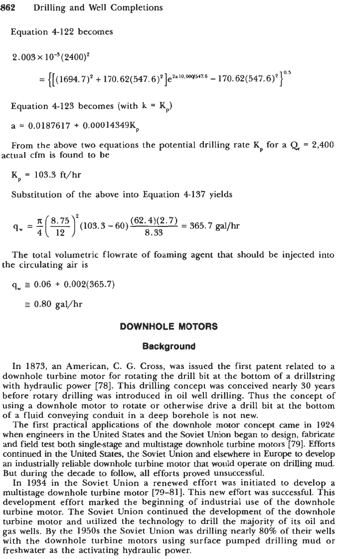
Equation
4-122
becomes
2.003
x
lo-'(
2400)'
=
([(1694.7)'
+
170.62(547.6)*]e'a~o~w54'~6
-
170.62(547.6)4}0'5
Equation
4-123
becomes (with
k
=
KP)
a
=
0.0187617
+
0.00014349Kp
From the above two equations the potential drilling rate
K,
for a
Q
=
2,400
actual cfm is found
to
be
K,
=
103.3
ft/hr
Substitution of the above into Equation
4-137
yields
(62*4)(2'7)
=
365.7
gal/hr
9,
=
-(-)
'
8'75
'(103.3-60)
8.33
4 12
The total volumetric flowrate of foaming agent that s--ould be injectel
the circulating
air
is
q,
I
0.06
+
0.002(365.7)
I
0.80
gal/hr
DOWNHOLE
MOTORS
into
Background
In
1873,
an American,
C.
G.
Cross,
was issued the first patent related to a
downhole turbine motor for rotating the drill bit at the bottom of a drillstring
with hydraulic power
[78].
This drilling concept was conceived nearly
30
years
before rotary drilling was introduced in oil well drilling. Thus the concept
of
using
a
downhole motor to rotate
or
otherwise drive a drill bit at the bottom
of
a fluid conveying conduit in a deep borehole is not new.
The first practical applications of the downhole motor concept came in
1924
when engineers in the United States and the Soviet Union began
to
design, fabricate
and
field test both singlestage and multistage downhole turbine motors
[79].
Efforts
continued in the United States, the Soviet Union and elsewhere in Europe to develop
an industrially reliable downhole turbine motor that would operate on drilling mud.
But during the decade to follow, all efforts proved unsuccessful.
In
1934
in the Soviet Union a renewed effort was initiated to develop a
multistage downhole turbine motor
[79-811.
This new effort was successful. This
development effort marked the beginning of industrial use of the downhole
turbine motor. The Soviet Union continued the development of the downhole
turbine motor and utilized the technology to drill the majority of its oil and
gas wells. By the
1950s
the Soviet Union was drilling nearly
80%
of their wells
with the downhole turbine motors using surface pumped drilling mud
or
freshwater as the activating hydraulic power.
Downhole Motors
863
In the late 19509, with the growing need in the United States and elsewhere in
the world for directional drilling capabilities, the drilling industry in the United
States and elsewhere began to reconsider the downhole turbine motor technology.
There are presently three service companies that offer downhole turbine motors for
drilling of oil and
gas
wells. These motors are now
used
extensively throughout the
world for directional drilling operations and for some straight-hole drilling operations.
The downhole turbine motors that are hydraulically operated have some
fundamental limitations. One of these is high rotary speed of the motor and
drill bit. The high rotary speeds limit the use of downhole turbine motors when
drilling with roller rock bits. The high speed of these direct drive motors
shortens the life of the roller rock bit.
In the 1980s in the United States an effort was initiated to develop a downhole
turbine motor that was activated by compressed air. This motor was provided
with a gear reducer transmission. This downhole pneumatic turbine has been
successfully field tested
[82].
The development of positive displacement downhole motors began in the late
1950s. The initial development was the result of a United States patent filed by
W.
Clark in 1957. This downhole motor was based on the original work of a
French engineer, RenC Monineau, and is classified as a helimotor. The motor
is actuated
by
drilling mud pumped from the surface. There are two other types
of positive displacement motors that have been used, or are at present in use
today: the vane motor and the reciprocating motor. However, by far the most
widely used positive displacement motor is the helimotor
[
79,831.
The initial work in the United States led to the highly successful single-lobe
helimotor. From the late 1950s until the late 1980s there have been
a
number
of other versions
of
the helimotor developed and fielded. In general, most
of
the recent development work in helimotors has centered around multilobe
motors. The higher the lobe system, the lower the speed of these direct drive
motors and the higher the operating torque.
There have been some efforts over the past three decades
to
develop positive
development vane motors and reciprocating motors for operation with drilling
mud as the actuating fluid. These efforts have not been successful.
In
the
early 1960s efforts were made in the United States to operate vane
motors and reciprocating motors with compressed air. The vane motors experi-
enced some limited test success but were not competitive in the market
of
that
day [84]. Out of these development efforts evolved the reciprocating (compressed)
air hammers that have been quite successful and are operated extensively in the
mining industry and have some limited application in the oil and gas industry
[85]. The air hammer is not a motor in the true sense of rotating equipment.
The reciprocating action of the air hammer provides a percussion effect on the
drill bit, the rotation of the bit to new rock face location is carried out by the
conventional rotation of the drill string.
In this section the design and the operational characteristics and procedures
of
the most frequently used downhole motors will be discussed. These are the
downhole turbine motor
and
the downhole positive displacement motor.
Turbine
Motors
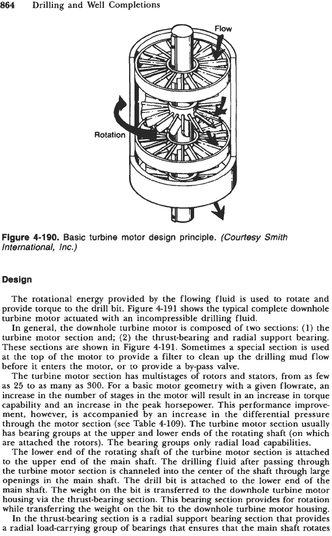
Figure
4-190
shows the typical rotor and stator configuration for a single stage
of a multistage downhole turbine motor section. The activating drilling mud or
freshwater is pumped at high velocity through the motor section, which, because
of the vane angle of each rotor and stator (which
is
a stage), causes the rotor to
rotate the shaft of the motor. The kinetic energy of the flowing drilling mud
is
converted through these rotor and stator stages into mechanical rotational energy.
864
Drilling and Well Completions
Figure
4-190.
Basic turbine motor design principle.
(Courtesy Smith
International, Inc.)
Design
The rotational energy provided by the flowing fluid is used to rotate and
provide torque to the drill bit. Figure
4191
shows the typical complete downhole
turbine motor actuated with an incompressible drilling fluid.
In general, the downhole turbine motor is composed of two sections:
(1)
the
turbine motor section and;
(2)
the thrust-bearing and radial support bearing.
These sections are shown in Figure
4-191.
Sometimes a special section is used
at the top of the motor to provide a filter to clean up the drilling mud flow
before it enters the motor,
or
to provide a by-pass valve.
The turbine motor section has multistages
of
rotors and stators, from as few
as
25
to as many as
300.
For a basic motor geometry with a given flowrate, an
increase in the number of stages in the motor will result in an increase in torque
capability and an increase in the peak horsepower. This performance improve-
ment, however, is accompanied by an increase in the differential pressure
through the motor section (see Table
4-109).
The turbine motor section usually
has bearing groups at the upper and lower ends of the rotating shaft (on which
are attached the rotors). The bearing groups only radial load capabilities.
The lower end of the rotating shaft of the turbine motor section is attached
to the upper end of the main shaft. The drilling fluid after passing through
the turbine motor section is channeled into the center of the shaft through large
openings in the main shaft. The drill bit is attached to the lower end of the
main shaft. The weight on the bit is transferred to the downhole turbine motor
housing via the thrust-bearing section. This bearing section provides for rotation
while transferring the weight on the bit to the downhole turbine motor housing.
In the thrust-bearing section is a radial support bearing section that provides
a radial load-carrying group of bearings that ensures that the main shaft rotates
