Linden D., Reddy T.B. (eds.) Handbook of batteries
Подождите немного. Документ загружается.

ZINC-CARBON BATTERIES 8.29
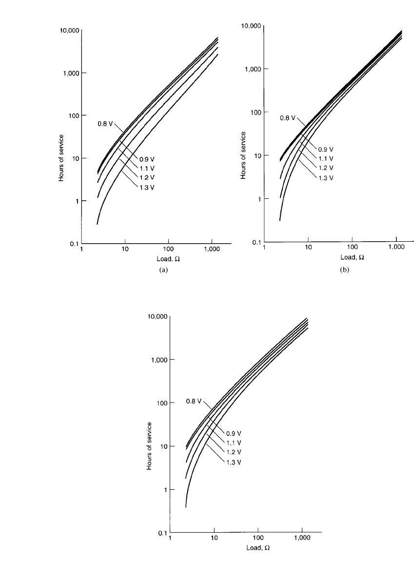
FIGURE 8.23 Discharge load vs. hours of service to different cutoff (end) voltages at 20⬚C, continuous
discharge. (a) Heavy duty D-size Leclanche´ battery. (b) Heavy duty D-size zinc-chloride battery.
FIGURE 8.24 Hours of service vs. discharge load to
different cutoff (end) voltages at 20⬚C, continuous dis-
charge. Extra heavy duty D-size zinc-chloride battery.
8.30 CHAPTER EIGHT
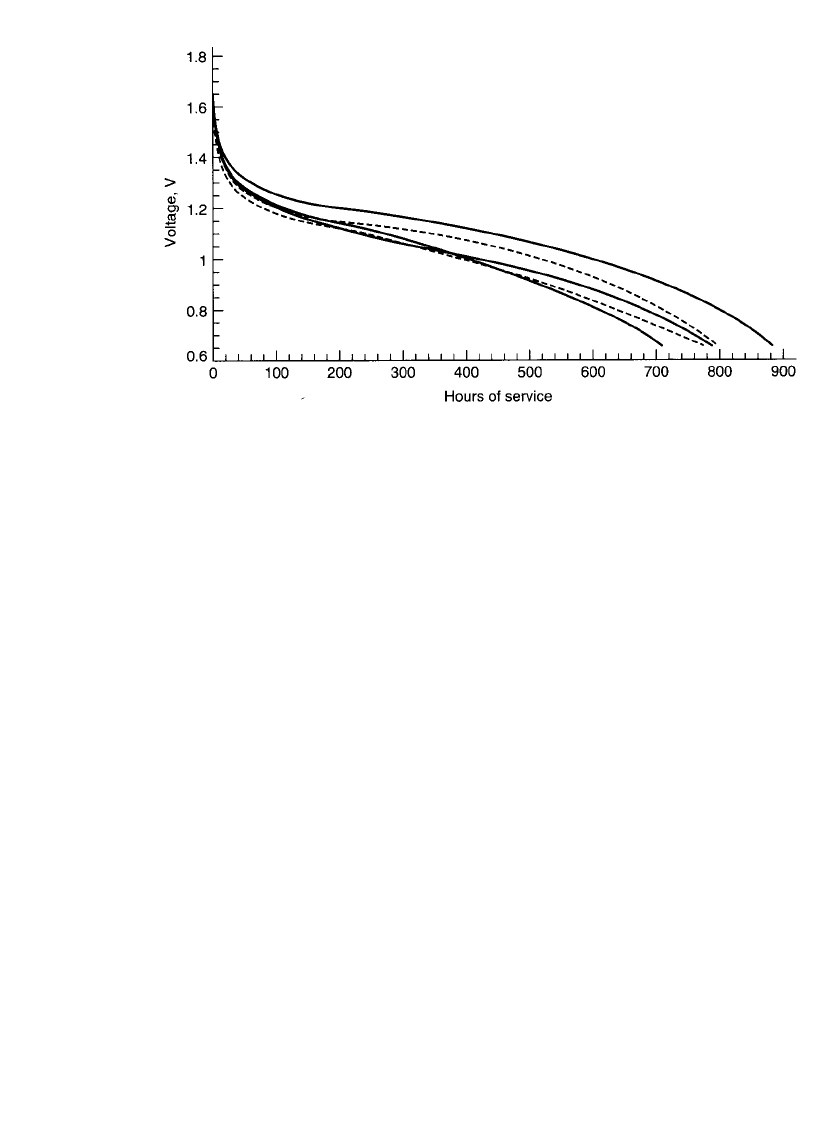
FIGURE 8.25 Comparison of general-purpose D-size zinc-carbon batteries of five different
manufacturers, discharged on the ANSI LIF test through 2.2 ohm load at 20⬚C.
8.6.6 Internal Resistance
Internal resistance R
in
is defined as the opposition or resistance to the flow of an electric
current within a cell or battery, i.e. the sum of the ionic and electronic resistances of the
cell components. Electronic resistance includes the resistance of the materials of construction:
metal covers, carbon rods, conductive cathode components, and so on. Ionic resistance en-
compasses factors resulting from the movement of ions within the cell. These include elec-
trolyte conductivity, ionic mobility, electrode porosity, electrode surface area, secondary
reactions, etc. These fall into the category of factors that affect the ionic resistance. These
factors are encompassed by the term polarization. Other considerations include battery size
and construction as well as temperature, age and depth of discharge.
Electronic Resistance. An approximation of the internal electronic resistance of a battery
can be made by determining the OCV and the peak flash current (I) using very low resistance
meters. The ammeter resistance should be low enough that the total circuit resistance does
not exceed 0.01 ohm and is no more than 10% of the cell’s internal resistance. The internal
electronic resistance is expressed as:
R
⫽ OCV/I
in
where: R
in
⫽ internal resistance expressed in ⍀
OCV ⫽ open circuit voltage
I
⫽ peak flash current A
A more accurate method of calculation is made using the voltage-drop method. In this
method, a small initial load is applied on the battery to stabilize the voltage. A load ap-
proximating the application load is then applied. The internal resistance is calculated by:
R
⫽ (V ⫺ V )R /V
in 1 2 L 2
where: R
in
⫽ internal resistance, ⍀
V
1
⫽ initial stabilized closed-circuit voltage, V
V
2
⫽ closed circuit voltage reading at the application load, VO
R
L
⫽ application load, ⍀

ZINC-CARBON BATTERIES 8.31
FIGURE 8.26 Voltage pulse / time profile illustra-
tion of curve shape and voltage components to cal-
culate internal resistance.
The application load time should be kept to a pulse of 5 to 50 ms to minimize effects
due to polarization. These methods measure the voltage loss due to the electrical resistance
component but do not take into account voltage losses due to polarization.
Ionic Resistance. The polarization effect is best illustrated by a trace of the Pulse /Time
profile as shown in Fig. 8.26. The total resistance (R
T
) is expressed using Ohm’s Law by
R
⫽ dR ⫽ dV/ dI
T
which also equals:
(V
⫺ V )/(I ⫺ I )
1212
where: V
1
and I
1
⫽ the voltage and current just prior to pulsing
V
2
and I
2
⫽ the voltage and current just prior to the pulse load removal
dV
3
⫽ total voltage drop shown
The internal resistance of the battery component is expressed as dV
1
and the polarization
effect component is the voltage drop dV
2
. Since some energy was removed by the pulse, a
more correct expression for the battery resistance is the voltage drop expressed by dV
4
.
Measurement of the battery voltage drop (dV
4
) is very difficult to capture, therefore the
pulse duration (dt) is minimized to reduce the polarization effect voltage drop (dV
2
). The
pulse duration is generally kept in the range of 5 to 50 milliseconds. For accurate and
repetitive results, it is recommended that duration times be kept constant by ‘‘read and hold’’
voltage measurements.
Since dV
2
is slightly greater than dV
1
, one can see that the resistance due to polarization
(R
p
) is greater than the internal resistance of the battery (R
ir
) by the formula
R
⫽ R ⫹ R
Tirp
Partial, light discharge or a light background load prior to the pulse and internal resistance
measurements provide equilibration for consistent measurements.
Table 8.6 shows the general relationship of flash current and internal resistance of the
more popular cell sizes.
Zinc-carbon batteries perform better on intermittent drains than continuous drains, largely
because of their ability to dissipate the effects of polarization. Factors that affect polarization
are identified earlier in this section. Resting between discharges allows the zinc surface to
‘‘depolarize.’’ One such effect is the dissipation of concentration polarization at the anode
surface. This effect is more pronounced as heavier drains and longer duty schedules are
8.32 CHAPTER EIGHT
TABLE 8.6 Flash Current and Internal Resistance for Various
Battery Sizes
Size
Typical maximum
flash current, A
LC* ZC*
Approximate internal
resistance,
⍀
LC ZC
N 2.5 ... 0.6 ...
AAA 3 4 0.4 0.35
AA 4 5 0.30 0.28
C 5 7 0.39 0.23
D 6 9 0.27 0.18
F 9 11 0.17 0.13
9V (battery) 0.6 0.8 5 4.5
*LC-Leclanche´, ZC-zinc chloride.
Source: Eveready Battery Engineering Data.
13
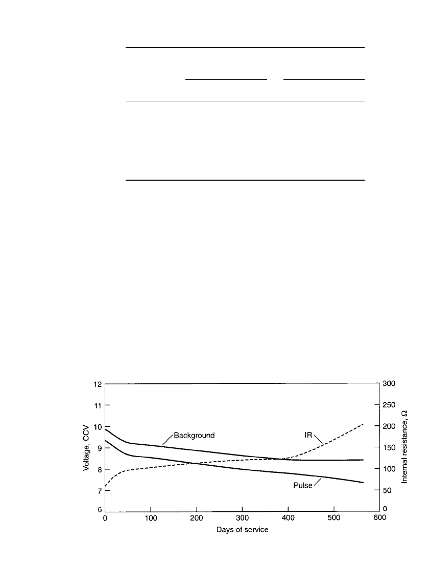
FIGURE 8.27 Comparison of voltage and internal resistance during discharge of a 9-V battery
on smoke detector test. Background load ⫽ 620,000 ohms continuous; pulse load ⫽ 1500 ohms
⫻ 10 ms every 40 s.
applied. The internal resistance of the zinc-chloride batteries is slightly lower than that of
the Leclanche´ batteries. This results in a smaller voltage drop for a given battery size.
The internal resistance of zinc-carbon batteries increases with the depth of discharge.
Some applications use this feature to establish low battery alarms to predict near end of
battery life situations (such as in the smoke detector). Fig. 8.27 shows the relative battery
internal resistance versus depth of discharge of a 9-V Leclanche´ battery.
One of the reasons for this increase in internal resistance is the cathode discharge reaction.
The porous cathode becomes progressively blocked with reaction products. In the case of
the Leclanche´ system, it is in the form of diammine-zinc chloride crystals; in the case of
the zinc-chloride system, it is in the form of zinc oxychloride crystals.
ZINC-CARBON BATTERIES 8.33
8.6.7 Effect of Temperature
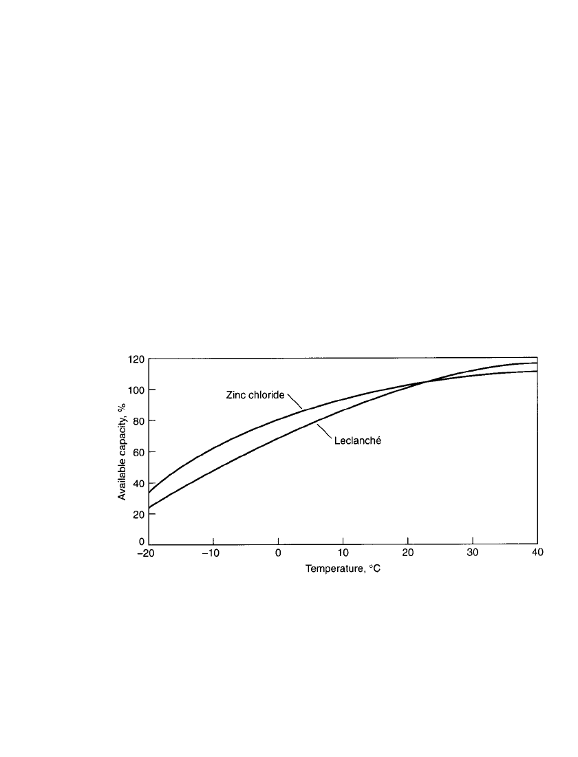
Zinc-carbon batteries operate best in a temperature range of 20⬚Cto30⬚C. The energy output
of the battery increases with higher operating temperatures, but prolonged exposure to high
temperatures (50⬚C and higher) will cause rapid deterioration. The capacity of the Leclanche´
battery falls off rapidly with decreasing temperatures, yielding no more than about 65%
capacity at 0
⬚C, and is essentially inoperative below ⫺ 20⬚C. Zinc-chloride batteries provide
an additional 15% capacity at 0
⬚C or 80% of room temperature capacity. The effects are
more pronounced at heavier current drains; a low current drain would tend to result in a
higher capacity at lower temperatures than a higher current drain (except for a beneficial
heating effect that may occur at the higher current drains).
The effect of temperature on the available capacity of zinc-carbon (Leclanche´ and zinc-
chloride systems) batteries is shown graphically in Fig. 8.28 for both general-purpose (am-
monium chloride electrolyte) and heavy-duty (zinc-chloride electrolyte) batteries. At ⫺20⬚C
typical zinc-chloride electrolytes (25% to 30% zinc-chloride by weight) turn to slush. Below
⫺25⬚C ice formation is likely. Under these conditions, it is not surprising that performance
is dramatically reduced. These data represent performance at flashlight-type current drains
(300 mA for a D-size cell). A lower current drain would result in a higher capacity than
shown. Additional characteristics of this D-size battery at various temperatures are listed in
Table 8.7.
FIGURE 8.28 Percentage of capacity available as a function of temperature, moderate-drain
radio-type discharge.
Special low temperature batteries were developed using low freezing-point electrolytes
and a design that minimizes internal cell resistance, but they did not achieve popularity due
to the superior overall performance of other types of primary batteries. For best operation,
at low ambient temperatures, the Leclanche´ battery should be kept warm by some appropriate
means. A vest battery worn under the user’s clothing, employing body heat to maintain it at
a satisfactory operating temperature was once used by the military to achieve reliable op-
eration at low temperatures.

8.34 CHAPTER EIGHT
TABLE 8.7 Temperature Effect on Internal Resistance
Battery size System*
Resistance,
⍀
⫺20⬚C0⬚C20⬚C45⬚C
Single cell batteries
AAA ZC 10 0.7 0.6 0.5
AA LC 5 0.8 0.5 0.4
AA ZC 5 0.8 0.5 0.4
C LC 2 0.8 0.5 0.4
C ZC 3 0.5 0.4 0.3
D LC 2 0.6 0.5 0.4
D ZC 2 0.4 0.3 0.2
Flat cell batteries
9 V LC 100 45.0 35.0 30.0
9 V ZC 100 45.0 35.0 30.0
Lantern batteries
6 V LC 10 1.0 0.9 0.7
6 V ZC 10 1.0 0.8 0.7
*LC ⫽ Leclanche´, ZC ⫽ Zinc chloride.
Source: Eveready Battery Engineering Data.
13
8.6.8 Service Life
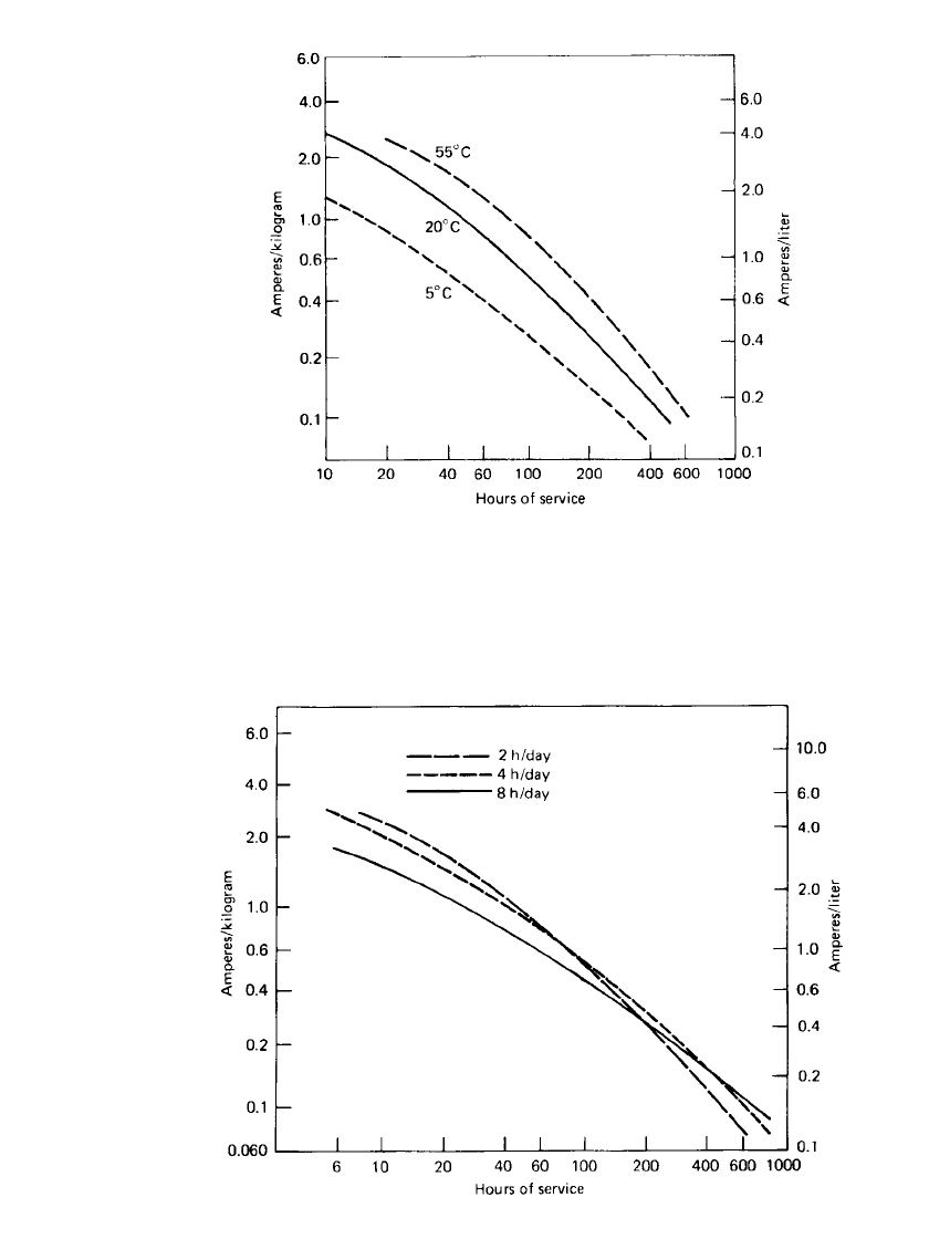
The service life of the Leclanche´ battery is summarized in Figs. 8.29 and 8.30, which plot
the service life at various loads and temperatures normalized for unit weight (amperes per
kilogram) and unit volume (amperes per liter). These curves are based on the performance
of a general-purpose battery at the average discharge current under several discharge modes.
These data can be used to approximate the service life of a given battery under particular
discharge conditions or to estimate the size and weight of a battery required to meet a specific
service requirement.
Manufacturers’ catalogs should be consulted for specific performance data in view of the
many cell formulations and discharge conditions. Table 8.8 presents typical data from a
manufacturer of two formulations of the AA-size battery.
ZINC-CARBON BATTERIES 8.35
FIGURE 8.29 Service hours for general-purpose zinc-carbon battery,
discharged 2 h / day to 0.9 V at 20⬚C.
FIGURE 8.30 Service hours for a general-purpose zinc-carbon battery discharged
intermittently to 0.9 V at 20⬚C.

8.36 CHAPTER EIGHT
TABLE 8.8 Manufacturer’s Data for AA-Size Zinc-Carbon Batteries
Schedule
Drain
@1.2 V,
mA
Load
⍀
Cutoff voltage V
1.3 1.2 1.1 1.0 0.9 0.8
Typical service of Eveready no. 1015 general-purpose battery
Hours
4 hr /day 28 mA 43 2 5 12 20 24 27
1 hr /day 120 mA 10 0.1 0.4 1.2 2.6 3.9 4.5
1 hr /day 308 mA 3.9 0.09 0.2 0.4 0.7 0.9 1.0
Pulses
15 sec /min / 667 mA 1.8 6 14 30 51 68 73
24 hr /day
(pulse)
Typical service of Eveready no. 1215 superheavy-duty battery
Hours
4 hr /day 28 mA 43 4 10 21 31 36 39
1 hr /day 120 mA 10 0.2 0.4 2.5 5.2 6.4 7.0
1 hr /day 308 mA 3.9 0.1 0.3 0.5 1.2 1.7 1.9
Pulses
15 sec /min / 667 mA 1.8 7 14 30 89 139 160
24 hr /day
(pulse)
Source: Eveready Battery Engineering Data.
12
8.6.9 Shelf-Life
Zinc-carbon batteries gradually lose capacity while idle. This deterioration is greater for
partially discharged batteries than for unused batteries and results from parasitic reactions
such as wasteful zinc corrosion, chemical side reactions, and moisture loss. The shelf-life or
rate of capacity loss is affected by the storage temperature. High temperatures accelerate the
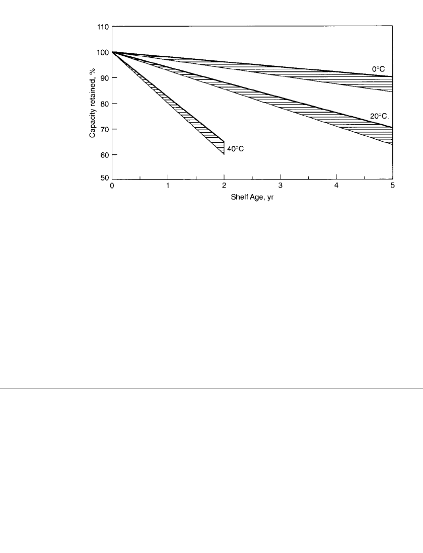
loss; low temperatures retard the loss. Refrigerated storage will increase the shelf-life. Figure
8.31 shows the retention of capacity of a zinc-carbon battery after storage at 40, 20, and
0
⬚C. The capacity retention of a zinc-chloride battery is higher than that of the Leclanche´
type because of the improved separators (coated paper separator-types), sealing systems and
other materials used in that design.
Leclanche´-type batteries, using the asphalt or pitch-type seals in conjunction with paste-
type separators, have the poorest capacity retention. Zinc-chloride batteries, using highly
crosslinked starch coated paper separators in conjunction with molded polypropylene or
polyethylene seals, provide the best retention.
ZINC-CARBON BATTERIES 8.37
FIGURE 8.31 Capacity retention after storage at 40⬚C, 20⬚C and 0⬚C for paper-lined plastic
seal zinc-chloride batteries.
Batteries stored at ⫺20⬚C are expected to retain approximately 80% to 90% of their initial
capacity after 10 years. Since low temperatures retard deterioration, storage at low temper-
atures is an advantageous method for preserving battery capacity. A storage temperature of
0
⬚C is very effective.
Freezing usually may not be harmful as long as there is no repeated cycling from high
to low temperatures. Use of case materials or seals with widely different coefficients of
expansion may lead to cracking. When batteries are removed from cold storage, they should
be allowed to reach room temperature in order to provide satisfactory performance. Moisture
condensation during warm-up should be prevented as this may cause electrical leakage or
short-circuiting.
8.7 SPECIAL DESIGNS
The zinc-carbon system is used in special designs to enhance particular performance char-
acteristics or for new or unique applications.
8.7.1 Flat-Pack Zinc/ Manganese Dioxide P-80 Battery
In the early 1970s, Polaroid introduced a new instant camera-film system, the SX-70. A
major innovation in that system was the inclusion of a battery in the film pack rather than
in the camera. The film pack contained a battery designed to provide enough energy for the
pictures in the pack. The concept was that the photographer would not have to be concerned
about the freshness of the battery as it was changed with each change of film.
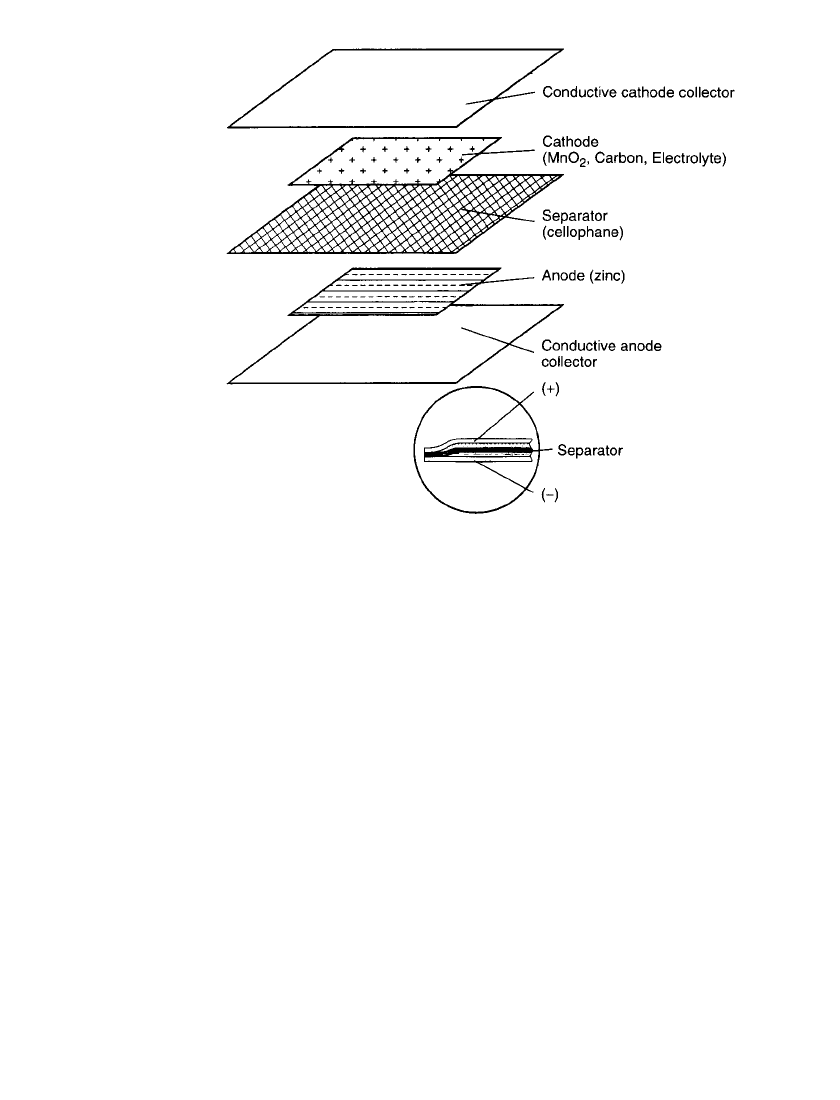
Battery Construction. The P-80 battery uses chemistry quite similar to Leclanche´ round
cells, although the shape is unique. Figure 8.32 details one cell (1.5 V). The electrode area
is approximately 5.1 cm
⫻ 5.1 cm. The zinc anode is coated on a conductive vinyl web.
8.38 CHAPTER EIGHT
FIGURE 8.32 Exploded view of a single cell from Polaroid P-80 battery
pack.
The manganese dioxide is mixed in a slurry which contains the electrolyte salts. The elec-
trolyte is mainly zinc chloride with some ammonium chloride. The anode and the cathode
are separated by a thin film of cellophane. The complete 6-volt battery has four cells. The
four identical cells are connected by vinyl frames to each other and the aluminum collector
plates. A special conductive coating allows the aluminum to bond to the plastic materials.
Battery Parameters. The key battery parameters of the flat battery are similar to those of
the cylindrical one. The flat configuration provides low resistance by virtue of the geometry.
The thin layers need to stay in intimate contact to maintain the low resistance and gassing
effects have to be minimized.
•
Open-Circuit (No-Load ) Voltage: The open-circuit voltage in this battery is dependent on
the manganese dioxide activity and the system pH. The cathode slurry is adjusted to a
constant pH to minimize battery to battery voltage variation. For example, the P-80 battery
is adjusted so the voltage is 6.40 V at 56 days and 6.30 V after 12 months of shelf storage.
•
Closed-Circuit (On-Load ) Voltage: The closed-circuit voltage is used as an indicator of
the battery’s capability to deliver energy at high currents. In the case of the P-80 battery,
a 1.63-A load is used since that is one of the operating requirements for the camera. The
closed-circuit voltage is measured at 55 milliseconds to minimize polarization effects. The
normal closed-circuit voltage is 5.58 V at 56 days and 5.35 V after 12 months of shelf
storage.
•
Internal Resistance and Voltage Drop (⌬V): The battery’s internal resistance is measured
by using the voltage drop or
⌬V at a given load for a specified pulse period. A major
contributor which effects
⌬V is the activity at the zinc surface which is dependent on both
