Lin S.D. Water and Wastewater Calculations Manual
Подождите немного. Документ загружается.

health factors have to be considered and evaluated. Those factors are
(US EPA, 1983, 1984b, 1988, 2000):
■
regulatory issues,
■
uses of constructed wetland,
■
changes in hydrologic regime,
■
cumulative impacts of inorganic and organic chemicals,
■
long-term biological effects,
■
mitigation/management issues, and
■
health/disease considerations.
Constructed wetland is relatively less regulated than a conventional
wastewater treatment system. It is a reliable, affordable, and operable
process for a small (less than 1 MGD or 3800 m
3
/d) wastewater treat-
ment plant. Constructed wetlands are also versatile, to be used either
as the primary means of secondary treatment or as a means of final pol-
ishing. Nowadays, the use of a constructed wetland is not uniformly
accepted as a proven technology or an emerging treatment technology
depending upon regulatory agencies. It has some degree of risks to
ecosystem and toxic compounds (still unknown). Also, the design process
is still empirical.
Sources of surface water and groundwater supplies have to be stud-
ied, including charge and discharge. Sequential changes of the hydrologic
regime in the wetland affect all aspects of the ecosystem. These changes
must be understood to determine nutrient cycle, sedimentation rates, ero-
sion patterns, plant and animal community compositions, and hydro-
logical budgets. These effects ultimately depend on the loading rate,
discharge quantity and quality, and size and type of receiving wetland.
Wetlands achieve good removal of nitrogen via denitrification.
Phosphorus removal is more variable. Wetlands have some ability to
assimilate organic and other compounds, and change soil chemistry. These
may cause the shift of dominant animal and plant species composition,
especially benthic invertebrate communities. Some metals do accumulate
within wetlands. Various physical and chemical parameters affect bioac-
cumulation. Refractory chemicals, such as surfactants, phenols, pesti-
cides, etc., are typically accumulated in wetlands. The long-term ecological
effects of these accumulation are less known.
Shifts in plant species composition and area distribution will change
in biomass production, detrital cycle habitat, aquatic food chain (web),
wildlife, animal, and fish species and population. Eventually these may
reduce water quality. The pathogens of concern in wetland treatment
system are bacteria, parasites, and viruses. Disease-carrying insect vec-
tors are potential risks.
Wastewater Engineering 865
Wetland-related recreational activities, such as canoeing, photogra-
phy, bird watching, camping, etc., should be evaluated. Cultivated crops,
pasture, hay crops, and silviculture are most likely not affected by con-
structed wetlands. Natural landscape (any unique areas, and open
spaces), archaeological sites, and historical sites have to be preserved.
The constructed wetlands should also be open for research and for public
educational purposes.
Mitigation measures should be taken to avoid impacts on wetland from
operation of conventional treatment facilities. The impacts include site
selection, construction of interceptors and pumping stations, discharge to
wetlands, included development, and increased human use of the area.
Free water surface wetlands. The differences between the two types of
wetlands were mentioned previously. Free water surface wetlands
closely resemble natural wetlands in appearance and function, with a
combination of open-water areas, emergent vegetation, varying water
depths, and other typical wetland features.
The main components of a FWS constructed wetland are sketched in
Fig. 6.63. A typical FWS constructed wetland consists of several com-
ponents that may be modified among various applications but retain
essentially the same features. These components include berms to
enclose the treatment cells, inlet structures that regulate and distrib-
ute influent wastewater evenly for optimum treatment, various combi-
nations of open-water areas and fully vegetated surface areas, and outlet
structures that complement the even distribution provided by inlet
structures and allow the adjustment of water levels within the treatment
cell. Shape, size, and complexity of design often are site characteristics
rather than preconceived design criteria.
Wetland hydrology. The wetland water balance for a FWS constructed
wetland is expressed as follows:
dV/dt ⫽ Q
i
⫹ Q
c
⫹ Q
sm
⫺ Q
b
⫺ Q
e
⫹ (P ⫹ ET ⫹ I )A (6.228)
where V ⫽ water volume or storage in wetland
t ⫽ time, hour (h) or day (d)
Q
i
⫽ wastewater inflow rate, m
3
/d or ft
3
/d
Q
c
⫽ catchment runoff rate, m
3
/d or ft
3
/d
Q
sm
⫽ snowmelt rate, m
3
/d or ft
3
/d
Q
b
⫽ berm loss rate, m
3
/d or ft
3
/d
Q
e
⫽ wetland outflow rate, m
3
/d or ft
3
/d
P ⫽ precipitation rate, m/d or ft/d
ET ⫽ evapotranspiration rate, m/d or ft/d
I ⫽ infiltration to groundwater, m/d or ft/d
A ⫽ wetland water surface area, m
2
or ft
2
866 Chapter 6
The impact of wet weather and snowmelt on the wastewater flow is
external to the water balance. Some of the terms in Eq. (6.228) may be
deemed insignificant and can be neglected. Q
b
and I can be neglected if
the wetland is lined with an impermeable layer; snowmelt is important
only in certain locations.
The wetland water volume V can be calculated by multiplying aver-
age water depth H by area A:
V ⫽ A ⫻ H (6.229)
Wetland porosity n or void fraction is the fraction of total volume
available through which water can flow. In a FWS wetland, vegetation,
settled solids, litter, and peat occupy water column. Wetland porosity
is difficult to measure in the field. For design purpose, it is recom-
mended to have a porosity value of 0.65 to 0.75 for fully vegetated
zones; 1.0 for wetland open-water zones; and around 0.88 for an aver-
age value.
The average wastewater flow rate is the mean of the FWS influent Q
i
and effluent Q
e
flow rates. It is expressed as:
Q
ave
⫽ (Q
i
⫹ Q
e
)/2 (6.230)
The nominal hydraulic retention time (HRT) is defined as the ratio
of useable wetland water volume to the average flow rate. The theolog-
ical hydraulic retention time t is calculated as:
t ⫽ V ⫻ n/Q
ave
(6.231)
The hydraulic loading rate (q, in m/h or m
3
/m
2
/h) is the volumetric flow
rate divided by the wetland surface area and represents the depth of
water distributed to the wetland surface over a specific time interval.
The hydraulic loading rate can be computed as:
q ⫽ Q
i
/A (6.232)
Manning’s equation (Eq. (4.22b)), which defines flow in open channel,
is adopted to estimate head loss in FWS wetland as follows:
S
1/2
⫽ v/(1/n)(H
2/3
) (6.233)
where S ⫽ hydraulic gradient or slope of water surface
v ⫽ average flow velocity, m/s or ft/s
n ⫽ Manning’s resistance coefficient, s/m
1/3
H ⫽ average wetland depth, m or ft
A typical slope is of 1 in 10,000, or 1 cm in 100 m. The coefficient n is
a function of water depth and the resistance of specific surface. The
Wastewater Engineering 867
range of n values in wetland are 0.3 to 1.1 s/m
1/3
. Since multiple cells
are recommended as good design practice to minimize short-circuiting
and to maximize treatment performance, for most applications where
aspect ratios (length/width) are within suggested limits of 3 : 1 to 5 : 1,
or even larger.
Design considerations. The design models and methods have been used
to predict the fate of BOD, TSS, TN, HN
4
, NO
3
, TP, and FCs in a FWS
system. The performances of the above parameters in both FWS and
VSB wetlands are discussed in detail elsewhere (US EPA, 2000). FWS
constructed wetlands have usually been modeled as attached growth bio-
logical reactors, in which the plants and detrital material uniformly
occupy the entire volume of the wetland.
For the purpose of providing secondary (BOD ⫽ TSS ⫽ 30 mg/L) and
advanced secondary treatment of municipal wastewaters, no particular
equations alone are able to accurately predict the performance of a mul-
tizone FWS constructed wetland. Even if they could be calibrated “to fit”
a specific set of data, their nondeterministic basis belies their ability to
fit other circumstances of operation.
The areal loading rate (ALR) method specifies a maximum loading
rate per unit area for a given constituent. These methods are common
in the design of oxidation ponds and land treatment systems. The ALR
can be used to give both planning level and final design sizing esti-
mates for FWS systems from projected pollutant mass loads. For exam-
ple, knowing the areal BOD loading rate, the expected BOD effluent
concentration can be estimated or compared to the long-term average
performance data of other well-documented, full-scale operating sys-
tems. The ALR can be described as:
ALR ⫽ Q
i
C
i
/A (6.234)
where C
i
⫽ influent concentration of pollutant, mg/L
Q
i
⫽ incoming flow, m
3
/d or ft
3
/d
A ⫽ total area of FWS, ha or acre
The ALR method does not always correlate to a reasonable design
basis, especially with regard to nutrients and pathogen removal; other
mechanistic explanations are necessary. However, if typical municipal
wastewaters are to be treated that have total and filtered pollutant
fractionation reasonably consistent from site to site, a rational design
approach can be deduced for those parameters which can be removed
during the enhanced flocculation/sedimentation that occurs in the ini-
tial fully vegetated zone of a FWS constructed wetland. Therefore, based
on Figs. 6.63 and 6.65, the following areal loading rates can be used for
this initial zone (zone 1) of the FWS:
868 Chapter 6

Zone 1 areal loading rate
Parameter Effluent concentration, mg/L kg/ha ⭈ d lb/acre ⭈ d
BOD 30 40 35.7
TSS 30 30 26.8
The relative areal loadings imply that unless the pretreatment
processes were to have a BOD concentration of greater than 1.3 times
the TSS concentration, the latter would be the critical loading rate for
the fully vegetated zone if secondary standards are to be met by a fully
vegetated FWS system.
If the FWS system were to have significant open areas between fully
vegetated zones, a better effluent quality could be attained at areal
loadings, based on the entire FWS system area.
Areal loading rate
Parameter Effluent concentration, mg/L kg/ha ⭈ d lb/acre ⭈ d
BOD 30 60 53.6
BOD ⬍ 20 45 40.2
TSS 30 50 44.6
TSS ⬍ 20 30 26.8
The loading rates in the above table are based on the entire system
area, not just zone 1. Therefore, with open-water zones that provide
aerobic transformations and removal opportunities, a better effluent
quality is achievable than with a fully vegetated FWS system. It is rec-
ommended that the minimum HRT at the maximum monthly flow in
both zones 1 and 3 (fully vegetated) be 2 days. The water depth should
be 0.6 to 0.9 m. There are insufficient data at this time to eliminate
the need to provide effluent disinfection. The open-water zones would
attract wildlife to a great degree, and would be affected by their
activities.
A FWS constructed wetland is most likely to treat effluent from a
stabilization or oxidation pond, or from primary-treated (settled) munic-
ipal wastewater. After the designer determines overall size of the FWS
system from these BOD and TSS areal loading rates, the designer can
return to evaluate the fate of other constituents. TSS removal and
removal of associated BOD, organic N and P, metals, etc. occur in the
initial portion of the cell (Fig. 6.65), while the subsequent zones can
impact certain soluble constituents. Given sufficient dissolved oxygen
in open (unvegetated) areas, soluble BOD removal and nitrification of
ammonia can occur. If sufficient oxygen is present, soluble BOD can be
removed very slowly by anaerobic processes.
Wastewater Engineering 869
In zone 2, which is primarily open-water, the natural reaeration
processes are supplemented by submerged macrophytes during day-
light periods to elevate dissolved oxygen in order to oxidize carbona-
ceous compounds (BOD) to sufficiently low levels to facilitate
nitrification of the NH
4
-N to NO
3
-N. These processes require large
amounts of oxygen and time in a passive system (no mechanical assis-
tance). The maximum HRT in zone 2 is generally limited to about 2 to
3 days before unwanted algal blooms occur. The water depth should
be 1.2 to 1.5 m. Then, there are three cells in each train and at least
two trains (unless very small system). Therefore, more than one open
zone may be required to complete these reactions. If so, the result
would be a five (or more) zone design; because each open zone is fol-
lowed by a fully vegetated zone. The reactions in zone 2 are essentially
the same as in a facultative lagoon. Therefore, the first-order equation
for FC die-off could be applied as an approximation, along with its tem-
perature dependency as:
(6.235)
where C
i
, C
e
⫽ influent and effluent FC concentrations, respectively,
cfu/100 mL
N ⫽ number of open-water zones in the FWS
t ⫽ HRT, days
K
f
⫽ FC removal rate constant, per day
⫽ 2.6 (1.19)
T⫺20
T ⫽ temperature, ⬚C
C
e
C
i
5
1
s1 1 tK
f
d
N
870 Chapter 6
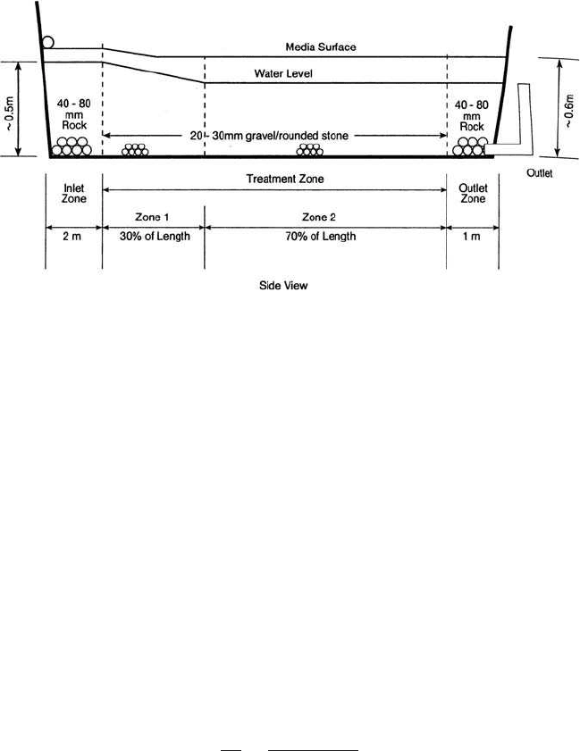
Figure 6.65 Proposed zones in a vegetated submerged bed system (source: US EPA 2001).

BOD removal in the open-water zone should also follow existing equa-
tions such as:
(6.236)
where C
i
, C
e
⫽ influent and effluent BOD, respectively, mg/L
K
b
⫽ specific BOD removal rate constant, per day
⫽ 0.15 (1.04)
T⫺20
The reduction in wetland volume due to settled solids, living plants,
and plant detritus can be significant over the long term. The rate of accu-
mulation of settled suspended solids is a function of the water temper-
ature, the mass of influent TSS, the effectiveness of TSS removal, the
decay rate of the volatile fraction of the TSS, and the settled TSS mass
that is nonvolatile. The plant detritus buildup is a function of the stand-
ing crop and the decay rate of the plant detritus. Accumulation for emer-
gent vegetated areas of the Arcata enhancement wetlands was measured
to be approximately 12 mm/yr of detritus on the bottom due to plant
breakdown and 12 to 25 mm/yr of litter forming a thatch on the surface
(Kadlecik, 1996). The volume of the living plants, specifically the volume
of the emergent plants, ranged from 0.005 m
3
/m
2
(low stem density,
water depth of 0.3 m) to 0.078 m
3
/m
2
(high stem density, water depth of
0.75 m). This accumulation is more or less constant from year to year
as the wetland matures. The total volume reduction under the initial
vegetated zone can be estimated using a mass balance equation:
V
r
⫽ (V
ss
t ⫹ V
d
t) A (6.237)
where V
r
⫽ volume reduction over the period of analysis, m
3
V
ss
⫽ volume reduction due to nonvolatile TSS and
nondegradable volatile TSS accumulation, m
3
/ha ⭈ yr
V
d
⫽ volume reduction due to nonvolatile detrital accumulation
as a function of annual production, m
3
/ha ⭈ yr
A ⫽ fully vegetated wetland area, ha
t ⫽ period of analysis, year
Example 1: A reasonable default value for V
ss
when treating raw wastewater
in lagoons ranges from 200 to 400 m
3
/ha ⭈ yr (2 to 4 cm/yr). Therefore, a con-
servative default value of 150 m
3
/ha ⭈ yr can be used. The loss of volume per
hectare over an 8-year period for a 1-ha fully vegetated FWS wetland zone with
a depth of 0.75 m can be estimated by use of this equation. One hundred per-
cent coverage of emergent vegetation was measured to contribute 116 m
3
/ ha ⭈ yr
of bottom detritus, and 104 m
3
/ha ⭈ yr of surface litter with a standing crop
volume of 360 m
3
/ha. Estimate the loss of volume per hectare over an 8-year
period for a 1-ha fully vegetated FWS wetland zone with a depth of 0.75 m.
C
e
C
i
5
1
s1 1 tK
b
d
N
Wastewater Engineering 871
solution:
V
d
⫽ 116 m
3
/ha ⭈ yr ⫹ 104 m
3
/ha ⭈ yr ⫽ 220 m
3
/ha ⭈ yr
Using Eq. (6.237):
V
r
⫽ (V
ss
t ⫹ V
d
t) A
⫽ [150 m
3
/ha ⭈ yr ⫻ 8 years ⫹ 220 m
3
/ha ⭈ yr ⫻ 8 years] ⫻ 1 ha
⫽ 2960 m
3
Example 2: Design a FWS constructed wetland to treat lagoon effluent to
meet a monthly average 30 mg/L of both BOD and TSS discharge standards.
Given the design conditions: population ⫽ 42,000 people; the average annual
design flow Q
ave
,
Q
ave
⫽ 15,900 m
3
/d (4.2 MGD); Q
max
⫽ 2Q
ave
⫽ 31,800 m
3
/d
At Q
ave
: the influent BOD ⫽ 55 mg/L, while the average TSS ⫽ 66 mg/L; at the
maximum monthly flow: the BOD ⫽ 38 mg/L and TSS ⫽ 32 mg/L, respec-
tively; the maximum ALRs are 40 kg BOD/ha ⭈ d and 30 kg TSS/ha ⭈ d for a
single cell; and the maximum ALRs are 60 kg BOD/ha ⭈ d and 50 kg TSS/ha ⭈ d
for with open areas.
solution:
Step 1a. Determine the total area required under the critical condition for
a single cell
Rearranging Eq. (6.234),
A ⫽ Q
i
C
i
/ALR
For BOD yields: at Q
ave
A ⫽ 15,900 m
3
/d ⫻ 1000 L/m
3
⫻ 55 mg/L/(40 kg/ha ⭈ d ⫻ 10
6
mg/kg)
⫽ 21.9 ha
at Q
max
A ⫽ 31,800 ⫻1000 ⫻ 38/(40 ⫻ 10
6
) ⫽ 30.2 (ha)
For TSS yields: at Q
ave
A ⫽ 15,900 ⫻ 1000 ⫻ 66/(30 ⫻ 10
6
) ⫽ 35.0 (ha)
at Q
ave
A ⫽ 31,800 ⫻ 1000 ⫻ 32/(30 ⫻ 10
6
) ⫽ 33.9 (ha)
872 Chapter 6
Thus, the limiting factor is the TSS loading at average flow conditions where
35.0 ha are required to meet the secondary effluent standards using a fully
vegetated single-zone FWS wetland system.
Step 1b. Similarly, recalculate the total area required from the higher
ALRs for the FWS system with significant open areas between fully vege-
tated zones
For BOD yields: at Q
ave
A ⫽ 15,900 m
3
/d ⫻1000 L/m
3
⫻ 55 mg/L/(60 kg/ha ⭈ d ⫻10
6
mg/kg)
⫽ 14.6 ha
at Q
max
A ⫽ 31,800 ⫻ 1000 ⫻ 38/(60 ⫻ 10
6
) ⫽ 20.1 (ha)
For TSS yields: at Q
ave
A ⫽ 15,900 ⫻ 1000 ⫻ 66/(50 ⫻ 10
6
) ⫽ 21.0 (ha)
at Q
ave
A ⫽ 31,800 ⫻ 1000 ⫻ 32/(50 ⫻ 10
6
) ⫽ 20.4 (ha)
The limiting condition is still the TSS areal loading at the average flow con-
ditions. But, the total area requirement is only 21.0 ha instead of 35.0 ha.
Step 2. Compute the theoretical HRT assuming H ⫽ 0.6 and n ⫽ 0.75 in the
vegetative zones (1 and 3) and H ⫽ 1.3 m and n ⫽ 1.0 in the open zone 2. The
combined average depth is estimated of 0.84 m and an average n ⫽ 0.82. Using
Eq. (6.231), for Q
ave
t ⫽ V ⫻ n/Q
ave
⫽ A ⫻ H ⫻ n/Q
ave
⫽ 21 ha ⫻ 10,000 m
2
/ha ⫻ 0.84 m ⫻ 0.82/15,900 m
3
/d
⫽ 9.1 days
for Q
max
t ⫽ 21 ⫻ 10000 ⫻ 0.84 ⫻ 0.82/31,800 ⫽ 4.55 days
Note: The above implies that at Q
max
, the HRT may not be adequate for the
necessary treatment mechanisms to perform. For zone 1, the minimum HRT
at Q
max
should be at least 2 days with 4 days at Q
ave
. For zone 2, there is an
upper limit that depends on climate and temperature. For most US conditions,
a maximum HRT of 2 to 3 days should avoid algal blooms (a load to zone 3);
although the longer the HRT, the better the removal for soluble organics,
ammonia-N, and bacteria. Zone 3 should have the same considerations as
zone 1. It also provides denitrification.
Therefore, the minimum HRT at Q
max
is 6 (2 ⫹ 2 ⫹ 2) days, and 12 days
at Q
ave
as in this example.
Wastewater Engineering 873
Step 3. Use t ⫽ 12 days to determine the area A required at Q
ave
Substituting Eq. (6.229) into Eq. (6.231) and rearranging it,
A ⫽ t Q/nH⫽ 12 days ⫻ 15,900 m
3
/d/(0.82 ⫻ 0.84 m ⫻ 10,000 m
2
/ha)
⫽ 27.7 ha (say 28 ha ⫽ 69 acres)
Applying the normal additional area for the inlet, buffers, and outlet of a factor
ranging from 1.25 to 1.40, the total area required for the FWS wetland is
35 ha (28 ha ⫻ 1.25) or 86.5 acres.
Step 4. Configuration: The FWS system should be designed at least with
two parallel treatment trains of a minimum of three cells in each. Say for 2
trains, for this example, the area of each train would be 14 ha ⫽ 140,000 m
2
.
The shapes of the system can be squares, rectangles, polygons, ovals, kidney
shapes, and crescent shapes. Let us select rectangles. The optimum aspect
ratio, or average length L to average width W, ranges 3 : 1 to 5 : 1. If the
ratio ≥ 10, we may need to calculate backwater curves. Using L : W ⫽ 4 : 1,
then 4W
2
⫽ 140,000 m
2
. We obtain W ⫽ 187 m and L ⫽ 748 m (only for 3 cells).
Say each cell has 250 m in length. By adding 25% of length for the inlet and
outlet zones, the total length for the system is 937 m.
In summary, the FWS system includes 2 trains. Each train has 187-m
width and contains inlet zones, 3 treatment zones (1, 2, and 3), and outlet
zones. The lengths of each zone respectively are of 87, 250, 250, 250, and 90 m.
The depths of each zone respectively are of 1.0, 0.6, 1.3, 0.6, and 0.6 m.
Note: To effectively minimize short-circuiting with baffles in the FWS
system, the inlet/outlet structures should be designed for uniform distribu-
tion of inflow across the entire width of the wetland inlet and uniform col-
lection of effluent across the entire wetland outlet width. An inlet-settling
structure may be needed if there is high TSS in the influent. The outlet weir
loading should be ⱕ 200 m
3
/m ⭈ d.
Multiple cells allow for redistribution of the primary cell effluent in the sub-
sequent cell that reduces short-circuiting. Flexible intercell piping will facil-
itate maintenance without a major reduction in the necessary HRT to produce
satisfactory effluent quality. Aspect ratios of the cells should be greater than
3:1 and adapted to the site contours and restrictions. Additional treatment
will likely be required alter the FWS system to meet fecal coliform and dis-
solved oxygen permit requirements.
Example 3: Use the same design conditions as Example 2. Design a FWS
wetland system to meet 20-20 (both BOD and TSS ≤ 20 mg/L) effluent stan-
dards, i.e. to meet this effluent quality, an open-water zone is required in the
FWS wetland. The maximum ALRs are 45-kg BOD/ha ⭈ d and 30-kg TSS/
ha ⭈ d for the system.
solution:
Step 1. Compute areas required at average and maximum flows as in
Example 2
874 Chapter 6