Lewis R.I. Turbomachinery Performance Analysis
Подождите немного. Документ загружается.

104
Performance analysis for axial compressors and fans
As can be seen from Fig. 4.9 the rotor blades for this fan are both highly staggered
and widely spaced. The stator on the other hand is more typical of an axial compressor
blade row. The numerical example which follows invites the reader to complete the
detailed design of this fan for himself.
Example 4.4
Problem
The mean radius section of an axial fan comprising rotor plus stator is to operate
with duty ~b = 0.5, ~ = 0.3. Select suitable rotor and stator cascades making use of
the program CASCADE. What fraction of the stage pressure rise would be lost if
we dispensed with the stator?
Solution
First of all assemble velocity triangle data. From Eqns (4.43) and (4.47)
a2 = tan-l(0.3/0.5) = 30.964 ~
a3 = 0.0 ~
fll =
tan-l(1/0.5) = 63.435 ~
/32 = tan -1 {(1- 0.3)/0.5} = 54.462 ~
(t/l)R
= 2.0081
(t/l)s
= 1.3897
By trial and error use of program CASCADE the following stagger and camber angles
were obtained using the C4 profile and circular arc camber for the given
t/l
values
above:
Blade row h ~ 0 ~ Shock-free data
Inlet angle Outlet angle
Rotor 58.2 37 63.44 54.40
Stator 14.65 57.64 30.92 0.00
The actual blade geometry for this fan is shown in Fig. 4.9 which illustrates the
typical high stagger and wide spacing of the rotor. The fraction of pressure rise
sacrificed if we dispense with the stator would be
lpc2o2 l (co2/u)e 1
(Apo)stator 2
(Apo)fan - (Apo)fan if/
2
~=0.15
Alternatively from the definition of reaction Eqn (4.5), using also Eqn (4.41),
(aPo)stator
(Apo)fan
= 1-R = 1- (1-1~) = 0.15
4.8 Influence of pitch~chord ratio upon the deflection properties of cascades
105
80
P2
60
40
20
t/I = 1.0
t/I
=
2.0081
0 20 4(
J
i
Design
duty
pl =
65.44 ~
p 2 = 54.46~
60 pt 80
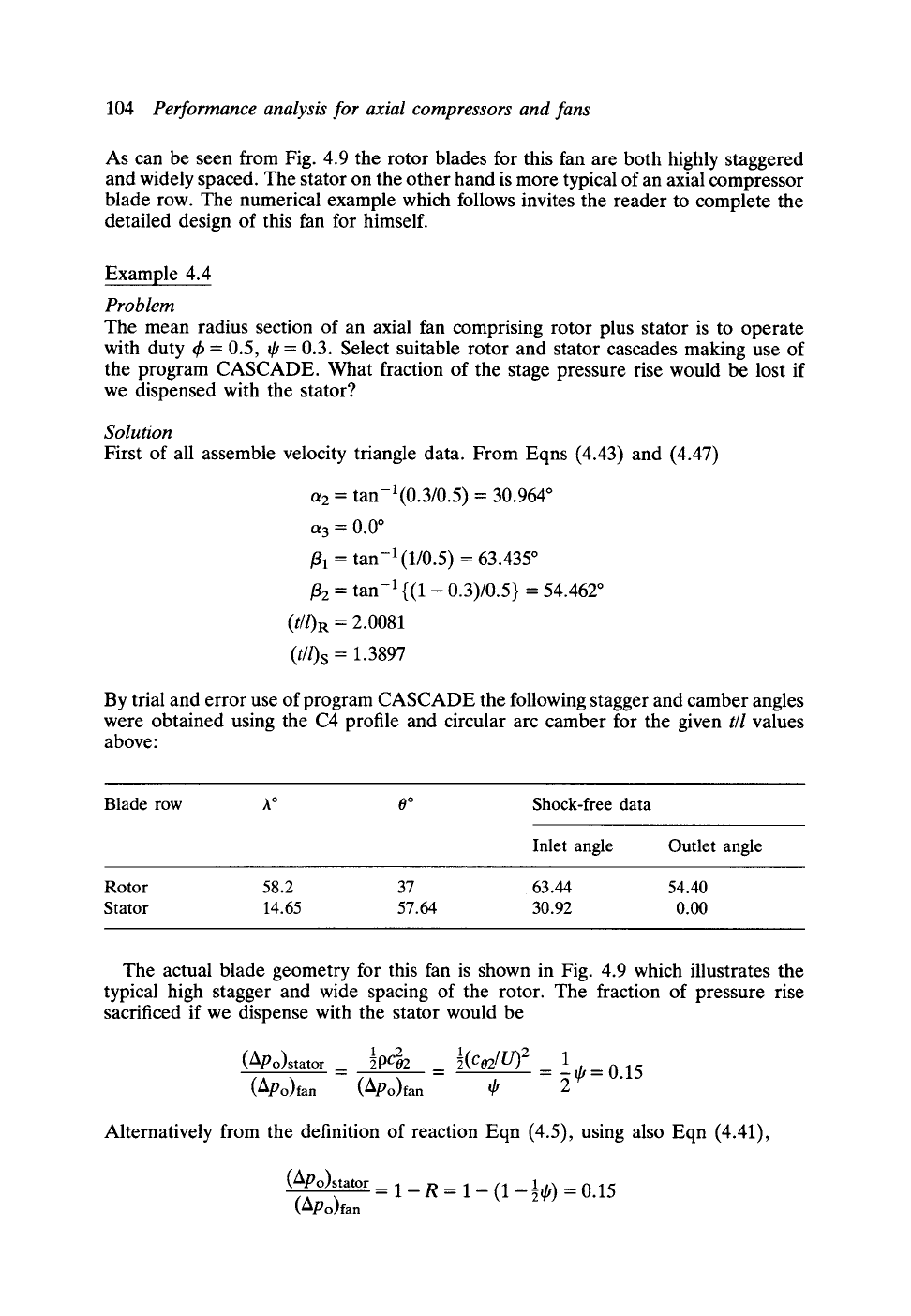
Fig.
4.10 Variation of outlet angle /32 with inlet angle
~1
for two axial fan cascades of different
pitch/chord ratios
Thus the stator accounts for 15% of the stage pressure rise, a small but significant
amount.
4.8
Influence of pitch/chord ratio upon the deflection
properties of cascades and upon the ~-~
characteristics of an axial fan
In the example just considered the aerodynamically acceptable rotor blade spacing,
corresponding to a slightly conservative diffusion factor of 0.5, was quite large,
namely
t/l
= 2.008. For cascades with
t/l
in excess of 1.0 the variation of outlet angle
/32 with inlet angle/31 is quite marked as illustrated by Fig. 4.10.
Curves of/32 versus/31 are shown here for two cascades selected to deliver the
prescribed duty of Example 4.4 with shock-free inflow but with completely different
pitch/chord ratios, namely
t/l
= 2.008 and
t/l
= 1.0. The first of these has the geometry
previously selected and tabulated above. The cascade parameters for the second
cascade have the values
t/l
= 1.0 and A = 56.7 ~ again using the C4 profile thickness
distributed on a circular arc camber line with O = 18 ~ Although one of these designs
would have double the number of blades of the other and thus be aerodynamically
very conservative, it would certainly do the job of matching and delivering the design
duty velocity triangle requirements,/31 = 63.44 ~ /32 = 54.46 ~ On the other hand if
we were to vary the inlet angle/31 over some range such as that shown in Fig. 4.10
the outlet angle/32 and fluid deflection e =/31-/32 would differ dramatically away
from the design duty. As a simple rule of thumb it can be assumed that for
t/l
< 1.0
the outlet angle/32 would remain almost constant over a range of/31 values due to
the fact that adjacent blades of the cascade now form distinct passages which are able
to guide the fluid more strongly. For
t/l >>
1.0 on the other hand the blades are tending
to act as separate aerofoils so widely spaced that mutual aerodynamic interference
becomes less significant.
This leads us to another very important consideration in fan design, namely the
off-design performance. In service conditions fans frequently have to be operated
106
Performance analysis for axial compressors and fans
0.8-
o.7- ~~ f/I- 1.0
0.6-
o.3- f/I - 2.0081 9
0.2-
0.1 "
Design
duly
jJ
\
O"
0.1 0.2 0.3 0.4 0.5 0.6 0.7 0.8
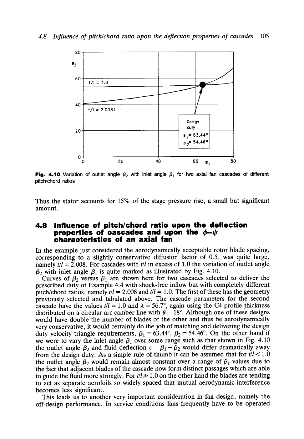
Fig. 4.11
Predicted 'frictionless' characteristics for two fan cascades with different pitch/chord
ratios
but the
same design duty
away from the design (~b, q0 duty. For example, it may be cheap and convenient for
us to select a constant speed electric drive for a simple ventilation fan and there are
indeed many such installations. Any change in the flow coefficient ~b due to variations
of the system resistance will then result also in a change of work coefficient qJ. To
illustrate the outcome, 4~--qJ characteristics for the two fan designs under consideration
are shown in Fig. 4.11. These are styled 'frictionless' characteristics since the
predictions are based on ideal frictionless fluid theory. Nevertheless, they serve to
illustrate the trends related to pitch/chord ratio. For the closely pitched blade row
with
t/l
= 1.0, the slope of the 4~-qJ characteristic is very much greater due to rotor
relative outflow angle being held almost constant at/32 = 54.46 ~ over the whole range
of flows 0.2 < 4)<0.7. The flatter characteristic of the more widely spaced fan,
t/l
= 2.008, is due to the relaxation of aerodynamic loading of the blades acting now
as almost independent aerofoils.
Figure 4.11 has in fact been derived directly from the theoretically predicted
cascade results shown in Fig. 4.10. Thus Eqns (4.43c) and (4.43d) may be rearranged
to express the duty coefficients as functions of/31 and/32, namely
4) = 1/tan/31
tan/32
q,=l
tan/31
(4.48)
In practice as a consequence of this we would find that the fan with widely spaced
blades would probably be able to operate over a wider range prior to blade stall and
would tend to deliver higher pressure rises than the closely spaced fan for ~b values
greater than the design duty.
5
Simplified meridional flow
analysis for axial turbomachines
Introduction
The last two chapters have been concerned with the centre-line or mean radius design
of turbines, compressors and fans, enabling us to define a single design duty (t h, if)
representative of the performance of a given stage. We were able to express the
dimensionless velocity triangles, normalised by the blade speed U = rI~, in terms of
the flow coefficient ~b, the work coefficient ~ and the stage reaction R, leading us
directly on to a rational analytic approach to blade profile design linked to stage mean
duty (~b, ~p).
In reality of course the stage performance will be determined not just by its
centre-line section but will be the average of the whole flow from hub to casing. The
real flow in a turbomachine is three-dimensional and indeed extremely complex.
Conditions may vary considerably from hub to casing and the blades themselves will
usually be both tapered and twisted as was illustrated in the introduction to Chapter
2 and Fig. 2.3.
We move on now to consider this problem of how to analyse the three-dimensional
flow in turbomachines. The starting point for this was also given in Chapter 2 where
the 'cascade' and 'meridional' flow structures were introduced mainly to provide a
manageable design framework. As illustrated by Fig. 2.1, the fully three-dimensional
flow can be treated for practical purposes as an axisymmetric or circumferentially
averaged 'meridional flow', and a series of superimposed 'cascade' flows to define
blade profiles at selected sections from hub to casing.
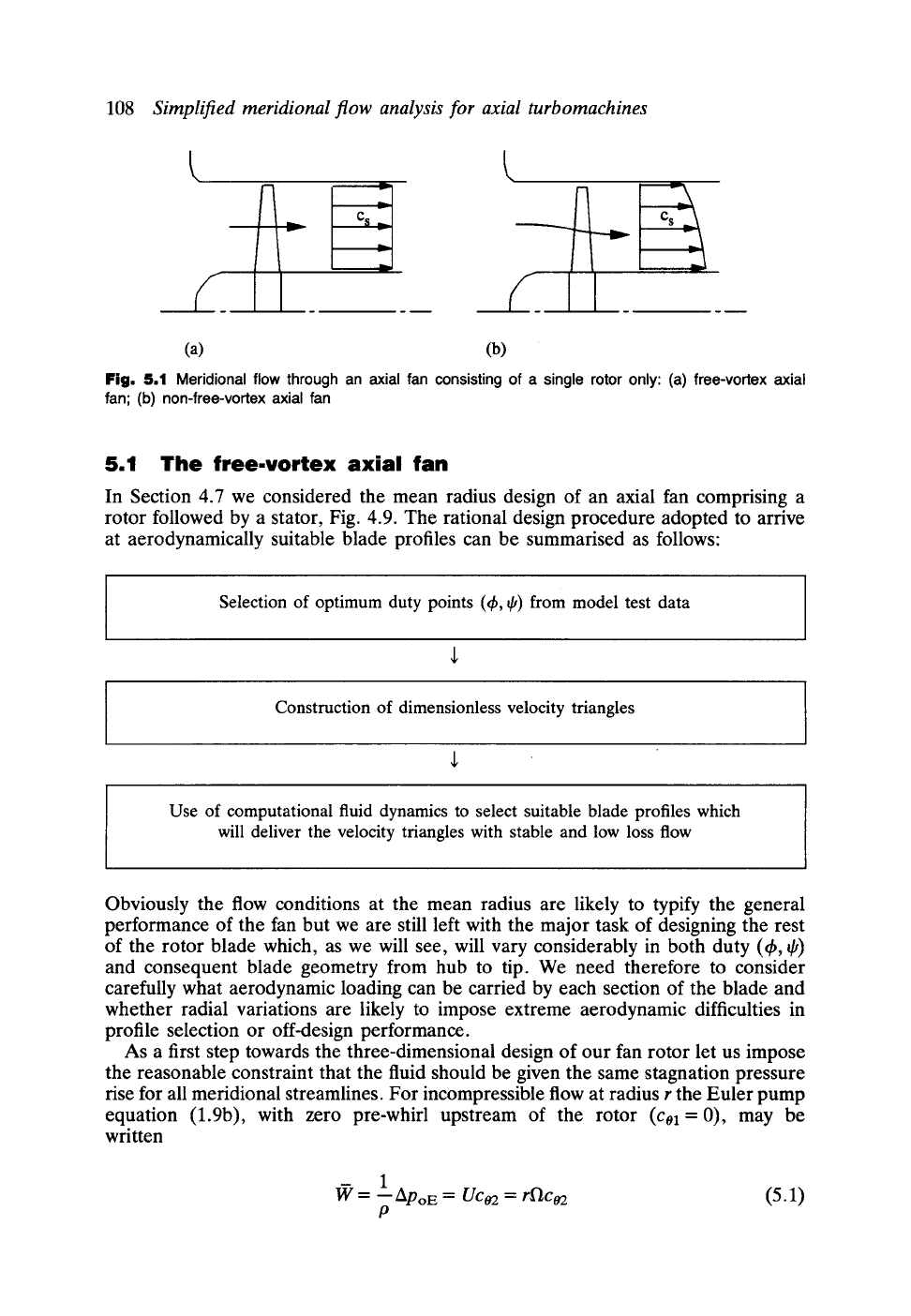
Now so far for axial machines we have assumed that the meridional velocity Cs is
constant for all meridional streamlines as illustrated for an axial fan in Fig. 5.1(a).
Downstream of the rotor, however, the flow may be swirling quite considerably,
resulting in an inward radial pressure gradient. This may well result in some radial
shifts in the meridional streamlines as illustrated in Fig. 5.1(b). As a result of this
the meridional velocity Cs will vary from hub to tip with consequent modification of
the velocity triangles which must be taken into account before the blade profiles are
designed.
Meridional flow analyses to handle this design problem are extremely complex.
In this chapter we will content ourselves with only the simplest techniques known
as radial equilibrium analysis, Sections 5.2 and 5.3, and actuator disc theory, Sections
5.4 and 5.5. Finally in Section 5.6 these analyses will be extended to deal with the
design of a complete axial fan or compressor comprising several blade rows and
including the meridional interference between them. Before turning to these,
however, we will begin in Section 5.1 by considering the special case of flee-vortex
design, the simplest and most popular method for three-dimensional design of axial
turbomachines.
108
Simplified meridional flow analysis for axial turbomachines
y_ll-
(a) (b)
Fig. 5.1 Meridional flow through an axial fan consisting of a single rotor only: (a) free-vortex axial
fan; (b) non-free-vortex axial fan
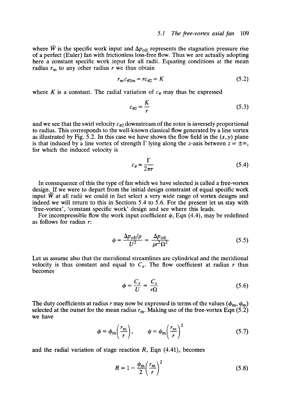
5.1 The free.vortex axial fan
In Section 4.7 we considered the mean radius design of an axial fan comprising a
rotor followed by a stator, Fig. 4.9. The rational design procedure adopted to arrive
at aerodynamically suitable blade profiles can be summarised as follows:
Selection of optimum duty points (~b, ~,) from model test data
Construction of dimensionless velocity triangles
Use of computational fluid dynamics to select suitable blade profiles which
will deliver the velocity triangles with stable and low loss flow
Obviously the flow conditions at the mean radius are likely to typify the general
performance of the fan but we are still left with the major task of designing the rest
of the rotor blade which, as we will see, will vary considerably in both duty (t h, ~,)
and consequent blade geometry from hub to tip. We need therefore to consider
carefully what aerodynamic loading can be carried by each section of the blade and
whether radial variations are likely to impose extreme aerodynamic difficulties in
profile selection or off-design performance.
As a first step towards the three-dimensional design of our fan rotor let us impose
the reasonable constraint that the fluid should be given the same stagnation pressure
rise for all meridional streamlines. For incompressible flow at radius r the Euler pump
equation (1.9b), with zero pre-whirl upstream of the rotor
(Col
=0), may be
written
l~ = _1 ApoE =
Uca2 = rl'lca2
(5.1)
P
5.1 The free-vortex axial fan 109
m
where W is the specific work input and
ADo E
represents the stagnation pressure rise
of a perfect (Euler) fan with frictionless loss-free flow. Thus we are actually adopting
here a constant specific work input for all radii. Equating conditions at the mean
radius rm to any other radius r we thus obtain
rmCo2m =
rco2 = K (5.2)
where K is a constant. The radial variation of co may thus be expressed
K
C0 2 -- __
r
(5.3)
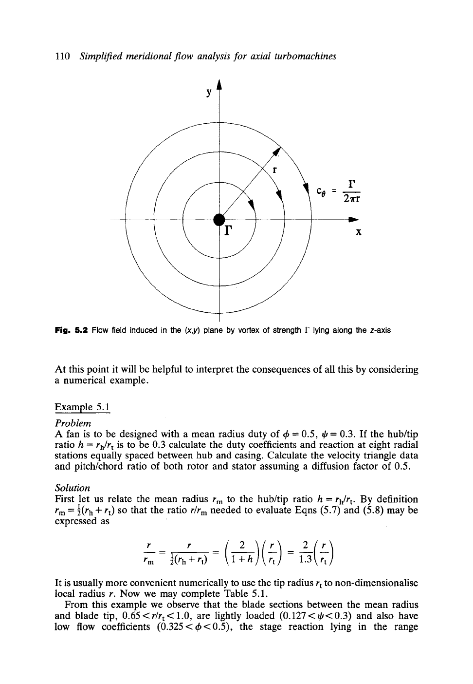
and we see that the swirl velocity c02 downstream of the rotor is inversely proportional
to radius. This corresponds to the well-known classical flow generated by a line vortex
as illustrated by Fig. 5.2. In this case we have shown the flow field in the (x, y) plane
is that induced by a line vortex of strength F lying along the z-axis between z = +~,
for which the induced velocity is
F
Co = 27rr (5.4)
In consequence of this the type of fan which we have selected is called a flee-vortex
design_If we were to depart from the initial design constraint of equal specific work
input W at all radii we could in fact select a very wide range of vortex designs and
indeed we will return to this in Sections 5.4 to 5.6. For the present let us stay with
'free-vortex', 'constant specific work' design and see where this leads.
For incompressible flow the work input coefficient ~, Eqn (4.4), may be redefined
as follows for radius r:
APoE/P ApoE
~,= U2 - pr2f~2 (5.5)
Let us assume also that the meridional streamlines are cylindrical and the meridional
velocity is thus constant and equal to Cx. The flow coefficient at radius r thus
becomes
Cx Cx
~b- U - rf~ (5.6)
The duty coefficients at radius r may now be expressed in terms of the values (thm, ~m)
selected at the outset for the mean radius rm. Making use of the free-vortex Eqn (5.2)
we have
6 = 6m , ~t= ~'m
(5.7)
and the radial variation of stage reaction R, Eqn (4.41), becomes
R = 1- (5.8)
110
Simplified meridional flow analysis for axial turbomachines
\
/
I'
Co = 2rr
x
Fig. 5.2 Flow field induced in the
(x,y)
plane by vortex of strength
F
lying along the z-axis
At this point it will be helpful to interpret the consequences of all this by considering
a numerical example.
Example 5.1
Problem
A fan is to be designed with a mean radius duty of ~b = 0.5, ~ = 0.3. If the hub/tip
ratio h =
rh/r t
is to be 0.3 calculate the duty coefficients and reaction at eight radial
stations equally spaced between hub and casing. Calculate the velocity triangle data
and pitch/chord ratio of both rotor and stator assuming a diffusion factor of 0.5.
Solution
First let us relate the mean radius r m to the hub/tip ratio h =
rh[r t.
By definition
r m = 89 h + rt) so that the ratio
r/r m
needed to evaluate Eqns (5.7) and (5.8) may be
expressed as
r _ r (2)(~t) 1.-~(r~)
rm l(r h -I- rt) 1 + h
It is usually more convenient numerically to use the tip radius r t to non-dimensionalise
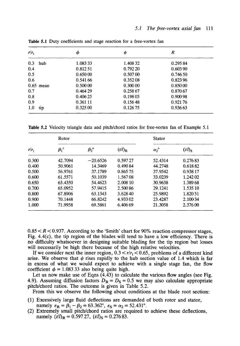
local radius r. Now we may complete Table 5.1.
From this example we observe that the blade sections between the mean radius
and blade tip,
0.65<r/rt<l.O,
are lightly loaded (0.127<~<0.3) and also have
low flow coefficients (0.325<th<0.5), the stage reaction lying in the range
5.1 The free-vortex axial fan 111
Table 5.1 Duty coefficients and stage reaction for a free-vortex fan
r/r t dp ~ R
0.3 hub 1.083 33 1.408 32 0.295 84
0.4 0.812 51 0.792 20 0.603 90
0.5 0.650 00 0.507 00 0.746 50
0.6 0.541 66 0.352 08 0.823 96
0.65 mean 0.500 00 0.300 00 0.850 00
0.7 0.464 29 0.258 67 0.870 67
0.8 0.406 25 0.198 05 0.900 98
0.9 0.361 11 0.15648 0.921 76
1.0 tip 0.325 00 0.12675 0.93663
Table 5.2 Velocity triangle data and pitch/chord ratios for free-vortex fan of Example 5.1
Rotor Stator
r/r t
fll ~ f12 ~
(t/l)R
~2 ~ (t//)S
0.300 42.7094 -20.6526 0.597 27 52.4314 0.276 83
0.400 50.9061 14.3469 0.490 84 44.2748 0.618 82
0.500 56.9761 37.1789 0.865 75 37.9542 0.938 17
0.600 61.5571 50.1039 1.567 08 33.0239 1.242 02
0.650 63.4350 54.4623 2.008 10 30.9638 1.389 68
0.700 65.0952 57.9415 2.500 86 29.1241 1.535 10
0.800 67.8906 63.1343 3.628 40 25.9892 1.820 51
0.900 70.1448 66.8242 4.933 02 23.4287 2.10(}34
1.000 71.9958 69.5861 6.406 69 21.3058 2.376 00
0.85 < R < 0.937. According to the 'Smith' chart for 90% reaction compressor stages,
Fig. 4.4(c), the tip region of the blades will tend to have a low efficiency. There is
no difficulty whatsoever in designing suitable blading for the tip region but losses
will necessarily be high there because of the high relative velocities.
If we consider next the inner region, 0.3 <
r/r t
< 0.65, problems of a different kind
arise. We observe that ~ rises rapidly to the hub section value of 1.4 which is far
in excess of what we would expect to achieve with a single stage fan, the flow
coefficient ~b = 1.083 33 also being quite high.
Let us now make use of Eqns (4.43) to calculate the various flow angles (see Fig.
4.9). Assuming diffusion factors DR = Ds = 0.5 we may also calculate appropriate
pitch/chord ratios. The outcome is given in Table 5.2.
From this we observe the following about conditions at the blade root section"
(1) Excessively large fluid deflections are demanded of both rotor and stator,
namely eR
= ~1 - f12 =
63.362~ es = a2 = 52.431 ~
(2) Extremely small pitch/chord ratios are required to achieve these deflections,
namely (t/0R = 0.597 27, (t//)S = 0.276 83.
112 Simplified meridional flow analysis for axial turbomachines
Although in theory we could design cascades to achieve these deflections, albeit
with poor aerodynamic performance, the blades would exhibit such enormous taper
that we would be hard placed to accommodate the root section of the blade, the
chord of which would be over seven times greater than the chord at the mean
radius r m.
One possible solution to the dilemma posed in Example 5.1 would be to select
a higher hub/tip ratio. Thus from Tables 5.1 and 5.2 we see that quite acceptable
(~b, ~,) duties and velocity triangles are obtained for
r/r t
>
0.5 which indicates a suitable
value for h. A second solution might be to adopt a less demanding (thm, ~'m) duty
at the mean radius. The reader can make use of the simple Pascal program FVFAN,
the source code of which is provided on the accompanying PC disc, to experiment
with this. The most appropriate solution in practice, in order to maintain low values
of hub/tip ratio and thus the maximum available annulus flow area, is to abandon
our initial aim of designing for constant specific work W input at all radii. Instead
we may progressively reduce W as we move radially inward from r m
to
rh and thereby
reduce the pressure rise coefficient ~, to acceptable values, less than say 0.4. This
will help to maintain much lighter aerodynamic loading in the blade root region but
also pitch/chord ratios in excess of 1.0 and hence a wider stall-free range (see Section
4.8). Unfortunately this approach would entail a departure from free-vortex flow,
resulting in a non-uniform meridional velocity profile, Fig. 5.1(b). Complex
calculations are required to evaluate the variation of Cs with radius and two of the
most simple analyses will now be presented in Sections 5.2 to 5.5.
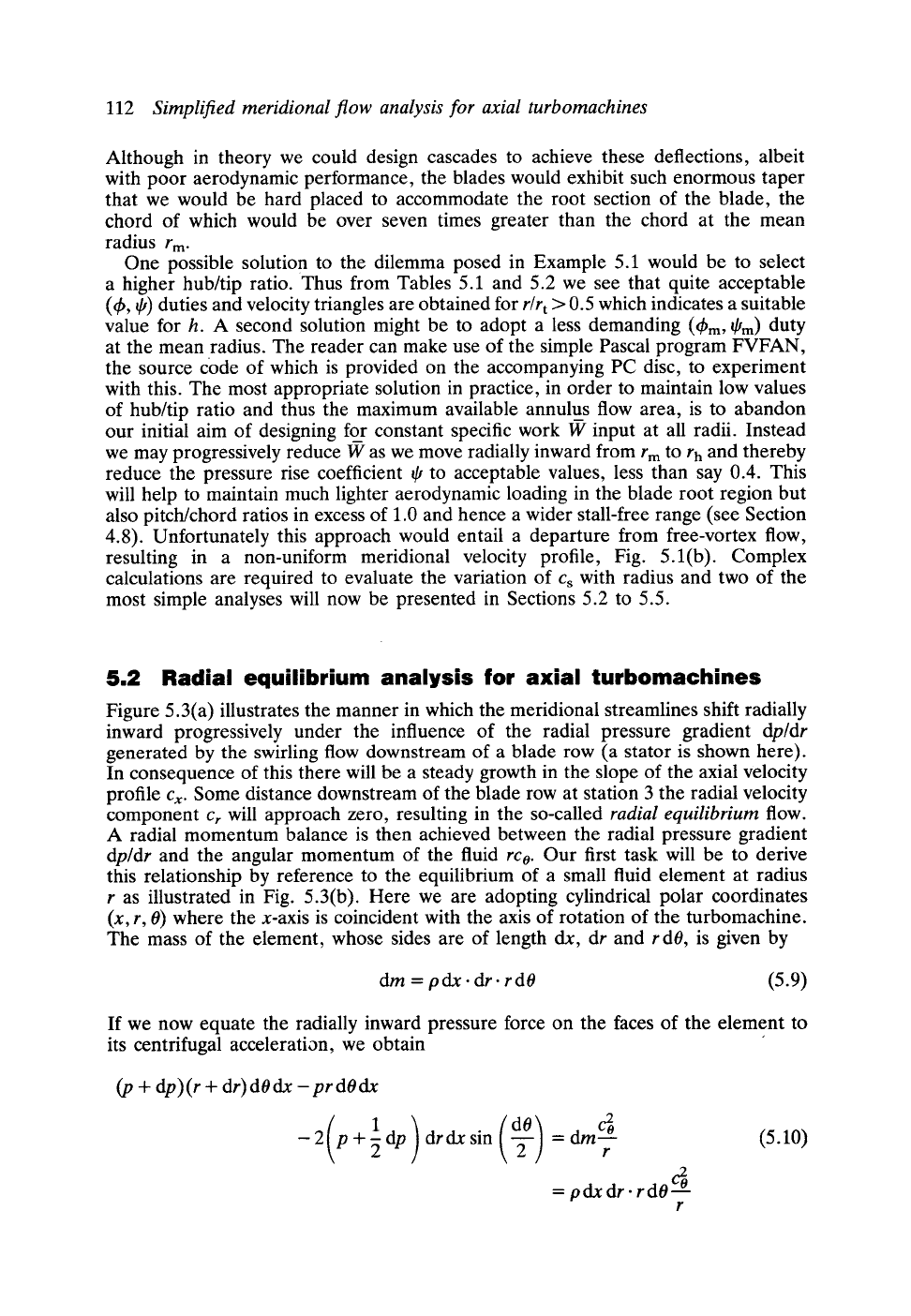
5.2 Radial equilibrium analysis for axial turbomachines
Figure 5.3(a) illustrates the manner in which the meridional streamlines shift radially
inward progressively under the influence of the radial pressure gradient dp/dr
generated by the swirling flow downstream of a blade row (a stator is shown here).
In consequence of this there will be a steady growth in the slope of the axial velocity
profile Cx. Some distance downstream of the blade row at station 3 the radial velocity
component Cr will approach zero, resulting in the so-called radial equilibrium flow.
A radial momentum balance is then achieved between the radial pressure gradient
dp/dr and the angular momentum of the fluid rco. Our first task will be to derive
this relationship by reference to the equilibrium of a small fluid element at radius
r as illustrated in Fig. 5.3(b). Here we are adopting cylindrical polar coordinates
(x, r, 0) where the x-axis is coincident with the axis of rotation of the turbomachine.
The mass of the element, whose sides are of length dx, dr and r dO, is given by
dm = pdx. dr- r dO (5.9)
If we now equate the radially inward pressure force on the faces of the element to
its centrifugal acceleration, we obtain
(p + dp)(r + dr)dOdx-prdOdx
( 1
-2
p+gdp
) 2
drdx sin ~ = dm c'b (5.10)
r
= pdx dr. rdO c2~
r
5.2
Radial equilibrium analysis for axial turbomachines
113
p+dp
;I
.y
p-~-ap/z..~4~ ~ ar ~+dp/2
r~ IP
-/
/
/
/
f
~ dx
J
(a) (b)
Fig. 5.3 Radial equilibrium of a small fluid element downstream of a turbomachine blade row: (a)
meridional streamline shift and axial velocity profile development; (b) pressure forces on a small fluid
element at station 3
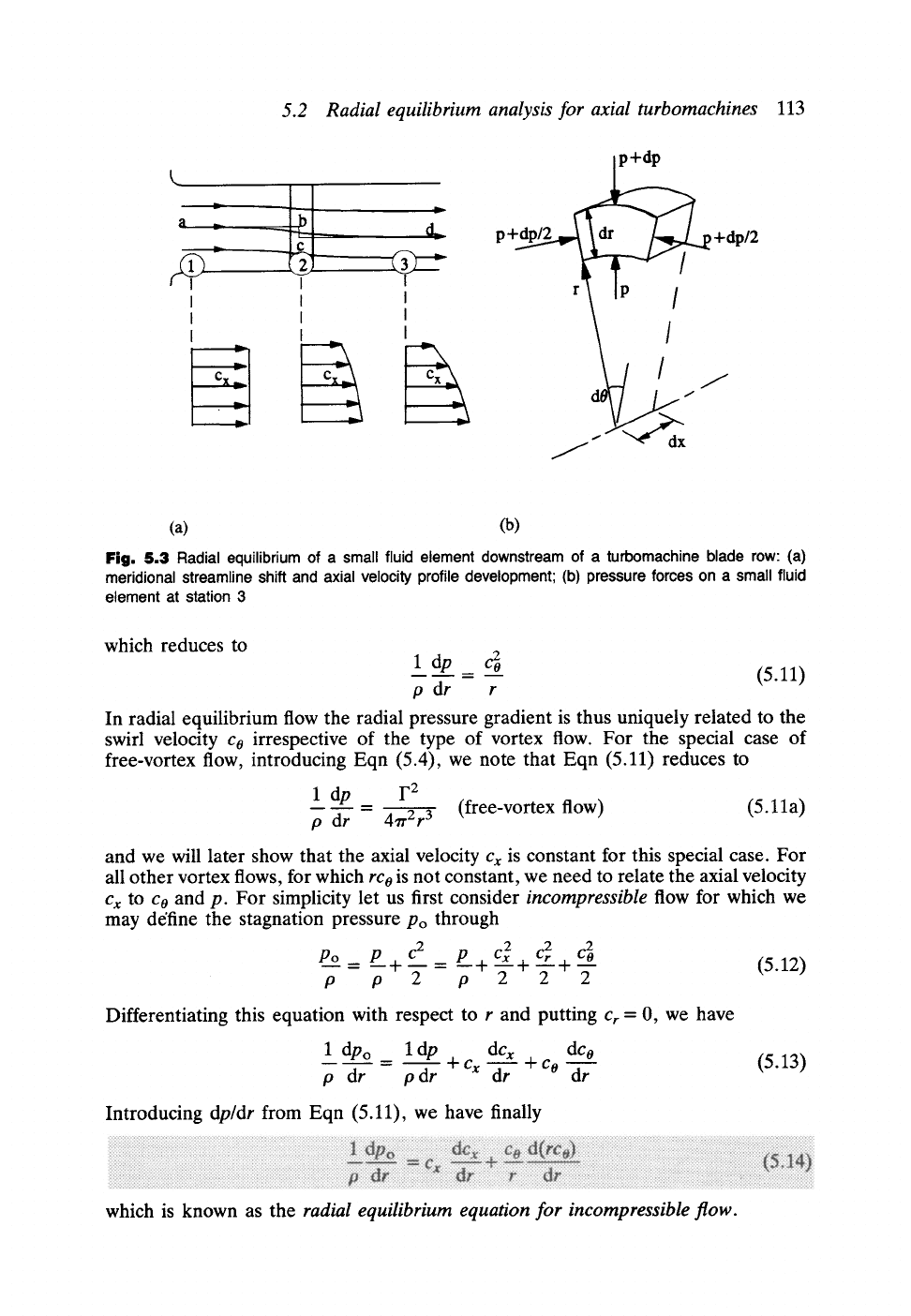
which reduces to
ldp cEo
= -- (5.11)
p dr r
In radial equilibrium flow the radial pressure gradient is thus uniquely related to the
swirl velocity
co
irrespective of the type of vortex flow. For the special case of
free-vortex flow, introducing Eqn (5.4), we note that Eqn (5.11) reduces to
1 dp F 2
= (free-vortex flow) (5.11a)
p dr 47r 2r 3
and we will later show that the axial velocity
Cx
is constant for this special case. For
all other vortex flows, for which
rco
is not constant, we need to relate the axial velocity
Cx
to
Co
and p. For simplicity let us first consider
incompressible
flow for which we
may de'fine the stagnation pressure Po through
P-2~ P c2 P--+c2 c2 c2~ (5 12)
o-7 +T= o T +T+T
Differentiating this equation with respect to r and putting
Cr
= 0, we have
_ dcx dco
1 dpo l dp
+cx +Co
p dr - p dr -~r dr
Introducing
dp/dr
from Eqn (5.11), we have finally
(5.13)
which is known as the
radial equilibrium equation for incompressible flow.