Lallart M. Ferroelectrics: Characterization and Modeling
Подождите немного. Документ загружается.

Ferroelectrics Study at Microwaves
209
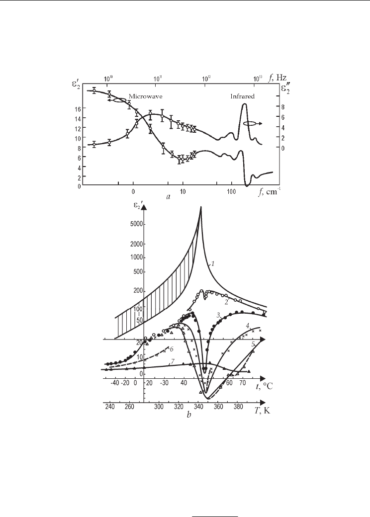
Figure 6 shows main results of microwave study of TGS (another well known order-
disorder type ferroelectric). Dipole relaxation in the polar phase demonstrates ε′
2
(
f
)
decrease between 10 and 300 GHz with ε″
2
(
f
) maximum near 100 GHz, Fig. 6, a. Note, that
1 cm
−
1
corresponds to f = 30 GHz.
Fig. 6. TGS crystals microwave study: ε'
2
and ε
″
2
frequency dependence at 300 K (a);
ε'
2
temperature dependence at frequencies: 1 – 1 KHz, 2 – GHz, 3 – 16 GHz, 4 – 26 GHz,
5 – 37 GHz , 6 – 80 GHz, 7– 250 GHz (b)
In contrast to Rochelle Salt, TGS is not piezoelectric in the paraelectric phase. In the Curie
point ε′
2
(T) at microwaves demonstrates minimum. The family of ε*
2
(
f
,T) characteristics
can be well described by the modified Debye equation
()
*
ІR
0
,
C
T
Ti
εω ε
θωτ
=+
−+
(5)
Ferroelectrics - Characterization and Modeling
210
where ε
ІR
is the infrared input to permittivity. In a paraelectric phase TGS crystal microwave
properties can be described by the parameters C = 3200 K, θ = 321 К and τ
0
= 2⋅10
–10
sec/К.
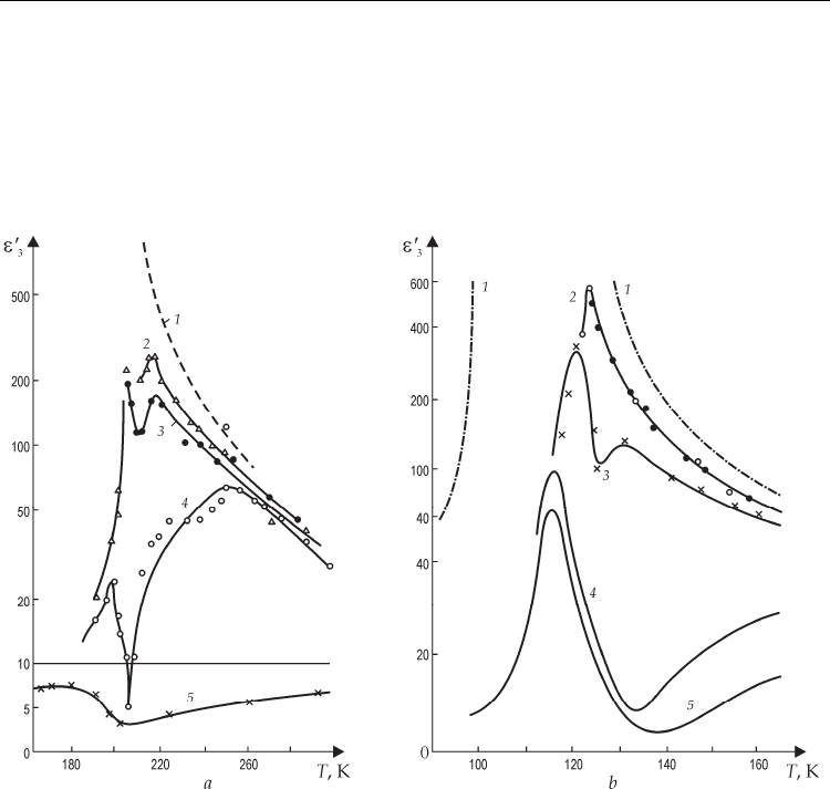
Microwave properties of the DKDP ε*
3
( f ,T) dependences that is characterized by the heavy
deuteron relaxation looks very similar to TGS and Rochelle Salt crystals, Fig. 7, a. However,
in the KDP crystals protons dynamics makes dielectric dispersion spectra similar to displace
ferroelectric, Fig. 7, b.
Fig. 7. Microwave dielectric dispersion in ferroelectrics of KDP type: KD
2
PО
4
ε′
3
(T) at
frequencies: 1 – 0.3 GHz; 2 – 8.6 GHz ; 3 – 9.7 GHz ; 4 – 26 GHz; 5 – 250 GHz (a);
КН
2
РО
4
ε′
3
(T) at frequencies: 1 – 1 kHz, 2 –9.4 GHz; 3 – 80 GHz , 4 –200 GHz; 5 –340 GHz (b)
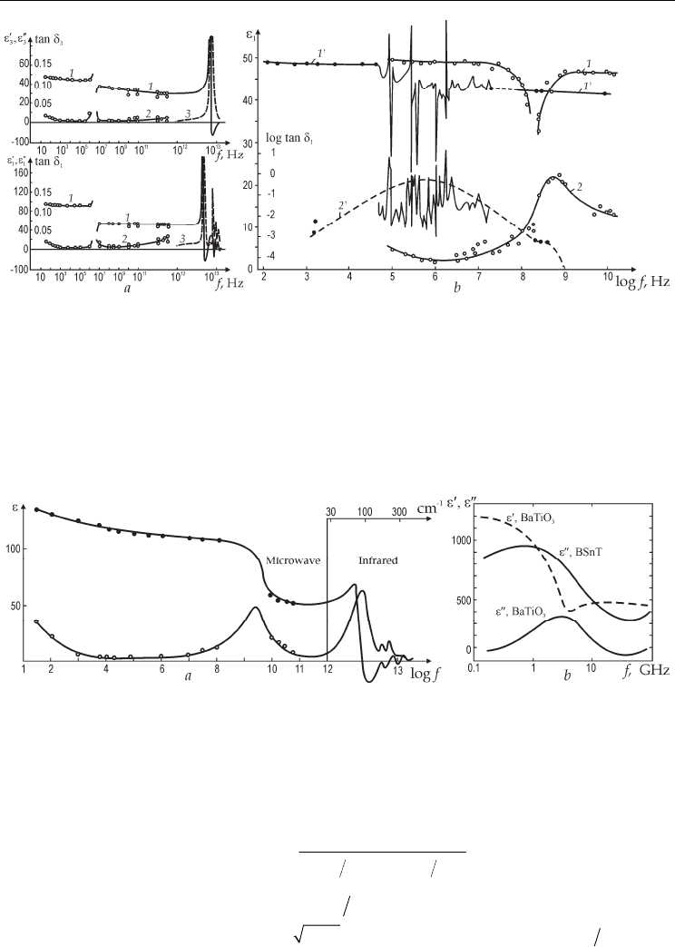
2.5 Ferroelectrics of displace type at microwaves
In the ferroelectric phase the ε-dispersion at microwaves depends on domain walls
vibration. That is why in the single-domain crystal practically no decrease in ε at
microwaves is observed, as it is shown in Fig. 8, a with the example of LiNbO
3
crystal.
Resonant change in ε
3
and ε
1
at megahertz frequencies means only piezoelectric resonances
while far infrared ε-maxima are obliged to the lattice vibrations.
However, in the multidomain crystals dielectric dispersion at microwaves results in ε-
decrease that is accompanied by tanδ maximum near frequency 9 GHz, shown in Fig. 8, b for
multidomain LiTaO
3
crystal (there are also many piezoelectric resonances in the megahertz
area).
Ferroelectrics Study at Microwaves
211
Fig. 8. Dielectric spectrums of ferroelectric crystals at 300 K: single domain LiNbO
3
ε
3
and
tanδ
3
, ε
1
and tanδ
1
(a); LiTaO
3
: 1 - ε
1
, 2 – tanδ
1
single domain; 1 – ε
1
, 2 – tanδ
1
for multidomain
crystal (b)
Polycrystalline ferroelectrics have obviously multidomain structure and, as a result, show
microwave ε-dispersion, as it is shown in Fig. 9 for PbTiO
3
and BaTiO
3
(ε″ maximum is
observed near frequency of 9 GHz while ε′ decreases in two times). More “soft” ceramics
Ba(Ti,Sn)O
3
demonstrate microwave dispersion at lower but microwave frequencies: broad
ε″ maximum is seen at 1 GHz.
Fig. 9. Ferroelectric permittivity frequency dependence at 300 K: PbTiO
3
ceramics
1 - ε′ and 2 - ε″ (a); ceramics BaTiO
3
and Ba(Ti,Sn)O
3
= BSnТ microwave study (b)
Microwave properties of displace type ferroelectrics in the paraelectric phase depends on
soft lattice vibration mode. That is why Lorentz oscillator model
is a basic model to describe
ε* frequency dependence:
()
() ( )
()
2
0
*
1
TO TO
i
εε
εω ε
ωω ωω
∞
−∞
=+
++Γ
. (6)
In this equation let assume
() ( ) ( )
0 CT
εε θ
−∞= − and soft mode critical frequency
dependence on temperature is
TO
AT
ωθ
=−. Relative damping factor is
TO
γ
ω
Γ= , as a
result:
Ferroelectrics - Characterization and Modeling
212
()
()
()
22
2
2
2222
,
AT
TCA
AT
θω
εω ε
θω γω
∞
−−
′
−=
−− +
;
()
()
2
2
2222
,TCA
AT
γω
εω ε
θω
γ
ω
∞
′′
−=
−− +
; (7)
()
2
tg
AT
γω
δ
θ
≈
−
,
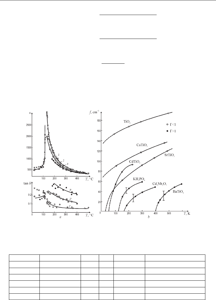
where A is Cochran coefficient, C is Сurie-Weiss constant, γ is damping coefficient. From ε
and tanδ temperature dependences at various frequencies, as for instance Fig. 10, a, soft
mode temperature dependence can be calculated, Fig. 10, b. Main lattice dynamics
parameters of studied ferroelectrics are shown in Table 2.
Fig.10. Paraelectrics at microwaves: BaTiO
3
ε (1, 2, 3) and
tanδ (1
′
, 2
′
, 3
′
) temperature
dependence at different frequencies: 1 – 9.4–37 GHz; 2 – 46 GHz; 3 – 76 GHz (a); soft modes
frequency dependence for various paraelectrics obtained by microwave and far infrared
experiments (b)
Material
Р
с
,
μ
Q/cm
2
Т
к
,
К
θ,
К
C
⋅10
−
4
,
К
А
/
2π,GHz⋅ К
−
1
/
2
CaTiO
3
– – – 90 4.5 170
SrTiO
3
– – 35 8.4 180
BaTiO
3
30 400 388 12 75
PbTiO
3
80 780 730 15 90
KNbO
3
30 685 625 18 95
LiNbO
3
70 1500 – – –
Table 2. Lattice parameters of some ferroelectric materials
Ferroelectrics Study at Microwaves
213
3. Ferroelectric films investigation
3.1 Various methods comparison
Most of existing studies of ferroelectric films (22 published experiments listed in the review
by Gevorgian & Kollberg, 2001) are drawn with the use of electrodes. For instance, the
opposite-electrodes method is employed to study the system Pt/BST/Pt (Banieki et al.,
1998). However, in most cases, ferroelectric film is studied between planar electrodes
applied to the opened surface of the film. In that case, film parameters can be extracted from
the impedance of interdigital planar capacitor as well as from the coplanar phase shifter
study. Nevertheless, in all mentioned methods, the “natural film” microwave ε and tanδ
remain unknown, because a complex system of “electrode-film-electrode” is investigated.
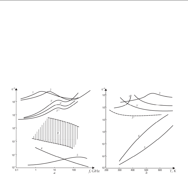
Nevertheless, the data related to the “natural film” as well as to film components properties
and substrates properties are important: their frequency and temperature characteristics are
shown in Fig. 11.
Fig. 11. Films, ceramics and crystals characterization at microwaves; ε
″
frequency
dependence at 300 K: 1 – BaTiO
3
ceramics; 2 – PbTi,ZrO
3
ceramics; 3
′
– BST (Ba,SrTiO
3
)
ceramics; 3
″
– BST film 15 μm, 3″′ – BST film 2 μm, 4 – Si crystal, 5 – GaAs crystal; 6 – mixed
oxides of BaO, TiO
2
, PbO, SrO before film synthesis (a); ε
″
temperature dependence at 80
GHz: 1 – BaTiO
3
ceramics; 2 –PbTi,ZrO
3
ceramics, 3
′
– BST ceramics, 3
″
– BST film 15 μm, 4 –
Si crystal, 5 – GaAs crystal (b)
It is necessary to note that dielectric constant calculation from the planar capacitance is
approximate while microwave loss cannot be even estimated. Point is that metallic
electrodes strongly affect onto measured ε
film
value (and especially onto film’s tanδ) through
the mechanical stress and skin effect in electrodes. Moreover, as a rule, dielectric parameters
of film with interdigital electrodes are usually obtained at low frequency (of about 1 MHz);
however, next this information is applied to microwave device elaboration. In the mass
production small portion of the substrate could be sacrificed for test electrodes area.
However, in laboratory study, single film gets unusable after electrodes deposition. So the
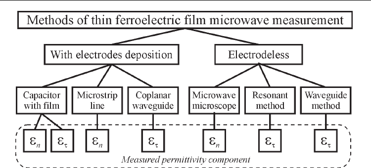
electrodeless techniques are very important. A comparison of different methods of
ferroelectric film study at microwaves is shown in Fig. 12.
Ferroelectrics - Characterization and Modeling
214
Fig. 12. Microwave methods for ferroelectric films study
Thin ferroelectric film is usually deposited onto dielectric substrate. Practically used films
have thickness of 0.1–1 mm. Thermal expansion coefficient and lattice parameter of the
substrate are different from those of thin film. Thus, film suffers from mechanical stress.
This stress changes films properties comparing to the properties of bulk ferroelectric.
Dielectric constant and loss could be decreased by order of magnitude. On the other hand,
directional mechanical stress contributes to the anisotropy of film’s parameters. So methods
of films study must not only register film’s response, but consider anisotropy as well.
Because of high dielectric constant and loss microwave testing of ferroelectrics is quite
complex. In thin film study a question becomes even more complicated by film small
thickness. This work presents waveguide method, suitable for thin films study.
3.2 Waveguide method description
Common technique for dielectric material measuring in the waveguide usually relies on
complex scattering parameters measurement of waveguide section which cross section is
filled with studied material. That technique can be easily adapted for measurement of the
layered structures where properties of one layer are unknown.
However, this approach faces irresolvable difficulties with thin films. Simple estimation
shows that X-band waveguide being entirely baffled with film of 1 μm thickness that has
ε = 1000 and tanδ = 0.05 has phase perturbation of only about 0.4°, and brings attenuation of
about -0.002 dB. These quantities are obviously out of equipment resolution capabilities.
That is why, the goal is to arrange the interaction of film with electromagnetic field in such a
way that brings recognizable response.
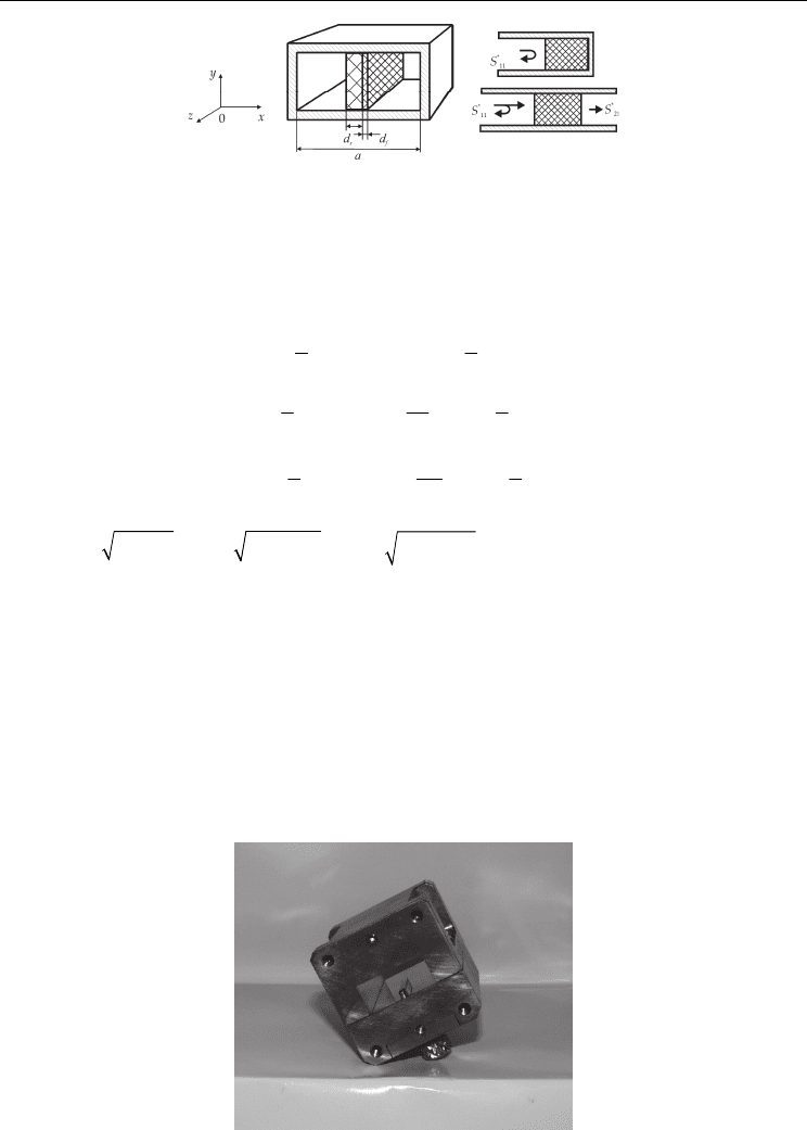
In proposed method, film-on-substrate specimen is centrally situated along the waveguide
(Fig. 13). It is known that electric field intensity is highest in centre of waveguide so highest
possible interaction of film with the electric field is provided.
Dielectric constant and loss can be found by solving scattering equations at one certain
frequency. However, the accuracy of one-point technique is strongly affected by the accidental
error (Baker-Jarvis, 1990). Proposed method accuracy is improved by the recording of
complete frequency dependence of scattering parameters using contemporary vector network
analyzer. Similarly to the method for bulk samples study, gathered experimental data then
processed utilizing nonlinear least squares curve fitting technique (3).
Ferroelectrics Study at Microwaves
215
Fig. 13. Schematic representation of experiment
For the S-parameters calculations, electromagnetic field problem can be solved utilizing
longitudinal wave representation (Egorov, 1967), (Balanis, 1989). Applying boundary
conditions on media boundaries yields a complex nonlinear equation with respect to
complex propagation constant:
tan tan ;
22
atan cot ;
22
atan cot ,
22
sssf ff
ss s s
s
ff f f
f
aa
aa
dd
aa
dd
ββϕβ βϕ
β
ϕβ β
β
β
ϕβ β
β
−= −
=−+ −
=++ +
(8)
where
22
k
βγ
=−,
22
ss
k
β
εγ
=−,
22
ff
k
β
ε
γ
=−
are transverse wave numbers in the
air, substrate and film media respectively,
d
s
is substrate thickness, d
f
is film thickness, a is
width of wide wall of waveguide,
γ is propagation constant, k is free space wave number. In
this equation, the position of film-substrate boundary assumed to be exactly at the middle of
waveguide, however known displacement can be taken in account.
3.3 Experimental result
Described measurement technique was utilized for study of BST thin films. The film of
about 1
μm thickness was deposited onto 0.5mm MgO substrate in a pulsed laser ablation
setup. Special measurement cell was elaborated to provide reliable contact of specimen
under test with waveguide walls, Fig. 14. Automatic network analyzer was calibrated with
Fig. 14. Waveguide measurement cell for thin films study
Ferroelectrics - Characterization and Modeling
216
appropriate X-band calibration kit. Then two reference measurements were performed. First
one is a measurement of empty cell. It makes possible to determine cell’s electrical length
more precisely. Second one is the measuring of substrate alone. This stage is required to
determine the actual loss of the “substrate-in-waveguide” system because only on this
background film properties will be recognized.
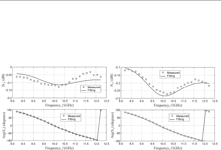
Numerous experiments with the same samples show reliable repeatability of experiments.
Fig. 15 illustrates an example of measured data fitting for MgO substrate and 0.84
μm thick
BST film.
Fig. 15. Measured data and calculation for: 0.5 mm thickness MgO substrate (
a), 0.84 μm BST
film on 0.5 mm thickness MgO substrate. Specimen dimensions are 22
× 10 mm (b)
Average value of substrate permittivity is
ε′ = 9.9, tanδ = 3⋅10
-4
. As to the film fitting to the
calculation exhibits good agreement and yields
ε = 450, tanδ = 0.05. Both reflection of
shorted waveguide with sample and transmission in the 2-port system can be used,
however the first method is preferable because of higher sensitivity.
Presented technique of thin ferroelectric film examination can be applied also for study of
relatively thick (10
μm and more) films that have non-ferroelectric nature. The method can
be successfully used, for example, to study semiconductor films deposited onto dielectric
subtract when traditional metering technique brakes down.
3.4 Uncertainty of non-resonant waveguide method for thin films measurement
Ideal contact of studied specimen with waveguide walls is hard to achieve and there small
air gaps on the interface. These gaps may degrade accuracy substantially. Though some
estimations consider 2.5-7
μm gap acceptable (Champlin & Glover, 1966), this value is too
general and hard to verify. So it is desirable to enforce interface contact as much as possible.
Though films permittivity and loss are estimated using least squares curve fitting technique
(3), let’s begin uncertainty estimation with single point accuracy. Parameters of studied film
are derived from indirect measurements. They contain uncertainties of dimensions
measurements, scattering parameters magnitude and phase uncertainties, and rounding
errors of processing procedure. In waveguide experiment magnitude and phase of reflection
coefficient are measured directly (real and imaginary part to be precise, but that does not
change further explanations). Their simulation values depend on sample’s physical
dimensions, permittivity and loss:
Ferroelectrics Study at Microwaves
217
()
,tan , ,tan , , ,
ff
ss
f
s
SS Ldd
εδεδ
=
, (9)
where
,tan
ff
εδ
is permittivity and loss of studied film, ,tan
ss
εδ
is permittivity and loss of
the substrate, L
is sample’s length, ,
f
s
dd is film and substrate thickness respectively. This
equation is implicit function, which relates mentioned parameters.
Due to low loss substrate effective loss of measurement cell is low. In such conditions
permittivity is mainly found by phase measurement, whereas loss is found from magnitude
measurements (Janezic & Jargon, 1999). Large difference in sensitivities allows separate
analysis of permittivity and loss uncertainties.
Sensitivities of calculated values of film’s permittivity and loss to uncertainties of directly
measured values can be estimated using rules of implicit function differentiation. Then for
every given frequency permittivity and loss uncertainty can be expressed as:
()
()
2
2
2
2
11 11 11
11
11
2
22
2
11 11 11
11
11
1
;
1
tan tan ,
tan
tan
ffs
fs
f
ffs
fs
f
SS S
LdS
S
Ld
SS S
LdS
S
Ld
εε
ε
ε
δδ
δ
δ
∂∠ ∂∠ ∂∠
Δ= Δ + Δ +Δ∠ + Δ
∂∠
∂∂ ∂
∂
∂∂ ∂
Δ= Δ+ Δ+Δ+ Δ
∂
∂∂ ∂
∂
(10)
where
LΔ
uncertainty of length measurement,
f
dΔ is uncertainty of film thickness
measurement,
11
SΔ is uncertainty of magnitude of scattering parameter, SΔ∠ is
uncertainty of phase of scattering parameter,
s
ε
Δ and tan
s
δ
Δ is uncertainty of substrate’s
parameters. Listed uncertainties are related to instrument uncertainties. Uncertainty of
substrate thickness measurement is usually much smaller, than listed values, so it is omitted
for the sake of clarity, though might be accounted exactly same way. Listed uncertainties
were estimated numerically for the following conditions: frequency 10 GHz, film’s thickness
1
μm, film’s permittivity ε = 500, loss tanδ = 0.05, sample length 20 mm, substrate thickness
0.5 mm, permittivity ε = 9.9, loss tanδ = 10
–4
, their values presented in Table 3. Table 4
presents summary on instrument uncertainties.
11
,de
g
f
S
ε
∂∠
∂
11
de
g
,
S
Lm
∂∠
∂
11
de
g
,
f
S
dm
∂∠
∂
11
,de
g
s
S
ε
∂∠
∂
0.04 35000
7
2.2 10⋅
22
11
,
S
dB
Lm
∂
∂
11
,
f
S
dB
dm
∂
∂
11
,
tan
s
S
dB
δ
∂
∂
11
,
tan
f
S
dB
δ
∂
∂
30 1700 0.02 4.23
Table 3. Sensitivities to uncertainties of directly measured values
Ferroelectrics - Characterization and Modeling
218
Parameter Value Note
ΔL
10 μm
Micrometre screw
Δd
f
10 nm Reflectometer
Δε
s
0.1 1%
Δtanδ
s
10
-4
10%
Δ|S
11
|
0.02 HP 8510C
Δ∠S
11
2°
HP 8510C
Table 4. Instrument uncertainties
For the film under consideration uncertainty of permittivity measurement Δε/ε is about
14%, while uncertainty of loss measurement
tan tan
f
δδ
Δ is about 93%. For the film with
loss tanδ = 0.1 loss uncertainty will be 47%.
If method applied for film study in production process, i.e. the same substrate used in all
measurements, then uncertainty of substrate permittivity and loss could be eliminated and
permittivity uncertainty improves to about 10%.
These values present worst case estimation of single point measurement. Uncertainty of
final parameters is reduced by least squares processing. With 50 point equally distributed
along measurement frequency range sensitivity to uncertainty of scattering parameter
determination can be reduced by order of magnitude to
11 11
tan
1
3 ; 0.15.
deg
ff
SS
εδ
∂∂
==
∂∠ ∂
Then averaged uncertainty of film’s permittivity reduces to 2% and loss to 10%.
3.5 Coplanar line method
In actual devices a system of electrodes is deposited on the surface of ferroelectric film.
Geometry of the electrodes depends on film permittivity. At the same time metal electrodes
can modify film permittivity and loss. Therefore it would be desirable to perform
measurement directly in the device with deposited electrodes.
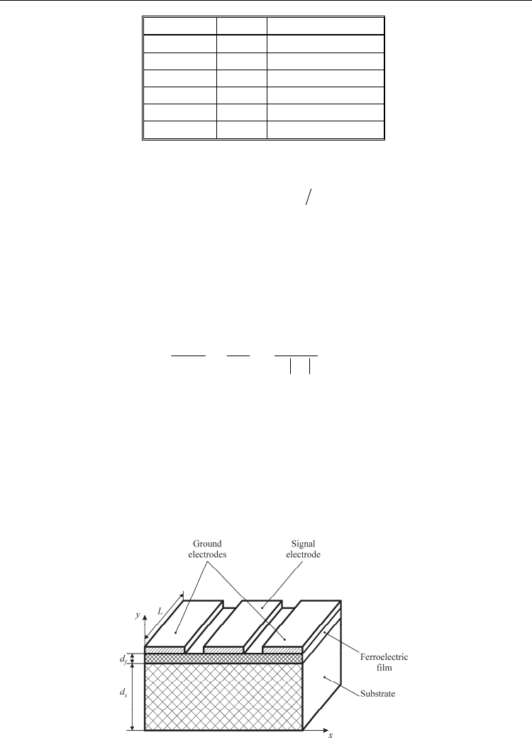
One of the most usable electrode system forms a coplanar line, Fig.16. Measurement of
permittivity and loss of ferroelectric film integrated in coplanar line is discussed below.
Fig. 16. Coplanar line on substrate with deposited ferroelectric film