Kothari D.P., Nagrath I.J. Modern Power Systems Analysis
Подождите немного. Документ загружается.

ffil
uodern
Power
Slrstem
Analvsis
PROB
iEii/iS
7.1 For
Example
7.1
calculate
the extra
cost
incurred
in
Rsftr,
if a load
of
220
MW is
scheduled
as
Pct=
Pcz
=
110
MW.
7.2 A
constant load
of 300
Mw
is supplied
by two
200
Mw
generators,
I
and
2,
for which
the respective
incremental
fuel costs
are
dcr
Po,
=o'lOPGl
+20'0
dcz
dPo,
-
o'lzPc2
+ 15'o
with powers
Pc in
MW and
costs
c
in
Rsar.
Determine
(a)
the
most
economical
division
of load
between
the
generators,
and
(b)
the
saving in
Rs/day
thereby
obtained
compared
to equal
load
sharing
between
machines.
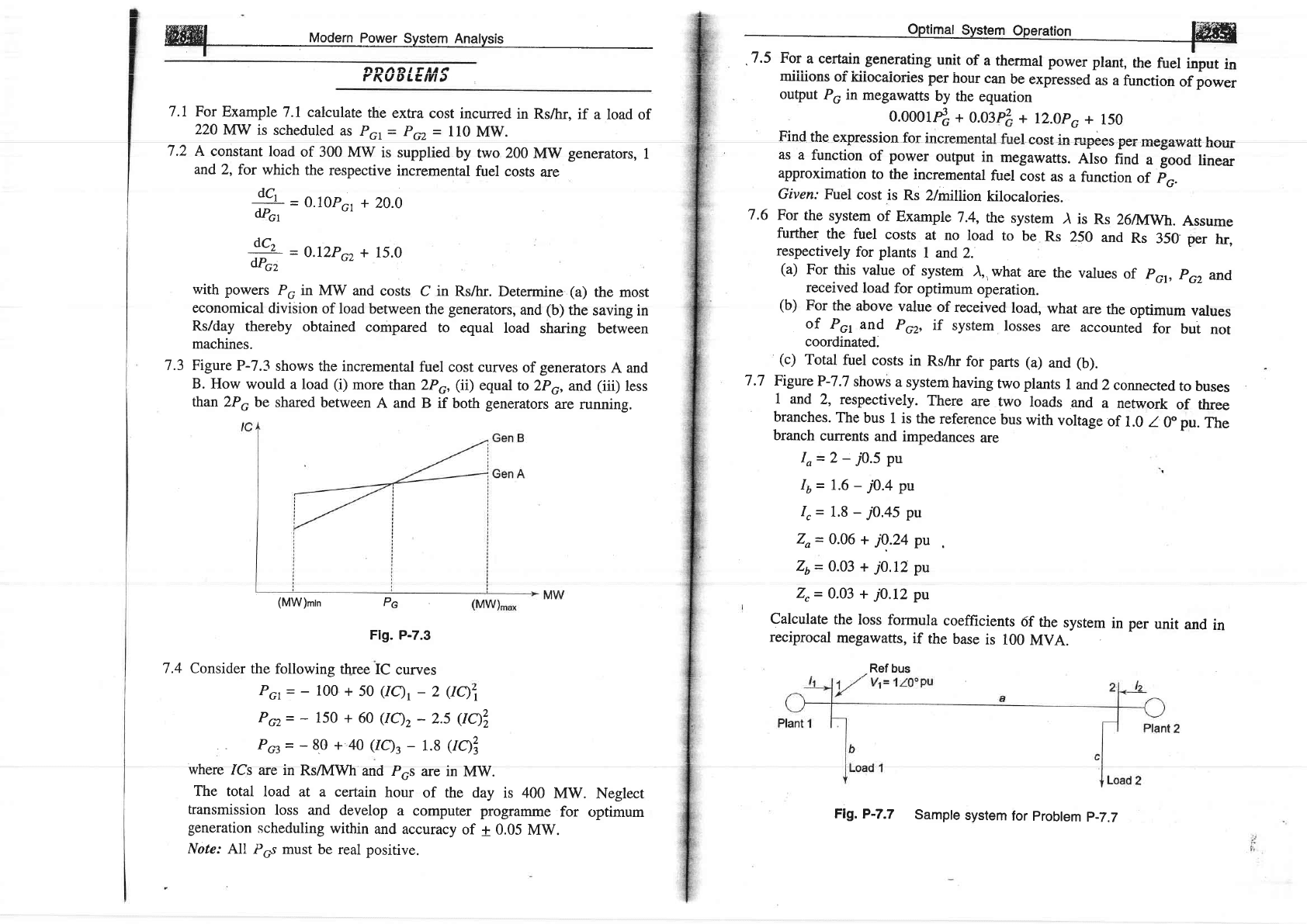
7.3 Figure
P-7.3
shows
the incremental
fuel
cost curves
of
generators
A
and
B.
How
would
a load
(i)
more
than ZPo,
(ii)
equal
to 2p6,
and
(iii)
less
than
ZPo
be shared
between
A and B
if both
generators
are
running.
(MW)mtn
P6
Flg.
P-7.3
7.4 Consider
the
following
three
IC
curves
PGr=-100+50(IQt-2Aqi
Pcz=
-
150
+ 60
(IQz
-
2.5
AqZ
Pct=
-
8.0 + 4a
Qq3
-
1.8
Aqi
where
ICs
are in
Rs/IVIWh
and P6s
are in
MW.
The
total
load at
a certain
hour
of the day
is 400
MW.
transmission
loss and
develop
a
computer programme
for
generation
scheduling
within
and accuracy
of + 0.05
MW.
Note: All
P6s must
be
real
positive.
Neglect
optimum
Hffiffi
miiiions
of iriiocaiories
per
hour
can
be
expressed
as
a
function
of
power
output
Poin
megawatts
by the
equation
0.00014
+
O.$ft
+
r2.0po+
150
Find
the expression
for
ineremental
fuel
eost
in
rupees
per
megawatt
hour
as
a function
of
power
output
in
megawaffs.
AIso
find
a
good
linear
approximation
to the
incremental
fuel
cost
as
a
function
of
Fo.
Given:
Fuel
cost
is
Rs
Zhmltion
kilocalories.
7.6
For
the
system
of
Example
7.4,
the
system
) is
Rs
26a4wh.
Assume
further
the
fuel
costs
at
no
load
to
be
Rs
250
and
Rs
350
per
hr,
respectively
for
plants
I and
2.
(a)
For
this
value
of
system
),, what
are
the
values
of
p61,
po,
and,
received
load
for
optimum
operation.
(b)
For
the
above
value
of
received
load,
what
are
the
optimum
values
of
Pot
and
Por,
if
system
losses
are
accounted
for
but
not
coordinated.
(c)
Total
fuel
costs
in
RsArr
for parrs
(a)
and
(b).
7.7
FigureP-7.7
shows
a system
having
two plants
I and
2
connected
to buses
1 and
2, respectively.
There
are
two
loads
and
a
network
of three
branches.
The
bus
1 is
the
reference
bus
with
voltage
of
1.0
I
0"
pu.
The
branch
currents
and
impedances
are
Io=2
-70.5
pu
L=16- iO4nrr
-o
1,
=
1.8
-
i0.45
pu
Zo=
0.06
+
j0..24
pu
Zt
=
0.03
+
J0.12
pu
Z,
=
0.03 +
/0.I2
pu
Calculate
the
loss
formula
coefficients
6f
the
system
in
per
unit
and
in
reciprocal
megawatts,
if
the
base
is
100
MVA
Ref
bus
Flg.
P-7.7
Sample
system
for
probtem
p-7.7
W
uoo"rn
po*",
syrt"r
Anutyri,
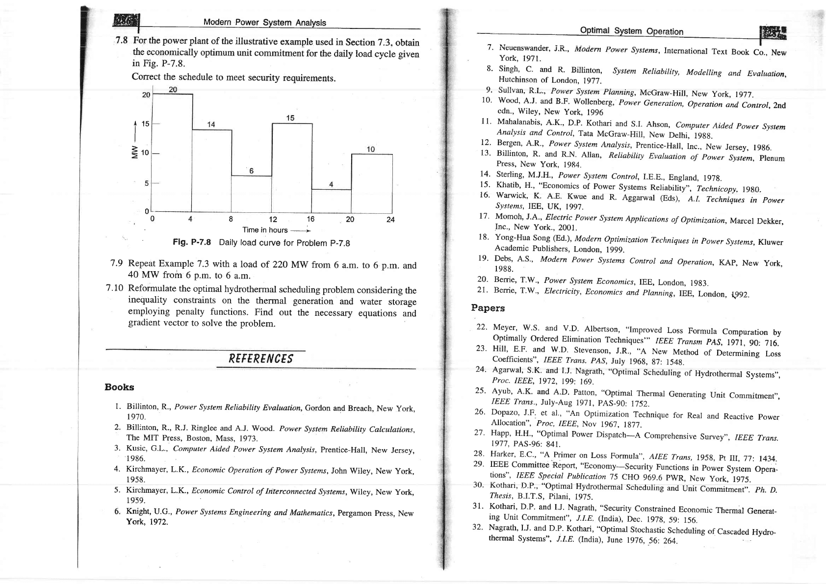
7.8 Fot
the
power
plant
of the
illustrative
example
used
in
Section
7.3.
obtain
the
economically
optimum
unit
commitment
for
the
daily
load
cycle
given
in
Fig.
P-7.8.
Correct the
schedule
to
meet
security
requirements.
812 16
20
24
Time in
hours
---------'
Flg.
P-7.8
Daily
load
curve
for
problem
p-7.9
7.9
Repeat
Example
7.3
with
a load
of 220
Mw
from
6 a.m.
to
6
p.m.
and
40
MW from
6
p.-.
to
6 a.m.
7.10
Reformulate
the
optimat
hydrothermal
scheduling problem
considering
the
inequality
constraints
on the
thermal
generation
and
water
storage
employing
penaity
functions.
Find
out
the
necessary
equations
and
gradient
vector
to solve
the
problem.
REFERE
N
CES
Books
1.
Billinton,R.,
Power
System
Reliability
Evaluation,
Gqrdon
and
Breach,
New
york,
t970.
Billirrton,
R.,
R.J. Ringlee
and
A.J.
Wood.
Power
System
Reliabitity
Calculations,
The
MIT Press,
Boston,
Mass,
1973.
Kusic,
G.L.,
computer
Aided
Power
system
Analysis,
prentice-Hall,
Nerv
Jersey,
1986.
Kirchmayer,
L.K.,
Economic
operation
of Power
systems,
John wiley,
New
york,
I9)6.
Kirchmayer,
L.K.,
Economic
control of
Interconnected
systems,
wiley,
New
york,
1959.
Knight,
u.G.,
Power
systems Engineering
and
Mathematics,
pergamon
press,
New
York.
1972.
i"
E,o
2.
5.
4.
5.
0
w
/.
r\cuenswanoer,
J.}(-,
Modern
power
systems,
International
rext
Book
co.,
New
York,
1971.
8'
singh,
c.
and
R.
Billinton,
system
Reliabitity,
Modelling
and
Evaluation,
Hutchinson
of London,
1977.
9.
sullvan,
R.L.,
power
system
pianning,
McGraw-Hil,
New
york,
1977.
10'
Wood,
A'J'
and
B.F'
Wollenberg,
Power
Generation,
operation
and
Control,
Znd
edn.,
Wiley,
New
york,
1996
11'
Mahalanabis,
A.K.,
D.p.
Kothari
and
s.I.
Ahson,
computer
Aided
power
system
Analysis
and
control,
Tata
McGraw-Hill,
New
Delhi.
r9gg.
12.
Bergen,
A.R.,
power
system
Anarysis,
prentice-Hall,
rnc.,
Ncw
Jersey,
19g6.
13'
Billinton,
R.
and
R.N.
Allan,
Reliability
Evaluation
of
power
System,
plenum
Press,
New
york,
1984.
14.
Sterling,
M.J.H.,
power
System
Control,I.E.E.,
England,
197g.
15.
Khatib,
H., "Economics
of
power
systems
Reriability,',
Technicopy.
r9g0.
16.
warwick,
K.
A.E.
Kwue
and
R.
Aggarwar
(Eds),
A.r.
Techniques
in
power
System.s,
IEE,
UK,
1997.
17.
Momoh,
J.A.,
Electic
power
System
Applications
of
Optimization,Marcel
Dekker,
Inc.,
New
York.,
2001.
18'
Yong-Hua
Song
(Ed.),
Modern
optimization
Techniques
in
power
Systems,Kluwer
Academic
Publishers,
London,
1999.
19'
Debs,
A.S.,
Modern
power
systems
contror
and
operation,
KAp,
New
york,
1988.
20.
Berrie,
T,W.,
Power
System
Economics,IEE,
London,
19g3.
2r.
Berrie,
T.w.,
Electricity,
Economics
and
pranning,
rEE,
London,
rp92.
Dono-o
r
ql,Er;,
22.
Meyer,
w.s.
and
v.D.
Albertson,
..Improved
Loss
Formula
compuration
by
optimally
ordered
Erimination
Techniques',,
IEEE
Transm
pAs,
1971,
90:
716.
23.
Hill,
E.F.
and
w.D.
stevenson,
J.R.,
..A
New
Method
of
Determining
Loss
Coefficients",
IEEE
Trans.
pAS,
July
196g,
g7:
154g.
24'
Agarwal,
S'K.
and
I.J'
Nagrath,
"optimal
Schcduling
of
Hydrothermal
Systems,,,
Proc.
IEEE,
1972,
199:
169.
25'
Aytb,
A'K'
and
A.D.
Patton,
"Optimal
Thermal
Generating
Unit
Commitment,,,
IEEE
Trans.,
July-Aug
1971,
pAS_90:
1752.
26'
Dopazo,
J'F.
et
al.,
"An
optimization
Technique
for
Real
and
Reactive
power
Allocation",
Proc,
IEEE,
Nov
1967.
1g77.
27.
Happ,
H.H., "optimal
power
Dispatch-A
Comprehensive
survey,,,
IEEE
Trans.
1977,
PAS-96:
841.
28.
Harker,
8.c.,
"A
primer
on
Loss
Formula",
AIEE
Trans,
r95g,
pt
ilr,77:
1434.
29'
IEEE
Commitfee
Report,
"Economy-security
Functions
in
power
-system
opou-
tionS".
IEEE ,snprinl Ptthlirntinn 15 f\rJn oao
(
D\rrD Lr-
,J
vrrv
7w7.w
E YYr\,
l\ew
IorK,
Iyl).
30.
Kothari,
D.p.,
"optimal
Hydrothermal
Scheduling
and
Unit
commitment,.
ph.
D.
Thesis,
B.I.T.S,
Pilani,
1975.
31'
Kothari,
D.P.
and
I.J.
Nagrath,
"security
Constrained
Economic
Thermal
Generat-
ing
Unit
Commitment,,
J.I.E.
(India),
Dec.
197g,
59:
156.
32'
Nagrath,
I.J.
and D.P.
Kothari,
"optimal
Stochastic
Scheduling
of
Cascaded
Hydro-
thermal
Systems",
J.I.E.
(India),
June
1976,
56:
264.
ffi
Modern
power
svstem
Analvsis
22
D^"lL^-
I ^r ^l
../\-r:-^l
t1^-t-^l
^f D --^ri--^
n------
Fr ----rr rnnh
ar
JJ. rvDwrrwtrt
J. vr cl.t
r.,tPtlrrr.u
\.VtlLfUl
Ul I\|jAL;|IYtr
fUWEf fIUW
,
IEDL
lfQnS,
IyO6,
PAS.
87:40.
34. Dommel,
H.w.
and w.F.
Trinney,
"optimal
power
Flow
solution",
IEEE Trans.,
October
1968, PAS.
87: 1866.
35. Sasson,
A.M.
and H.M.
Itlerrill, "Sonne
Applications
of Optimization
Techniques
to Power
System Problems",
Proc.
IEEE,
July
1974,62:
959.
36.
wu, F.
et al.,
"A
Two-stage
Approach
to solving
optimal
power
Flows",
proc.
1979
PICA
Conf.
pp.
126-136.
37. Nanda,
J.,
P.R. Bijwe
and
D.P.
Kothari,
"Application
of Progressive
Optimality
Algorithm
to
Optimal
Hydrothermal
Scheduling
Considering
Deterministic
and
Stochastic
Data",
International
Jountal
of Electrical
Power and
Energy
Systems,
January
1986,
8:
61.
38.
Kothari,
D.P.
et al.,
"Some
Aspects
of
Optimal
Maintenance
Scheduling
of
Generating
lJnits",
"/./.E
(India),
August
1985,
66: 41.
39'
Kothari,
D.P.
and R.K.
Gupta,
"Optimal
Stochastic
Load
FIow
Studies",
J.I.E.
(India),
August
1978,
p.
34.
40.
"Description
and
Bibliography
of Major
Economy-security
Functions-Part
I, il,
and III",
IEEE
committee
Report,IEEE
Trans.
Jan 1981.
pAS-r00,
zlr-235.
41. Bijwe,
P.R.,
D.P., Kothari,
J. Nanda,
and
K.S. Lingamurthy,
.,Optimal
Voltage
Control
using
Constant
Sensiiivity
Matrix",
Electric
Power
System
Research,
Vol.
II, No.
3, Dec.
1986,
pp.
195-203.
42.
Nanda,
J., D.P.
Kothari
and K.S.
Lingamurthy,
"Economic-emission
Load
Dispatch
through
coal Programming
Techniques",
IEEE
Trans.
on Energy
conversion,
vol.
3,
No. 1,
March 1988, pp.
26-32.
43.
Nanda,
J.D.P.
Kothari and
s.c.
srivastava,
"A
New
optimal
power
Dispatch
Algorithm
using
Fletcher's
QP
Method",
Proc.
IEE,
pte,
vol.
136. no.
3, May
1989,
pp.
153-161.
44.
Dhillon,
J.S.,
S.C. Parti
and D.P.
Kothari,
"stochastic
Economic
Emission Load
Dispatch",
Int.
J. of Electric
Power
system
Research,
Yol. 26,
No.
3, 1993,
pp.
179
-
183.
45.
Dhillon,
J.S.,
S.C. Parti
and D.P.
Kothari,
"Multiobjective
Optimal
Thermal Power
Dispatch",
Int.
J. of EPES,
Vol.
16, No.6,
Dec.
L994,
pp.383-389.
46.
Kothari,
D.P.
and
Aijaz Ahmad, "An
Expert
system Approach
to the
unit
commitment
hoblem",
Energy
conversion
and
Management",
vol.
36, No. 4,
April 1995,
pp.
257-261.
47 -
Sen,
Subir, D.P.
Kothari
and F.A
Talukdar, "Environmentally
Friendly
Thermal
Power Dispatch
-
An Approach",
Int.
J. of Energy
Sources,
Vol.
19, no.
4, May
1997, pp.397-408.
48.
Kothari,
D.P.
and A.
Ahmad,
"Fuzzy
Dynamic
Programming
Based
optimal
Generator
Maintenance
Scheduling
Incorporating
Load Forecasting",
in Advances
in
Intelligent
systems, edited
by
F.c. Morabito,
IoS
press,
ohmsha,
1997,
pp.
/.J5
-
/4U.
49.
Aijaz
Ahmad
and D.P.
Kothari, "A
Review
of Recent
Advances
in Generator
Maintenance
scheduling",
Electric
Machines
and Power
systems,
yol
26, No. 4,
1998, pp.
373-387.
50.
Sen
S., and D.P.
Kothari,
"Evaluation
of Benefit
of
Inter-Area
Energy
Exchange
of Indian
Power
System Based
on
Multi-Area
Unit
Commitment
Approach",
Int.
J.
of EMPS,
Vol.26,
No.
8, Oct. 1998,
pp.
801-813.
mal
< |
Qan Q ^-i
n D If
^+L^-j
../\-.:-
-t
vvrr.
u.r
qrrs
v.l .
nuluatl
l,
\_rpl,llllal
Review, "Int.
J.
EPES,
Vol.
20,
No.
52.
Kulkarni,
P.S.,
A.G.
Kothari
and
D.p.
Dispatch
using
Improved
BpNN",
/nf.
3t
-
4_7
53.
Aryu,
L.D.,
S.C.
Chaude
and
D.P.
Kothari,
"Economic
Despatch
Accounting
Line
Flow
Constraints
using
Functional
Link
Network,"
Int.
J. of
Electrical
Machine
&
Power
Systems,
28,
l,
Jan 2000, pp.
55-6g.
54.
Ahmad,
A. and
D.P.
Kothari, "A
practical
Model
for
Generator
Scheduling
with
rransmission
constraints",
Int.
J. of
EMps,
vol.
2g,
Approach
for
No. 2,
Nov.
Thermai
Generadng'tjnir
Commitment-A
7,
Oct.
1998,
pp.
443-451.
Kothari,
"Combined
Econonic
and Emission
J.
of EMPS,
Vol.
28,
No.
l,
Jan 2000, pp.
Maintenance
No. 6, June
2000, pp.
501
-514.
55.
Dhillon,
J.s.
and
D.P.
Kothari, "The
surrogate
worth
rrade
off
Mutliobjective
Thermal
power
Dispatch
hobelm".
EpsR,
vol.
56,
2000, pp.
103-110.
56.
Son,
S. and
D.P.
Kothari,
"Large
Scale
Thermal
Generating
Unit
Commitment:
A
New
Model",
in
The
Next
Genera\ion
of
Electric
Power
(Jnit
Commitment
Models,
edited
by
B.F.
Hobbs
et.
al.
KAp,
,Boston,
2001, pp.
Zll-225-
57. Dhillon,
J.s.,
s.c.
Parti
and
D.p.
\
Kothari
,
,,Fuzzy
Decision
Making
in Multi
objective
Long;term
scheduling
of
Hydrothermal
system,,,
rnt.
t.
oy
erns,
vol.
23,
No.
l, Jan 2001,
pp.
lg-29.
58.
Brar,
Y.s.,
J.s.
Dhillon
and
D.p.
Kothari,
"Multi-objective
Load
Dispatch
by
Fuzzy
Logic
based
Searching
Weightage
Pattern,"
Electric
power
Systems
Research,
Vol.
63,
2002, pp.
149-160.
59. Dhillion,
J.s.,
S.c.
Parti
and
D.p.
Kothari, "Fuzzy
Decision-mgking
in
stochastic
Multiobjective
short-term
Hydrothermal
scheduling,"
Ip,B
proc.tcTD,
vol.
l4g,
z,
March
2fi02, pp
l9i-200.
60'
Kothari,
D.P.,
Application
of
Neural
Netwdrks
to
Power
Systems
(Invited
paper),
Proc.
Int. Conf.,
ICIT
2000,
Jan.
2000,
pp.
62l_626.

R
1.,
8.T
.INTRODUCTION
Power
system operation considcrcd
so far was
under conditions
of stcady
load.
However,
both active
and
reactive
power
demands
are never
steady
and
they
continually
change
with
the
rising
or falling
trend.
Steam input
to turbo-
generators
(or
water
input to hydro-generators)
must, therefore,
be
continuously
regulated
to match the
active
power
demand,
failing
which
the machine
speed
will
vary
with
consequent change
in frequency
whieh
may
be
highly
undesirable*
(maximum
permissible
change
in
power
fiequency
is
t 0.5 Hz).
Also
the excitation
of
generators
must
be continuously
regulated
to match
the
reactive power
demand
with reuctive
generation,
otherwise
the voltages at
various
system
buses may
go
beyond
the
prescribed
limits.
In modern large
interconnected
systems,
manual
regulation
is not
feasible
and therefore
automatic
generation
and
voltage
regulation equipment
is
installed on each
generator.
Figure
8.1
gives
the
schematic
diagram
of load
frequency and
excitation
voltage regulators
of a turbo-generator.
The
controllers
are set for a
particular
operatirrg condition
and
they take care
of
small changes
in load
denrand
without
fiequency
and voltage
exceeding
the
prescribed
limits.
With
the
passage
of time,
as the change
in lcad
demand
becomes large,
the
contrcllers
must
be reset either
nianually
or automatically.
It
has
been
shown
in
previous
chapters
that for small
changes
active
power
is dependent
on internal
machine angle 6
and is inderrendent
of bus voltage:
whiie
bus
voitage
is
dependent
on machine
excitation
(therefore
on reactive
-"-
Change in frequency
causes change
in speed of
the consumers' plant
affecting
production
processes.
Further,
it is necessary
to maintain
network frequency constant
so that
the
power
stations
run satisfactorily
in
parallel,
the various
motors operating
on the
system run at
the
desired
speed, correct
time is obtained
from synchronous
clocks
in the system,
and
the entertaining
devices
function
properly.
caused by
momentary
charge
in generafor
speecl,
tI'r.r.tnr*,-i;;?t;qffi;
;;
excitation
voltage
controls
are
non-interactive
for
small
changes
and
can
be
modelled
and analysed
independently.
Furthermore,
excitation
voltage
eontrol
is
F:tcl :tcfinrr in rrrhinh thc -,ri^r firrro n,rn..r,rhr ^6^,rri-+^-^.1 :- rL^e ^$rL- -^-^--^-
rrr vvrrrvrr
Lrrv
rrrcrJvr
rrlttw
vrJrrJr-(lrrr
urlLUultLtrlcu
r5
llla!
ul
ulc;
ggirtcfalor
field;
while
the
power
frequency
control
is slow
acting
with
major
time
constant
contributed
by
the turbine
and
generator
moment
of inertia-this
time
constant
is
much
larger than
that
of the
generator
tield.
Thus,
the
transients
in
excitation
voltage
control
vanish
much
faster
and do
not
affect
the dynamics
of
power
frequency
control.
Fig.
8.1
schematic
diagram
of load
frequency
and
excitation
voltage
regulators
of
a turbo-generator
Change in load
demand
can
be identified
as:
(i)
slow
varying
changes
in
mean demand,
and
(ii)
fast random
variations
around
the
mean.
The
regulators
must
be dusigned
to
be insensitive
to
thst
random
changes,
otherwise
the
system
will
be
prone
to
hunting
resulting
in
excessive
wear
and
tear
of
rotatins
machines
and control
equipment.
8.2 LOAD FREOUENCY
CONTROL (STNGLE
AREA
CASE)
Let us
consider the problem
of controlling
the
power
output
of
the
generators
of a closely
knit electric
area so
as to
maintz,in
the
scheduled
frequency.
All
the
generators
in
such an
area constitute
a
coherent
group
so
that
all
the
generators
^-^^l
-I
^l----.
-l^----^ L--
-.r- - ^.___: -,
.r
.
speeo
iip
anci siow riowii
togetiier
rnarntarnrng
thelr
reiarrve
power
angies.
Such
an
area is defined
as
a control
area.
Tire boundaries
of
a
coqtrol
area will
generally
coincide with
that
of an individual
Electricity
Board
Company.
To
understand the
load
fiequency
control
problem,
let
us
consider
a single
turbo-generator
system
supplying
an
isolated
load.
I
P+JQ
W
Modern
power
system Analys,s
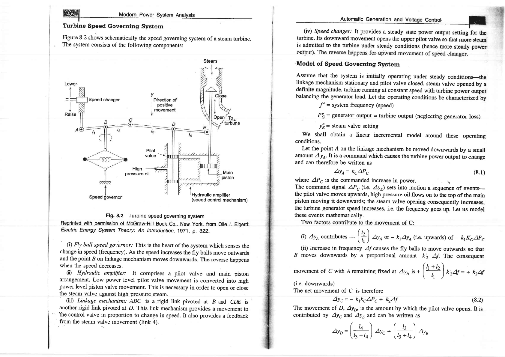
Turbine
Speed
Governing
System
Figure
8.2
shows
schematically
the
speed
governing
system
of a
steam
turbine.
The system
consists
of the
following
components:
Steam
Speed
changer
Main
piston
A
I
rHydraulic
amplifier
(speed
control
mechanism)
Fig.8,2
Turbine
speed
governing
system
Reprinted
with
permission
of
McGraw-Hilt
Book
Co.,
New
York,
from
Olle l.
Elgerd:
Electric
Energy
System
Theory:
An lntroduction,
1g71,
p.
322.
(i)
FIy
ball
speed
governor:
This
is the
heart
of
the
system
which
senses
the
change
in speed
(frequency).
As the
speed
increases
the
fly
balls move
outwards
and
the
point
B
on linkage
mechanism
moves
downwards.
The reverse
happens
when
the
speed
decreases.
G)
Hydraulic
amplifier:
It
comprises
a
pilot
valve
and
main
piston
alrangement.
Low
power
level
pilot
valve
movement
is converted
into
high
power
level
piston
valve
movement.
This
is necessary
in
order to
open
or close
the
steam valve
against
high pressure
steam.
(xl)
Lintcage
mechanism:
ABC
is a
rigid link
pivoted
at
B
and
cDE is
another
rigid
link pivoted
at D.
This
link
mechanism provides
a
movement
to
the control
valve
in
proportion
to change
in
speed.
It also provides
a feedback
,,fr9rn
the steam
valve
movement
(link
4).
turbine.
Its
downward
movement
opens
the
upper
pilot
valve
so
that
more steem
is
admitted
to the
turbine
under
steady
conditions (hence
more
steady
power
.
The
reverse
Model
of Speed
Governing
System
Assume
that the
system
is initially
operating
under
steady
conditions-the
linkage
mechanism
stationary
and
pilot
valve
closed,
stearn
valve
opened by
a
definite
magnitude,
turbine
running
at constant
speed
with
turbin" po*"r
output
balancing
the
generator
load.
Let
the
operating
conditions
be
characteizedby
"f"
=
system
frequency (speed)
P'c
=
generator
output
=
turbine
output
(neglecting
generator
loss)
.IE
=
steam valve
setting
We
shall obtain
a
linear
incremental
model
around
these
operating
conditions.
Let
the
point
A on
the linkage
mechanism
be
moved
downwards
by a small
amount
Aye.It
is a command
which
causes
the
turbine power
output
to change
and
can
therefore
be written
as
Aye=
kcAPc
--t-\
Pilot
value
oil
High
pressure
(8.1)
(8.2)
where
APc
is the commanded
increase
in
power.
\
The
command
signal
AP,
(i.e.
Ayi
sets into
rnotion
a
bequence
of events-
the
pilot
valve
moves
upwards,
high pressure
oil
flows
on to
the
top
of the
main
piston
moving
it downwards;
the steam
valve
opening
consequently
increases,
the turbine
generator
speed
increases,
i.e.
the
frequency goes
up.
Let
us model
these
events mathematically.
Two
factors
contribute
to the
movement
of
C:
(i)
Ayecontributer
-
[?J
Aya
or
-
krAyo(i.e.
upwards)
of
-
ktKcApc
\rll
(ii)
Increase
in frequency
ff
causes
the
fly balls
to move
outwards
so that
B
moves
downwards by
a
proportional
amount
k'z
Af.
The
consequent
movemen
t of Cwith A remaining
fixed
at Ayo
- .
(+)
orO,
-
+
kAf
(i.e.
downwards)
The
net movement
of C is therefore
AYc=-
ktkcAPc+
kAf
The movement
of D, Ayp,
is the amount
by which
the
pilot
valve
opens.
It
is
contributedby
Ayg and
AyB and can
be
written
as
Ayo=(h)
Ayc+(;h)
*,
=
ktayc
+
koAys
(g.3)
The
movement
ay.o-d,epending
upon
its
sign
opens
one
of
the
ports
of
the pilot
valve
admitting
high
pressure'o'
into
thJ
"ynnJ.ithereby
moving
the
main
piston
and
opening
the
steam
valve
by
ayr.
certain
justifiable
simprifying
assumptions,
which
ean
be
rnade
at
this
.tugl,
ur",
(i)
Inertial
reaction
forces
of
main
pistoi
and
steam
valve
are
negligible
compared
to
the
forces
exertecl
on
the
iirton
by
high
pressure
oil.
(ii)
Because
of (i)
above,
the
rate
of
oil
admitted
to
the
cylinder
is
proportional
to port
opening
Ayo.
The
volume
of
oil
admitted
to
the
cylinder
is
thus proportional
to
the
time
integral
o,f
ayo.
The
movement
ay"i.s
obtained
by
dividing
the
oil
volume
by
the
area
of
the
cross-section
of
the-piston.
Thus
Avn=
krfoeayrlat
It
can
be
verified
from
the
schematic
diagram
that
a positive
movemen
t
ayo,
causes
negative
(upward)
movement
ayulccounting
for
the
n"gutiu"
,ign
used
in
Eq.
(8.4).
Taking
the
Laplace
transform
of
Eqs. (g.2),
(g.3)
and (g.4),
we ger
AYr(s)=-
k&cApc(")
+
krAF(s)
Ayp(s)=
kzAyd,s)
+
koAyug)
ayu(g=-ksl
orUn
Eliminating
Ayr(s)
and
Ayo(s),
we
can
write
AY
u(s)
-
k'ktk'AP'
(s)
-
k,krAF(s)
(oo
''
t
')
\
"'tr
,/
-lor,<,r-*^or",].i#)
(8.4)
(8.5)
(8.6)
(8.7)
(8.8)
where
n=
klc
t_
K2
=
speed
regulation
of
the governor
K.,
=
+y
-
gain
of
speed
governor
.r.
l"
,
rs
=
;-;
=
tlme
constant
of
speed
governor
-
KqkS
r--
controt
E
1
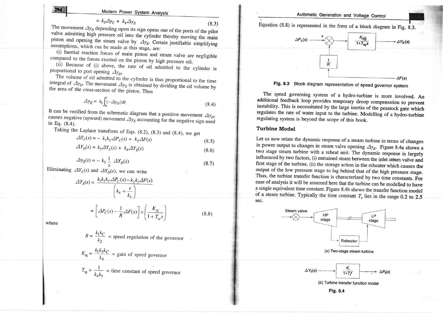
E^,,^ri^- /o o\ :- . r
.
-
t
riyLr.Lru'
\o.o.,
rs
rcpfesenleo
ln
tne
ronn
of
a
block
diagram
in
Fig.
9.3.
4Y5(s)
4F(s)
Steam
valve
-=-&
Flg.
8.3
,Block
diagram
representation
of
speed governor
system
The
speed
governing
system
of
a
hydro-turbine
is
more
involved.
An
additional
feedback
loop provides
temporary
droop
compensation
to prevent
instability.
This
is
necessitated
by
the
targe
inertia
or
the penstoct
gut"
which
regulates
the
rate
of water
input
to
the
turbine.
Modelling
of
a
hyjro-turbine
regulating
system
is
beyond
the
scope
of
this
book.
Turbine
Model
Let
us
now
relate
the
dynamic
response
of a
steam
turbine
in
tenns
of
changes
in power
ouFut
to
changes
in
steam
valve
opening
^4yr.
Figure
g.4a
shows
a
two
stage
steam
turbine
with
a
reheat
unit.
The
dynamic
*ponr"
is targely
influenced
by
two
factors, (i)
entrained
steam
betwein
the
inlet
stbam
valve
and
first
stage
of the
turbine, (ii)
the
storage
action
in
the
reheater
which
causes
the
output
of
the
low pressure
stage
to
lag
behind
that
of
the
high pressure
stage.
'fttus,
the
turbine
transfer
function
is
characterized
by
two
time
constants.
For
ease
of
analysis
it
will
be
assumed
here
that
the
turbinl
can
be
modelled
to
have
Ssingle
equivalent
time
constant.
Figure
8.4b
shows
the
transfer
function
model
of
a sream
turbine.
Typicaly
the
time
constant
{
lies'in
the
range
o.i
ro
z.s
sec.
AYg(s)-FAPds)
(b)
Turbine
transfer
function
model
Flg.
8.4
Ks9
1
+
fsss
(a)
Two-stage
steam
turbine

#ph-Si
rrrroarrn
po*",
s),rt"r
An"ly.i,
I
Generator
Load
Model
The
increment
in power
input
to the generatbr-load
system
is
APG
_
APD
whele
AP6
=
AP,,
incremental
turbine
incremental
loss to
be
negligible)
and
App
is
the
load
increment.
This
increment
in power
input
to
the
syrtem
is
accounted
for
in
two
ways:
(i)
Rate
of
increase
of
stored
kinetic
energy
in
the
generator
rotor.
At
scheduled
frequency
(fo
),
the
stored
energy
is
Wk,
=
H
x
p,
kW
=
sec
(kilojoules)
where
P,
is
the
kW
rating
of
the
turbo-generator
and
H is
defined
as
its
inertia
constant.
The
kinetic
energy
being proportional
to
square
of
speed
(frequency),
the
kinetic
energy
at
a frequency
of
(f
"
+
Arf
)
is
given
by
=nr,(r.T)
Rate
of
change
of
kinetic
energy
is
therefore
$rr*"r
=fffrr"n
(ii)
As
the
frequency
changes,
the
motor
load
changes
being
sensitive
to
speed,
the
rate
of
change
of load
with
respect
to frequ"n.y,
i.e.
arot\ycan
be
regarded
as
nearly
constant
for
small
changes
in
frequency
Af
ard
can
be
expressed
as
Automatlc
Generation
and Voltage
Control
I
=tAP6g)_
aPo(,)r.[#j
(s.13)
2H
Bf"
=
pow€r
system
time
constant
Kp,
=
+
=power
system gain
Equation
(8.13)
can be
represented
in
block
diagram
form
as
in
Fig.
g.5.
laeo(s)
^Po(s)
16---ffioro,
Flg.
8.5 Block
diagram
representation
of
generator-load
model
complete
Block
Diagrram
Representation
of Load
Frequenry
Control
of
an Isolated
Power
System
(8.e)
(8.10)
(8.11)
positivo
for
a
@PDl?flAf=BAf
where
the
constant
B can
be
determined
empirically,
B
is
predominantly
motor
load.
Writing
the power
balance
equation,
we
have
APc-
aP^=THP'
d
(
,r=
-f.]*
<ofl+
B
Af
Dividing
throughoutby
p,
and
rearanging,
we
get
AP(s)=trPn15;
AP6(s)
Flg. 8.6 Block
diagram model
of load
frequency
control
(isolated
power
system)
Steady
States Analysis
The model of
Fig. 8.6 shows
that there are two important
incremental
inputs
to
the load frequency
control system
-
APc, the change in speed changer
setting;
and
APo, the change
in load demand. Let
us
consider,,.4,.simple
situatiqn in
AP6$u)-
AP;q;u)=
1d
/A'^ ' n'7'---\
f
dt
(Afi
+ B(ptt)
af
(8.i2)
Taking
the
l,aplace
transforrn,
we can
write
AF(s)
as
4Fis;
-
AP,G)
-4PoG)
B*-'-
s
Modern
which
the sneerl .hqnrro' hoo ..
g.-.^)
^-.-.
r.han.,oo
't::;
;-::--::^
'(rr
cr
rr^tr(r
ucttrng
\7'e'
af
c
=
o)
and
the
load
demand
:,:il?: ; 3l i: T: ::
a2
rr
e
e
g
o,,
*
;,
2
;
;;
;*;:r;;ffi;
*'
#ff:Tiil:
steady
change
in
system
frequen-cy
for
a
sudd.n
.hung",
ffi;ffi"ffi;ti'l;
anaount
*,
(,
e.Apog):+)is
obtained
as
follows:
aF@)l*,(s):o
:
-
AP^
^f
K I(=1
r^sorr,
. I
It
is
also
rccognized
that
Ko,
=
in
frequency).
Now
4=-(#6)o,.
7/B,whereB-Y^
ai
/P' (in
Pu
MWunit
change
(8.16)
fi
roa
(J
L
8.
rog
.c
102
at
li\ dA^t | |
\r,,
ruu-lo
Loao
(ii)
60%
Load
101
100
0
Percent
Load
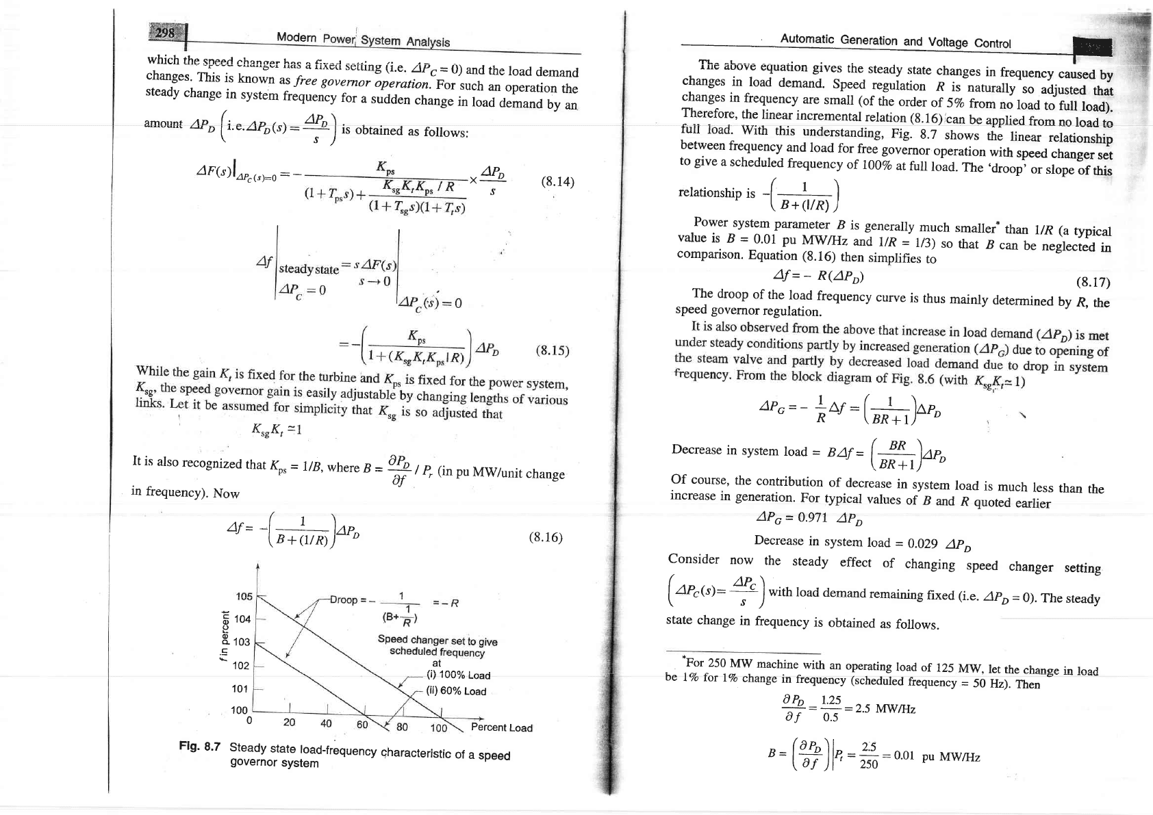
Flg.
8.7
Steady
"*-l?39-frequency
qharacteristic
of
a
speed
governor
system
.rL^
^L^--^
I
r'E
.1uuy'
cquauon
glves
tne
steady
state
changes
in
frequency
caused
by
changes
in
load
demand.
Speed
regulation
R
is-naturally
so
adjusted
that
changes
in
frequency
are
small (of
the
order
of
5vo
from
no
load
to ruu
load).
Therefore,
the
linear
incremental
relation
(g.16)ican
be
applied
from
no
load
to
full
load'
with
this
understanding,
Fig.
8.7
shows
the
linear
relationship
between
frequency
and
load
for
free
governor
operation
with
speed
changer
set
to
give
a
scheduled
frequency
of
r00%
at
full
toao.
The
.droop,
or
slope
of
this
(
relationship
is
-l
I
'l
-
\
B+(t/R)
)
Power
system
parameter
B
is generaily
much
smalrer*
than
r/R
(a
typical
value
is
B
=
0.01
pu
Mwalz
and
l/R
=
U3)
so
that
B
can
be
neglected
in
comparison.
Equation
(8.16)
then
simplifies
to
rhe
droop
"r,,fl",
fjfli;],
curve
is
speed
governor
regulation.
(8.17)
thus
mainly
determined
by
R,
the
MW.
let
the
change
in
load
=
50
Hz).
Then
ap,=_
*"r:
(r^;)o",
Decrease
in
system
load
=
BAf=
(uffi)*,
Of
course,
the
contribution
of
decrease
in
system
load
is
much
less
than
the
increase
in generation.
For
typical
values
of
B
and
R quoted
earlier
APo
=
0.971
APo
Decrease
in
system
load
=
0.029
ApD
consider
now
the
steady
effect
of
changing
speed
changer
setting
(Or"<rl-
+)with
load
demand
remaining
fixed (i.e.
Apo=
0).
The
sready
state
change
in
frequency
is
obtained
as
follows.
*For
250
MW
machine
with
an
operating
load
of
125
be
i%o
for
IVo
change
in
frequency
(scheduled
frequency
a-:?:r?:
:2.5
NNVtHz
af
0.s
:
#:
o'ol
Pu
Mwgz
'=(#)b
W
uodern Power system
Analysis
I
AF@lap,{s):o:
rt v(
ttsgttf t^ps
AD
xu'c
(8.18)
s
(1+
T,rs)(l*
4s)
I
4,flr*uoyro,":
I
AP',:g
xl-
_t
(1
K
\
I
-l
rl
p,
/R
AP,
*
zors)
+
KseKt
KreKrKp,
+ K.sKtKps
/ R
(8.1e)
(8.20)
If
KrrK,
=l
Ar=
(
|
\rc"
"
\
B+llR)
If the speed
changer setting is changed
by
AP, while
the load demand
changes by APo, the
steady frequency
change
is obtained by superposition,
i.e.
(8.21)
According to
Eq.
(8.2I)
the frequency
change
caused by
load demand
can be
compensated by
changing
the setting of the
speed
changer, i.e.
APc-
APo, for Af
=
Q
Figure
8,7
depicts
two load
frequency
plots-one
to
give
scheduled
frequency at I00Vo
rated
load and the other
to
give
the same frequency
at
6O7o
rated
load.
A 100 MVA synchronous
generator
operates
on full
load at at frequency
of 50
Hz.
The load is suddenly
reduced to 50 MW. Due
to time
lag in
governor
system, the steam
valve begins
to close after 0.4 seconds.
Determine
the
change
in
frequency that occurs
in this time.
Given
H
=
5
kW-sec/kVA
of
generator
capacity.
Solution
Kinetic
energy stored in
rotating
parts
of
generator and turbine
=
5
x
100
x
1.000
=
5
x
105
kW-sec
Excess
power
input
to
generator
before
the steam
valve
begins
to
close
=
50
MW
Excess energy input
to rotating
parts
in 0.4
sec
=
50
x
1,000
x
0.4
=
20,000
kW-sec
Stored
kinetic
energy oo
(frequency)2
Frequency
at the end of 0.4
sec
=
5o
x
I
soo,ooo
+
zo,ooo
)t"=
5r
rfz
\
500,000
)
Ar
=
(
".
ru)
'o"
-
APo)
Autor"tic
G"n"r"tion
and
Volt"g"
Conttol
F
Two
generators rated
200
MW and
400 MW
are operating
in
parallel.
The
droop
characteristics
of
their
governors
are 4Vo and 5Vo,
respectively from
no
load
to full
load.
Assuming
that
the
generators are operating
at 50
Hz
at
no
load,
how
would a
load
of 600
MW be
shared
between
them?
What will be
the
system
frequency
at this
load?
Assume
free
governor
operation.
Repeat
the
problem if
both
governors have
a droop
of 4Vo.
Solution
Since
the
generators are in
parallel,
they will
operate
at the same
frequency
at
steady
load.
Let load
on
generator 1
(200
MW)
=
x MW
and
load
on
generator 2
(400
MW)
=
(600
-
x)
MW
Reduction
in
frequency
=
Af
Now
af_
x
af
600-x
Equating
Af
in
(i)
and
v-
600-
x=
System
frequency
=
50
-
0'0-1150
x
231
=
47 .69
Hz
'
200
It is observed
here
that
due
to difference
in
droop characteristics
of
governors,
generator
I
gets
overloaded
while
generator
2 is
underloaded.
It easily
follows
from
above
that if both
governors
have
a droop of.4Vo, they
will
share
the load
as
200 MW
and
400
MW respectively,
i.e. they are loaded
corresponding
to
their
ratings.
This indeed
is desirable
from operational
considerations.
Dynamic
Response
To
obtain
the dynamic
response
giving the
change in frequency
as
function of
the
time
for a
step
change
in load,
we must
obtain the
Laplace inverse
of
Eq.
(8.14).
The
characteristic
equation
being
of
third order,
dynamic
response
can
r' r | 1-!-- - I f-,- - -^^^tC: ^ ---*^-:^^1 ^^^^ tI^.-,^,,^- +L^ ^L^-^^+^--i^+in
Onfy
Dg ODIalneU
luf
A SPtrUfffU
ll|'llll('llua1'I
Ua1DE.
II(rwsYsIr LfIs
r,Il<ll4ivLsllDrlv
equation
can be
approximated
as first
order
by examining
the relative
magnitudes
of
the
time
constants
involved.
Typical
values of the time constants
of
load
frequency
control
system
are rdlated
as
0.04
x
50
200
0.05
x
50
400
(ii),
we
get
231
MW
(load
on
generator
-/A trltf /1 ^-l ^-
JOy
lvlw (IUau
ull
Btrrltrriltur
(i)
(ii)
r)
L)

Trr4T,
<To,
Typically*
t,
=
0.4
sec,
Tt
=
0.5
sec
and
Flg'
8.8
First
order
approximate
brock
diagram
of
road
frequency
controt
of
an isolated
area
Irning
Tro
=
T,
=
reduced
to
thlt
of
F'ig.
AF(s)l*r(s):o
=
Ar
(,)=
-ft{'
-
*,[-,,a[n#)]]
*,
g
22)
Taking
R
=
3,
Kp,
=
llB
=
100,
e,
=
20,
Apo
=
0.01
pu
Af
(t)
=
-
0.029 (I
-
,-t:tt',
Aflrt"udystare =
-
0.029
Hz
0:
Iuld
K*\
=1),
the
block
diagram
of
Fig.
8.6
is
8.8,
from
which
we
can
write
-
to,
.-.
APo
(1+
Kps
lR)+
Zp.s
"
s
-
-
"o{1:-
=xaP,
,l
,+^+ro'1
L
R4,J
Dynamic
response_of
change
in
frequency
for
a
step
change
in
load
(APo=
0.01
pu,
4s
=
0.4
sec,
|
=
0.5
sLc,
Io.
=
2b
sec,
("
=
100,
R=
3)
The plot
of change
in
frequency
versus
time
for
first
order
approximadon
given
above
and
the
exact
response
are
shown
in
Fig.
a.g.
^rirst
order
approximation
is
obviously
a
poor
approximation.
Gontrol
Area
Concept
So far
we
have
considered
the
simplified
case
of
a
single
turbo-generator
supplying
an isolated
load.
Consider
now
a
practical
system
with
e
number
of
generating
stations
aird
loads.
It
is
possible
to
divide
an
extended
power
system
(say,
national grid)
into
subareas
(may
be,
State
Electricity
Boards)
in
which
the generators
are
tightly
coupled
together
so
as
to form
a
coherent
group,
i.e.
all the generators
respond
in
unison
to
changes
in
load
o,
,p"rJ
changer
settings.
Such
a
coherent
area
is called
a
control
area
in
which
the
frequency
is
assumed
to
be
the
same
throughout
in
static
as
well
as
dynamic
conditions.
For purposes
of
developing
a suitable
control
strategy,
a control
area
can
be
reduced
to
a
single
speed
governor,
turbo-generator
and
load
system.
All
the
control
strategies
discussed
so far
are,
therefore,
applibable
to
an
independent
control
area.
Proportional
Plus
fntegral
Control
It
is
seen from
the
above
discussion
that
with
the
speed governing
sysrem
installed
on
each
machine,
the
steady
load
frequency
charartitirti"
fi
agiven
speed
changer
setting
has
considerable
droop,
e.g.
for
the
system
being
used
for
the
illustration
above,
the
steady
state-
droop
in fieo=ueney
will
be
2.9
Hz
[see
Eq.
(8.23b)l
from
no
load
to
tull
load
(l
pu
load).
System
frequency
specifications
are
rather
stringent
and,
therefore,
so
much
change
in
frequency
cannot
be tolerated.
In fact,
it is
expected
that
the
steady
change
in
frequency
will
be zero.
While
steadystate
frequency
can
be
brought
back
io
the
scheduled
Time
(sec)------->
-1
t
I
I
o
First
order
approximatiorl
(8.23a)
(8.23b)
"For
a
250
MW
machine
quoted
earlier,
inertia
constanr
,= 4:.2*5
=
=2osec
'
Bf
o
0.01x
50
Il
=
SkW-seclkVA