Kothari D.P., Nagrath I.J. Modern Power Systems Analysis
Подождите немного. Документ загружается.

Tranefer
Fcn
Tranefer
Fcn
1
SS1
Moo"rn
po*b,
syrt"r
Rn"trrri,
.
Ksg
Kps
Tps.s
+
1
Conetant
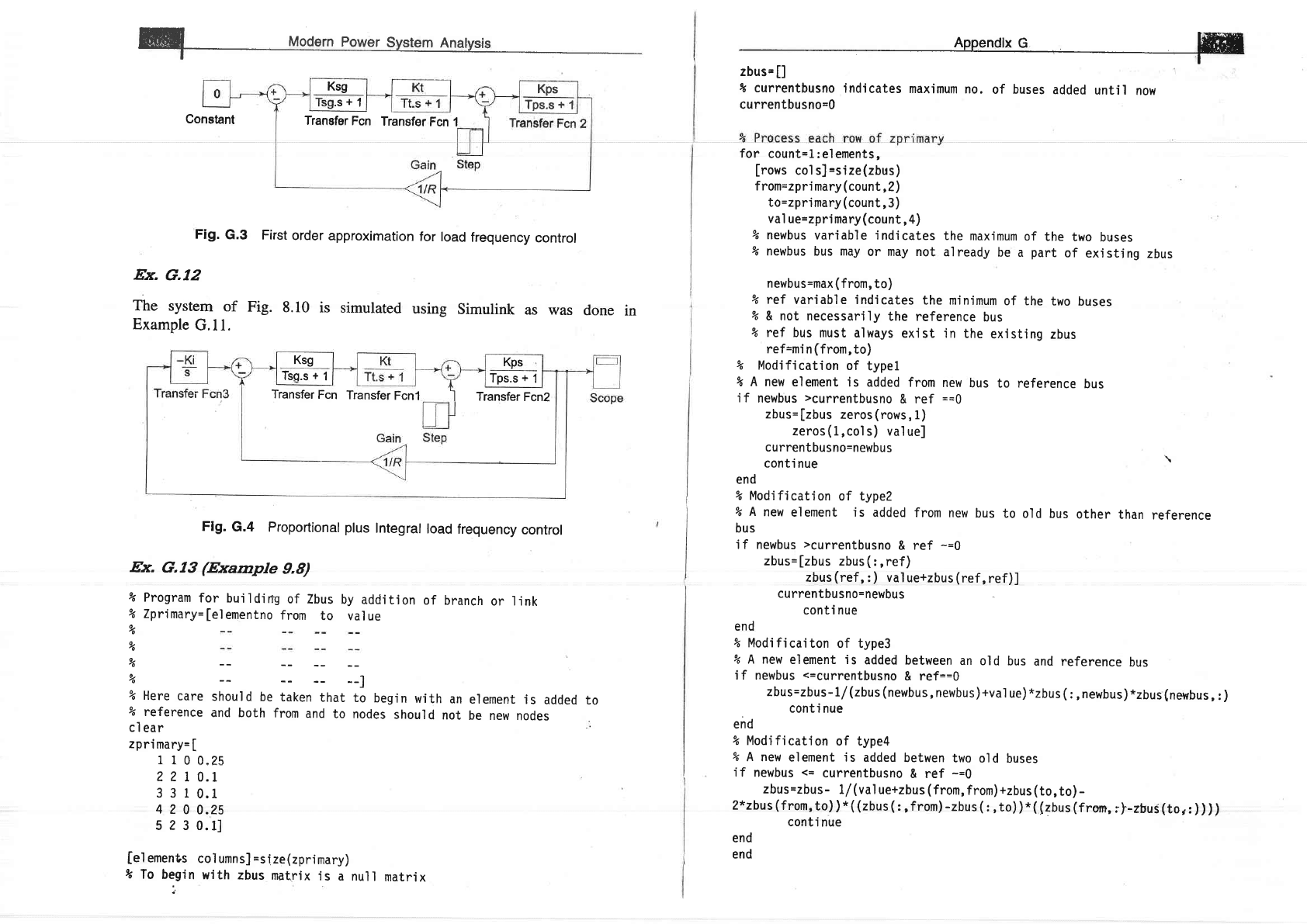
Fig.
G.3
First
order
approximation
for load
frequency
control
Ex.
G.12
The
system
of
Fig.
8.10
is
simulated
using
simulink
as was
Example
G.l l.
Flg.
G.4
Proportional plus
Integral
load
frequency
control
Ex.
G.13
(Example
9.8)
% Program
for
bui]dirrg
of
Zbus
by
addit'ion
of
branch
or l.ink
% Zprimary=[elementno
from
to value
.s+1
done
in
%
%
yo
%
--l
% Here
care
should
be
taken
that
to
begin
with
an
%
reference
and both
from
and
to nodes
should
not
cl
ear
zpri
mary=
[
1 I
0
0.25
2 2
I 0.1
3 3 1
0.1
4
2
0
0.25
s
2
3 0.11
[el
ements
co1 umns]
=size(zprimary)
t
To
begin
with
zbus
matrix
is
a null
matrix
element
is
added
be new
nodes
to
Ksg
Tsg.s
+
1
Kps
Tps.s
+
1
Transfer
Fcn
Transfer
Fcnl
I
Transfer
Fcn2
lffiw
ffiflI
I currentbusno
indicates
maximum
no.
of buses
added
until
now
currentbusno=0
for
count=1:elements,
[rows
co1 s]
=sjze(zbus)
f rom=zpri
mary
(count,
2)
to=zpri
mary
(count,3)
val
ue=zpri
mary
(count,
4)
% newbus
variable indicates
% newbus
bus
may
or may not
newbus=max
(from,
to)
the
maximum
of
the
two
buses
al ready
be
a
part
of
exi sti ng
zbus
bus
to reference
bus
% ref
variable indicates
the minimum
of the
two
buses
%
& not necessarjly
the reference
bus
% ref bus
must always
exist
in the
existing
zbus
ref=mi
n
(from,
to)
%
Modjfication
of
typel
%
A
new element
is
added from
i f
newbus
>currentbusno
& ref
zbus=[zbus
zeros(rows,
1)
zeros(1,cols)
valuel
cu rrentbusno=newbu
s
conti
nue
end
new
==0
%
Modification
of type?
%
A
new
element is
added
from new
bus
to
old bus
bus
i f newbus
>currentbusno
& ref
-=0
zbus=[zbus
zbus(
:,ref)
zbus
(ref,
:
)
val
ue+zbus
(ref,
ref)]
cu rrentbu
sno=newbu
s
conti
nue
\
other
than
reference
end
% Modi fi
cai ton of type3
% A new
element is
added
between
an
old
bus
and reference
bus
i f newbus
<=currentbusno
& ref==O
zbus=zbus-1/(zbus
(newbus,
newbus)+val
ue)
*zbus
(:,
newbus)
*zbus
(newbus,
:
)
conti nue
end
% Mod'ificatjon
of type4
%
A new
element is
added
betwen
two
old buses
i f
newbus
<=
currentbusno
& ref
-=0
zbus=zbus
-
L/
(value+zbus
(from,
from)+zbus
(to,to)
-
2*zbus(from,to))*((zbus(:,from)-zbus(:,to))*((zbus(from,;|-zbuS(tor:))))
conti
nue
end
end

Wl
uodgin Power System
Rnatysis
Ex.
G.14
(Example
12,10)
t Program
for
trans'ient stabi'lity of single
machine connected
to lnfinite
%
bus this
program
simulates Example
12.10 usjng
point
by
point
method
cl
ear
t-0
tf=0
tfi
nal
=0.5
tc=O. 125
tsteP=9.
95
l4=?
.5?
/(
180*50)
j=2
de1 ta=21..64*pi
/180
ddel
ta=0
time
(
1)
=9
ang(1)=2I.64
Pm=0.9
Pnaxbf=2.44
Pmaxdf=0.88
Pmaxaf=2.00
whi I
e t<tfi nal
,
'if
(t==tf
),
Pam'i
nus=0.9-Pmaxbf*si
n
(del
ta)
Papl us=O.9-Pmaxdf*s'in
(del
ta)
Paav=
(
Pam'i nus+Pap1
us
)
/2
'
Pa=Paav
end
i f
(t==tc),
Pami
nus=0.9-Pmaxdf*si
n
(del
ta)
Papl us=0. 9-Pmaxaf*s
j
n
(del
ta)
Paav=
(Pamj
nus+P aplus)
/2
Pa=Paav
end
if(t>tf
&
t<tc),
Pa=Pm-Pmaxdf*si n
(del
ta)
end
i f(t>tc),
Pa=Pm-Pmaxaf*si
n
(del
ta)
end
t, Pa
ddel ta=cidel
ta+
(tstep*tstep*pa/M)
del
ta-
(del
ta*180/pj
+ddel
ta)
*pi
/180
de'l tadeg=de1 ta*180/P'i
t=t+tstep
pause
time(i
)=1
ang(i)=deltadeg
j=j+1
end
axis([0
0.6
0 160])
Ex. G.15
Here the
earlier
Example
G.l4
is solved
again using SIMULINK.
Before running
simulation
shown
in Fig. G.5
integrater t has to be
initialized
to
prefault
value
of
4
i.e.
4.
Thit can be
done by double-clicking on
integrater
1 block and
changing
the initial
value
from 0 to 6s
(in
radius). Also double click
the switch
block
and change
the threshold
value from 0 to the fault
clearing
time
(in
sec.).
Ex. G.16
(Ex.
12.11)
v"
Th'ts
program
simul
ates
transi ent stab'i
1 i ty of
mul timachi ne systems
% The data
is from Examp'le
12.11
cl
ear al
I
format long
%Step
1 In'itialisation
with load flow and
mach'ine data
f=50;tstep=9.91.
6=[12
9J,
;
Pgnetterm=[
3.25
2.10]'
;
Qgnetterm=[
0.6986
0.3110]'
;
Xg=[0.067 0.10]';
% Note the
.use
of .'
operator
here
%
This does
a
transpose
wjthout
taking the conjugate
of each element
yg=[po'larTorect(1.03,
8.235)
polarforect(1.02,
7.16)]
.'
% n is
no of
generators
other
than sl ack
bus
n=2i
%Step
2
V0coni=cori
(V0);
Ig0=conj
( (Pgnettem+j*Qgnetterm)
.
/UO)
;
Edash0=V0+j
"
(Xg.
*
Ig0)
;
Pg0=rea'l
(Edash0.*conj
(Ig0)
)
;
x1
r=angl e(Edash0)
;
% lnit'ial
isation of
state
vector
Pg r=Pg0;
%
Pg_ro1usl.=PgO;
xZ
r=[0
0],;
xtdot
r=[0 0]
,;
x2dot r=[o o]
,;
xldotrpl
rtl=
[0
0J
'
i
x2dotrpl rtl=
J0
0J
'
i

SStep
3
% Here
in
this
example
we have
not
really calculated
YBus
But-sne
% can
write seParate
Program.
yBusdf=
[
1f986-j*35-6301
0
-0.0681+i*5.1661
-j*11.236
0
0
-0.068l+j*5.
1661
YBuspf=
[
I .3932-j*13.8731
-0.2?I++j*7
.6289
-0.090l+i
*6.0975
%Step
4
0
-0.2214+j*7
.6289
0.5+j
*7
.7898
0
0.
1362-j
*6
.2737f
i
-0.090l+j
*6.0975
0
0.1591=j*6.11681
;
o
f
d]
.o
E
c
.g
o
P
E
o
()
o
c
c
o
.c)
o
.E
o
(u
EL
cL
go
eo,
OC
o'o/-
L
o
ts
F
=
_o
(U
o
c
.9
o
c
(g
L
F
u?
(5
6
IL
.s
o
o
% Set
the
va]ues
for
initial
time t(occurance
of
fault)
and
% tc
is time
at
which
fault
is cleared
t=0;
tc=0.08;
tfi nal
=
1 .0;
r=1;
Edash_r=Edash0
;
Edash_rpl
us
1=Edash0
;
while
t
<
tfinal,
%Step 5
Compute
Generator
Powers
using
appropriate
YBus
%
the
YBus chosen
in the
following
step
is set
according
to the current
%
time
if t
<=
tc
YBus=YBusdf;
else
YBus=YBuspf;end
% Note
that
here
we
obtain
the
currents
iniected at
generator
bus
% by multip'lying
the
correspond'ing
row
of
the Ybus
wjth the
ve\tor
of
%
voltages
behind
the
transient
reactances.
This should
also
jnclude
%
slack
bus
voltage
% and
hence
the
entrY
1 aPPears
%
generator
bus
vo'ltages
I=YBus(2:m+1,:)*[1
Edash
rl;
Pg_r=rea1
(Edash_r.*coni
(I)
)
;
jn
the bus
voltage
vector in addition
to
%Step 6
compute
xldot-r
and
xZdot-r
x ldot_r=x2_r;
for k=1:m,
xZdot-r(
k, 1
)
=
(pi
*f/H
(k)
)
*
(PgO
(
k)
-Pg-r
(
k)
)
;
end
%Step
7
Compute
first state
estimates
for t=t(r+1)
x 1_rp1
us
I
=xl_r+x
ldot-r*tsteP
;
xZ_rpl
us
1=x2_r+x2dot_r*tsteP
;
%Step 8 Compute
first estimates
of
E'-r+1
Edash
rpl us1=abs(Edash0)
.*(cos
(x1-rp1
usl)+i*sin(xl-rpl
usl)
)
;
%Step 9 Compute
Pg
for t=t(r+1)
I=YBus(2:m+1,:)*[1
Edash_rp'l
us 1l
;
Pg_rp'l us1=real
(Edash_rp1
us1.*coni
(I)
)
;
%Step
10 Compute
State-denivatives'at
t=t(r+1)
(I'
L
o)
o
c
(\'
=
o)
E
c
at,
IU
-1,
W Mod"rn
po*",.
sy.t.r
An"ryri,
xldot_rplrtl=J0
0J,i
xZdot_rpl
rrl=10
0J
,
i
for
k=1:m,
Iffi
xldot_rpl
usl
(k,
1)
=x2_rp'l
usl
(
k,
l)
;
x2dot.
rpl
usl
(k;
l)=pi
*f/H
(k)
*
(pqg (
%step
11
compute
average
varues
of
state
derivatives
x
I
dotav_r=
(x
ldot_r+x1dot_rp'l
usl)
/
?.0
;
x2dotav_r= (x2dot_r+xZdot_rp1
usl)
/2.0
;
%step
L2
Compute
fjnal
State
estt'mates
fbr
t=t(r+1)
x
l_rp
l us
1=xl_r+xldotav_r*tstep
;
x2_rpl
uslixZ
r+x2dotav_r*tstep
;
%step
13
Compute
final
estimate
for
Edash
at
t=t(r+1)
Edash_rp1
us
1=abs
(Edash0)
.
*
(cos
(xl_rpl
us
1)
+j
*s
i
n
(xt_rp1
usl)
)
;
%Step
14
Print
State
Vector
x?_r=x?_rpl
usl;
xl_r=xl_rp1
usl;
Edash_r=Edash_rp'l
us
I
;
%Step
15
time(r)=1;
for
k=l:m,
ang
(r,
k)
=
(xt_r(k)
*180)
/pi
;
end
t=t+tstep;
r-r+1;
end
plot(time,ang)
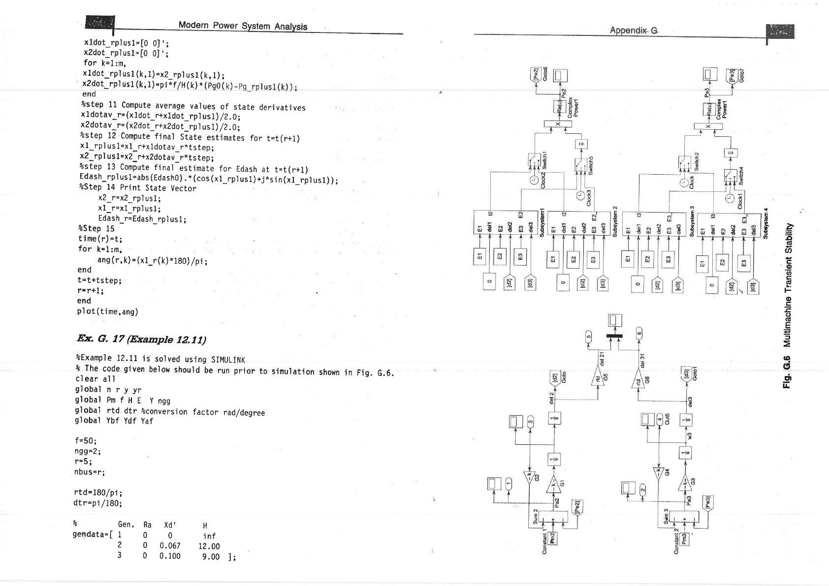
Ex.
G.
17
(Example
IZ,II)
%Example
72.11
iE
solved
using
SIMULINK
%
The
code
given
below
should
be run
prior
to
simu'lation
shown
in
Fig.G.6.
cl
ear
al I
globa1
n
ryyr
globalPmfHE
yngg
global
rtd
dtr
%conversjon
factor
rad/degree
91
obal
Ybf
Ydf
yaf
f=50;
ngg=2;
r=5;
nbus=r;
rtd=180/pi;
dtr=pi
/180i
9o
Gen.
gendata=[
1
2
3
Ra
Xd'
H
0
0
inf
0
0.067
12.00
0
0.100
9.00
l;
EEil$nE
'Fl
88
tt
E
s
3
-8
.=
oll
ct
o
c
.9
U'
c,
6
F
o
.=
.c,
ct
G'
E
=
q
(J
dt
IL
o
o
a
o
.tt
o
N
o
o
o
Il
f
U'
E
o
o
>
6
II
J
6
iltl
Modern Power
svstem Anatvsts
ydf'I
5.
7986-J
*35.6301
0
-0.0681+i
*5.
1661
-
Appendix
G
E
I
Complex
Product
21
E2
0
-j*11.236
0
-0.0681+J*5.1661
0
0.1362-j*6.27371
i
Yaf=
[
1.3932-j*13.8731
-0.22L4+j*7
.6289
-0.0901+j
*6.0975
-0
.22I4+j*7
.6?89
-0.0901+j
*
6 .097 5
0.5+j*7.7898
0
0
0.1591-j*6.11681
;
fct= input('fault
clearing
time fct
=
');
&Dampi ng factors
damp2=O.
0;
damp3=0 . 0;
%I
ni
ti
al
generator
Ang'l
es
d2-0,3377*rtdl
d3=0.31845*rtd;
%Initial Powers
Pn2=3.25;
Pm3=2
. 10;
%Generator Internal
Voltages
El.= 1 .0;
E2=1 .03;
E3=1.02;
%Machine Inertia
Constants;
H2=gendat a(2,4)
t
113=gendata
(3,4)
;
&Machl ne Xd'
;
1661=gendata
(2,3)
;
1661=gendata
(3,3)
;
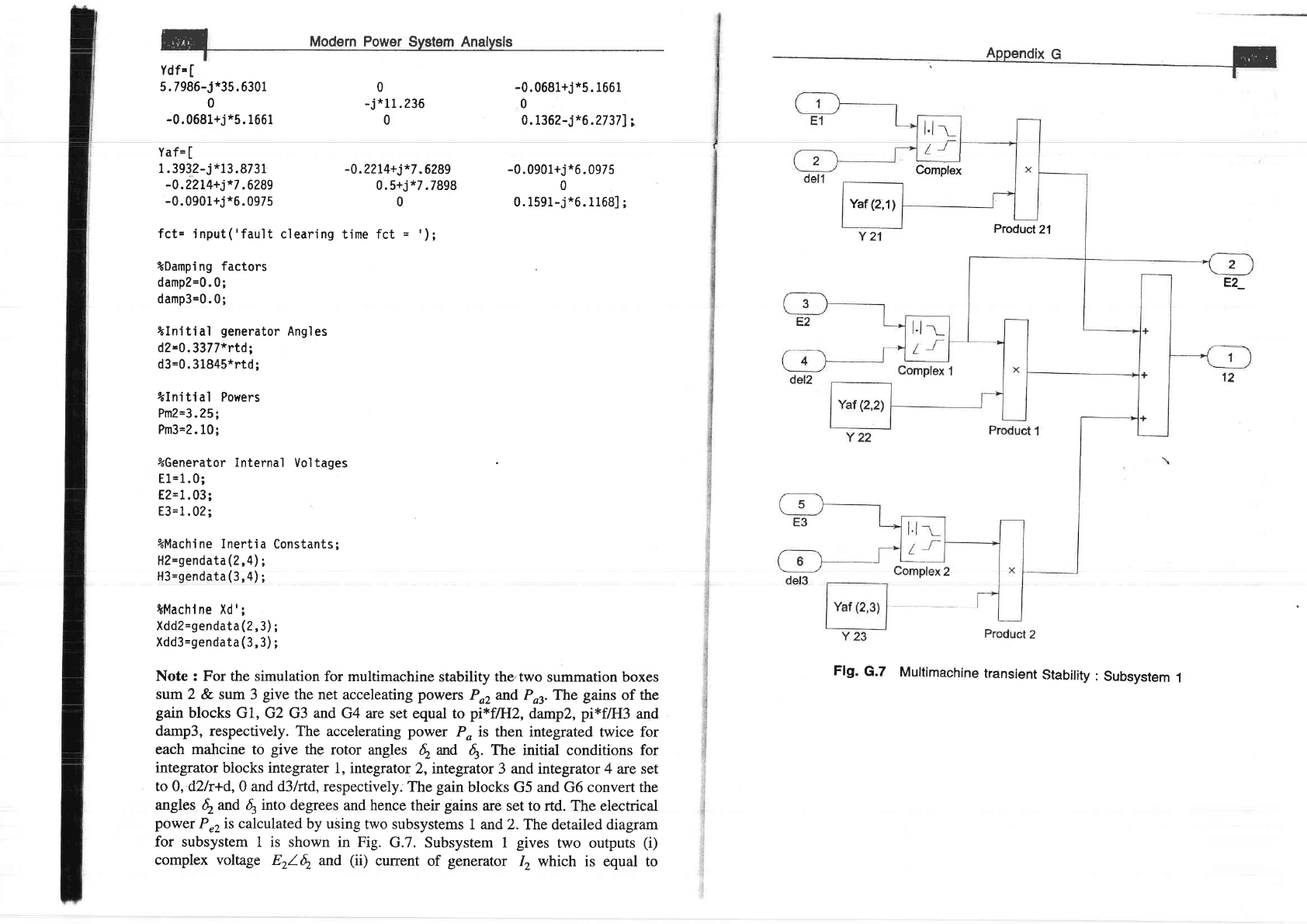
Note : For the simulation
for multimachine
stability
the'two
summation boxes
sum
2 & sum 3
give
the net
acceleating
powers
Po2 and Por. T}ire
gains
of
the
gain
blocks
Gl, G2 G3
and
G4 are
set equal to
pi*fAlZ,
dampZ,
pi*f/Fl3
and
damp3, respectively. The
accelerating
power
P" is
then integrated twice for
each mahcine to
give
the
rotor angles
4
^d
4.
Th" initial conditions for
integrator
biocks integrater
i, integrator
2,integrator
3 anci integrator 4 are set
to
0, d2/r+d, 0 and d3lrtd,
respectively.
The
gain
blocks G5 and G6 convert the
angles
$
and d, into degrees
and
hence
their
gains
are set to rtd.
The
electrical
power
P"2ts calculated
by using
two subsystems
1 and 2.The
detailed diagram
for subsystem
1 is shown in Fig.
G.7. Subsystem
I
gives
two outputs
(i)
complex voltage
Etl6
and
(ii)
current
of
generator
12
which is equal to
Flg.
G.7
Multimachine
transient
Stability
:
Subsystem
1
Yaf
(2,1)
ffi
vodern
power
syster
Rnalysis
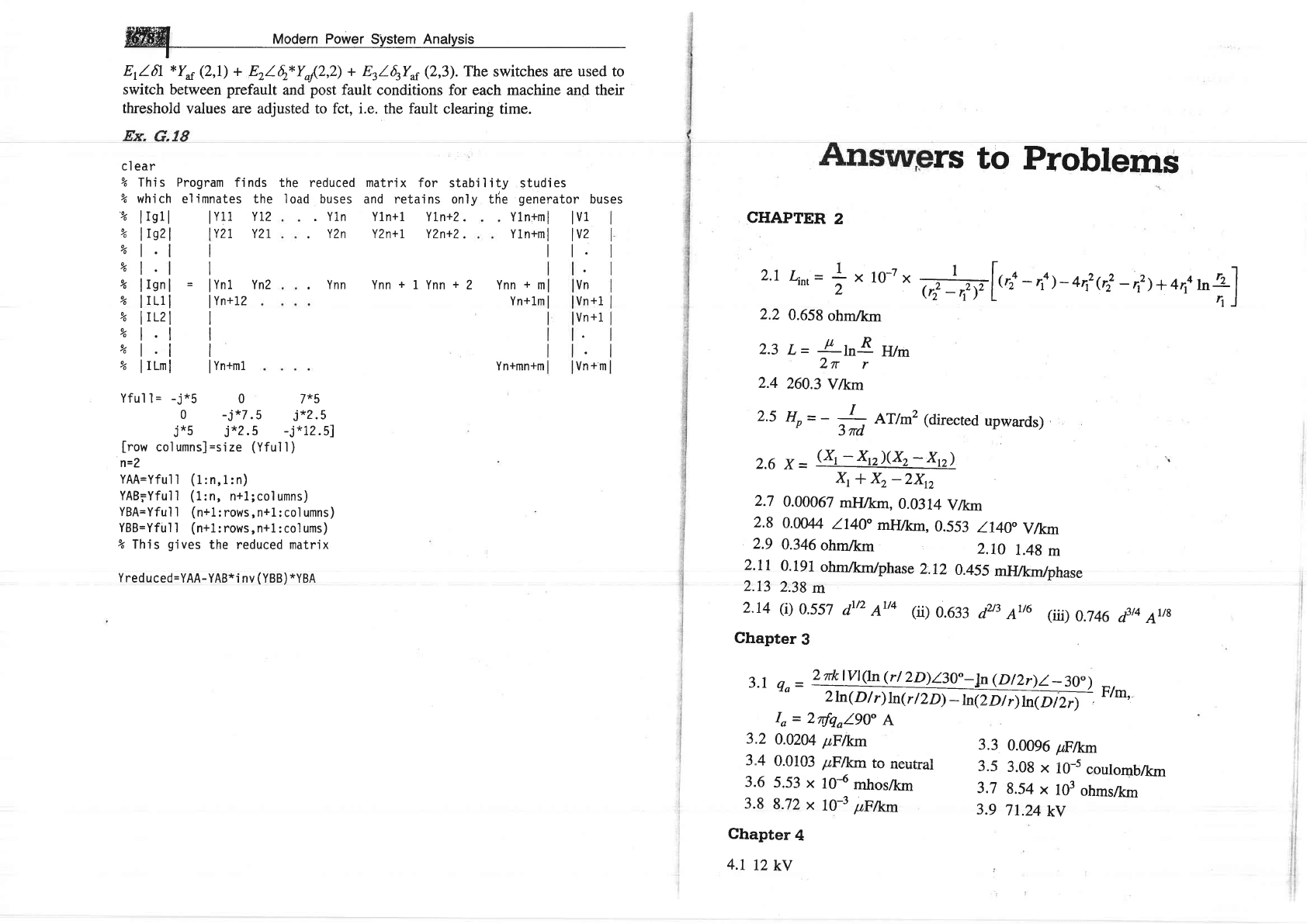
E/-61
*Yar
(2,1)
+ Erlq*Yq{z,z) +
ErlErYar
(2,3).
The
switches are
used
to
switch between
prefault
and
post
fault conditions for each machine and their
threshold
values are adjusted to fct, i.e.
the
fault
clearing
time.
cl
ear
% This
%
which
%
lIgll
%
lIszl
%l.l
vol.l
Yo
llgnl
%
lrLll
yo
lrL2l
%l.l
vol.l
%
lILml
I
I
=
lynl
I
Yn+12
I
I
I
I
I
Yn+m1
Yfull=
_j*5
0
7*5
0
-j*7.5
j*2.5
j*5 j*?.5
-j*12.51
[row
columns]=sjze
(Yfull)
n=2
YAA=Yfull
(1:n,1:n)
YAB;Yfull
(1:n,
n+1;columns)
YBA=Yful
1
(n+1:
rows, n+L:
col umns)
YBB=Yful
1
(n+1:
rows, n+1
: co1 ums)
%
This
gives
the reduced matrix
Yreduced=YAA-YAB*i
nv
(YBB)
*YBA
matri
x for stabi
'l
i ty
and retains only the
Yln+l
YLn+Z.
YZn+l YZn+Z.
Ynn+1Ynn+2
Program
fi nds
el
imnates
the
I
Yll YL?
iIY21.
Y?r
reduced
I
buses
. Yln
.
YZn
.
Ynn
the
I
oad
studi
es
generator
Y1n+ml
I
V1
Yln+ml
I
V2
tl
buses
2.1
Lirt
=
2.2
0.658
ohmlkm
2.3
L=
F
loR
w^
2r
r
2.4
260.3
Vlkm
2.5
He
=
- .,:I
,
AT/mz (directed
upwards)
n
3nd
2.6
X=
(Xt-Xn)(X2-Xn)
\
*
x2
-zxn
2.7
0.00067
m}J/krlt,
0.0314
V/r<Tl
2.8
0.W44
/-t4C,
ml{lkm,
0.553
/.l40
Vlkm
2.9
0.346
ohmtkm
2.rc
1.48
m
2.ll
0.191
ohmlkm/phase
2.12
0.455
mlllkm/phase
2.13
2.38
m
2.14
(i)
0.557
dtt2
Att4 (ii)
0.633
d2t3
A16
er)
0.746
d3t4
Ar/8
Chapter
3
3.1
n^
_
2
rk
lVl(ln (r/
2D)130"_!n
(DlLr)l_30o)
-,
ru
2h(D/r)ln(r/2nffi
t'tm,
Io
=
2rfqo/90"
A
0.0204
p,Flkrrr
O OlO? ttFl1r'm rn na'l.-^r
/r^,rutr
Lv
uvuLl4l
5,53
x
10{
mhoslkm
8.72
x
l0-3
1fi/xm
ro-7
x
*Vlr,:
-,lt-+n,e|
-,,,)+arlr?]
rs
to
Problems
3.3
0.0096
pFlkm
3.5
3.08
x
iO-s
coulomb/km
3.7
8.54
x
103
ohmslkrn
3.9
71.24
kv
CHAPTER
2
YnZ
Ynn+m
Yn+Lm
Yn+mn+m
Vn
Vn
+1
Vn
+1
Vn*m
1
-x
2
3.2
3"4
3.6
3.8
Chapter
4
4.1
12
kV

W
Modrrn
Po*"r.
syrt"t An"lv.i.
Chapter
5
5.1
(a)
992.75 kW
(b)
No
solution
possible
5.2
At
-0.91I.5o,
B'=239.9166.3",
C'=
0.001 1102.6,
Dt
=0.851I.96
(b)
165.44
ky,0.2441-28.3"
kA,
0.808 lagging,
56.49 MW
(c)
7O.8Vo
(d)
28.L5Vo
5.4
(a)
273.5
MVA
(b)
l,IT4
A
(c)
467.7 MVA
5.5 133.92
kV
,
23.12
MW
5.6 202.2
kV
5.7 At
x
=
0,
irr
=
0.3L4 cos
Q,st
-21.7"),
irz=0.117
cos
(utt
+ 109"),
At
x
=
200
km, it
=
0.327
cos
(c..r/
-
9.3o), irz
=
0.t12 cos
(,*t
+
96.6)
5.8 135.817.8o
kV,
0.138115.6o
kA,
0.99
leading,
55.66 MW,
89.8Vo,
373.L1
-
t.5o,
3,338
km, 1,66,900
km/sec
5.g v
-
12g.3172.60,
Y'
-
0.000511g9.5".
2
5.10 7.12",
pfr
=
0.7 lagging,
pfz=
0.74 \agging
5.11 47.56
MVAR
lagging
5.I2
10.97
kV, 0.98 leading,
-
0.27Vo,86.2Vo
5.13 51.16
kV,
38.87 MVAR
leading,
40
MW
5.I4 238.5
kV,
P,+
jQ, =
53
-
jI0,
pf
-
0.983 leading
5"15 17.39
MVAR
leading,
3.54 MW
Chapter
6
6.1 For this
network
tree is
shown in Fig.
6.3a;A is
given
by Eq.
(6.17).
The
matrix
is not unique.
It depends
upon
the orientation
of
the
elements.
6.2
V)
=
0.9721-
8.15"
6.3 V)
=
1.26 l:74.66"
6.a
@)
IE
(b)
j0.3049
j0.1694
j0.1948
j0.3134
0.807
_
js.6s
0.645
_
j4,517
0.968
-
j6.776
0.968
_
j6.776
0.880
_
j6.160
6.5
Pn
=
-
0.598
pu,
PB
=
0.2
pu,
pzs
=
0.796
pu
Qn=
Qzr
=
0.036
pu,
Qn=
Qn=
0.004
pu,
ezz=
ezz=
0.064
pu
6.6
(a)
Pn
=
-
0.58 pu,
P*
=
0.214
pu,
pzl
=
0.792
pu
Qn
=
-
0.165
pu,
ezt
_
0.243
pu,
en
=
0.204
pu
Qy
=
-
0.188
pv,
Qzt
=
0.479
pu,
en=
-
0.321
pu
(b)
Pn
=
-
0.333
Pu,
Pzz=
0.664
pu,
Pr:
=
-
0.333
pu
'
on=
Qzr
=
0'011pu,
QB=
Qzr
=
0.011
pu,
ezt=
en=g.g44
pu
(c)
tz}4
I l-
-ito
s/s3"
i5
I
I
tul
lst87"
-ilo
js
I
J
L
js
js _jl0j
f-iro.rors
j5.o5o5
js
6.7
(a)
(i)
|
;s.osos
-j10
js
L
j5
js
_j10
t
2
3
4
--:-
)
6
7
I
9
U
I
0
0
I
0
0
0
001
-l
00
l-1
0
0-l
0
-l
0l
U
0
I
0
U
Qr
0
I
fh\/i\ D
-n<nn-..
n n A^A
\.r,,
\i,,
i
12:
v.iJVU
pu,
ts13
=
U.LUZ
pu,
pzZ
=
0.794
pu
Qn=
0.087 pu,
Qzt
=
-
0.014
pu
Qn=
QzF
0.004
pu,
Qzz
=
Qsz
=
0.064
pu
//::\ I) t\ .oE
\u,,
f
12:-
u.ooJpu,
Pn
=
0.287 pu,
Pzt
=
0.711
pu
Qn
=
0.047
Pu,Qn
=
0.008
ptr,
Qzt
=
0.051
pu
6.8
Vrt
=
I.025
-
y0.095
=
l.AZ9/.-
5.3. pu
-l
1
0
1
0
4
Mooern
power
slrstem
nnatysii
Chapter
7
7.1
Rs 22.5/hr
7.2
(a)
Pcr
=
140.9
MW,
159.1
MW
7.3
7.4
7.5
7.6
7.8
7.7
S4VlIl$
=
(i)
Gen
A will
share
more
load
than
Gen
B
(ii)
Gen
A and
Gen B
will
share
load
of
po
each
(iii)
Gen
B
will
share
more
load
than
Gen
A.
Pcr
=
148
MW,
Pez,
=
L42.9
MW,
Pct
=
109.1
MW
(dcldPd=0.175Pc+23
(a)
Pq
=
138.89
MW, Pcz
=
150
MW,
Po
=
269.6
MW
0)
Pcr
=
310.8
MW,
Pcz
=
55.4
MW
(c)
For
part (a):
Cr
=
Rs
6,465.141hr
Forpart
(b):
Cr
=
Rs
7,708.15/hr
Bn
=
0.03387 pu
or
0.03387 x
ITa
MW-l
Brz
=
9.6073 x
10-5
pu
or
9.6073 x
10-7
MW-t
Bzz
=
0.02370
pu
or
0.02370
x
10-2
MW-r.
Economically
optimum
UC
Load
(MW)
Unit Number
1234
0-4
4-8
8-r2
t2-16
r6-20
20-24
Optimal
and
secure
UC
Period
Unit
Number
t234
04
4-8
8-12
I2_16
l6-20
20-24
7.9
Total
operating
cost
(both
units
in
service
for24
hrs)
=
Rs
1,47,960
Total
operating
cost
(unit
tr
put
off
in light
load
period)
=
Rs
1,45,g40
1111
r110
1100
1110
1000
1100
20
l4
6
l4
4
10
1111
1'1
1
0
1
1
0
0.
11,1
0
1100
rt00
RL.,-iiiis;E:
lit+i(Atlldt
I--
8.1
Load
on
123
MW,
Load
on
G2
=
277
MW,
50.77
H)..
2
8.2
Af
(t)
=
-
0.029
-
0.04ea.58'
cos (1.254t
+
137.g")
8.3
1/(50K)
sec
9.4
aPtie.
|
-
_
ll
R2)
an
(K
iz+D0
/ K
p,
1
*
K
ipl
+l
/ Rt)+ (K,
r
8.5
APti.,r(s)
=
-
tOOf
O'ztt
t0.9t
L
80s5
1
System
is
found
to
be
unstable.
Chapter
9
9.r
9.2
9.3
it
=
3.14
sin
(314t
-
66.)
+
2.97e
sor,
;"*
=
5A
(a)
81"
(b)
-
9'
(1)
Ie
=
2.386
kA,
.IB
-
9.4
8.87
kA,
4.93
kA
9.6
6.97
kA
9.7
(a)
0.9277
kA
(b)
1.312
kA
(c)
(e)
0.1959
kA
8.319
kA
1.75
kA
(ii)
IA
=
4.373
kA,
IB
=
|.ZS
ta
9.5
26.96
kA
1.4843
kA
(d)
1.0205
kv,
53.03
MVA
9.9
2.39
pu
9.8
9.10
9,12
132.1,
47.9;
136.9,
45.6
gJt
0.6 pu
{
-
-
j8,006
pu,
1{:
=
-
74.004
pu
Chapter
10
10.1 (i)
1.7321270"
(ii)
zl0"
(iii)
1
.7321150.
(iv)
tl2r0"
lO.2
IA=
jl.l6
pu,
Vtn
=
1.171109.5"
pu
ll
-
n O<2 ./ 4.< Ao --- Y'
v
BC
-
v.zirz_-
oJ.+-
pu,
VCB
=
U.9952_Il3.lo
pu.
19
3
Vor
=
l97.Vl-
3.3"
V,
Voz
J
20.Zll51.lo
V,
V"o
=
21.61110.63"
V
10.4
lor
=
19.23_1.
3V
A,
Ioz
=
Ig.23lISV
A,1oo
=
0
A
10.5
1,,=27-87,/3ff
A t,--'t?./- AAo.lo A r n a
^r
^AZ
-
LJ1-
a-'.ZJ
Il,
lA0
=
U
A
Iobr
=
16.1
A,
Iab2
=
7.5/_-75"
A,
Iob1=
l.,S/lS
e,
10.6
Io
=
16.16
+
j1.335
A,
Iu=
_
9.24
_"1\O.AO
e,
Ic
-
-
6.93
+
j9.32
A,
lVN,l
=
lVosl
=
40.75
y
t0.7
1,500.2
w
I
l

ffi4
Modern
Power
System
Anal'sis
Chapter
11
1 1.1
-
i6.56
kA,
lV6,l
-
12.83
kV,
lvobl
=
6.61
kV,
ly"rl
=
6'61
kV
=
I
=
-2./1
(b)
V*=
Vo,
=
0'816
pu, 116l
=
llrl
=
5'69
pu
11.3
(i)
-
i6.2.5
(ii)
-
4.33
(iii)
6'01
(iv)
-
/5
pu
In
order
of
decreasing
magnitude
of
line
currents
the
faults
can
be
listed
AS
(a)
LG
(b)
LLG
(c)
3-Phase
(d)
LL
Il.4
0.1936
ohm,
0.581
ohm,
-
4.33
pu,
j5
pu
11.5(a)3.51pu(b)Vt,=I.|91_159.5"po,V,=I,681|29.8"pt1
(c)
0.726
Pu
11.6
Iu=-Ir=-2.887Pu
||.7
(a)
Iv
=
_
5.79
+
j5.01
kA,
18
=
5.79
+
j5.01
kA,
,IG
= j10.02
kA
(b)
/n
-
-
IY
=
-
6'111
kA,
Ic=
0
1 1.8
In,
=
0
Io^
=
-
73'51
Pu
Ius
=
-
72.08
pu
Ib^=
-
jl.Z
Piu
IrB
=
72.08
pu
I,^
=
-
jl.Z
Pu
11.9
5,266
A
11.10
j2.0
pt
11.1
1
/
=
-
j6.732
Pt,
Io(A)
=
-
i4.779
pu,
/a(A)
=
-
i0.255
po, 1"
(A)
-
-
j0'255
prt
l|lz
0.42
ptt,
-
j9'256
Pu
11.13
-ill.l52
pu,
-i2.478
pu,
-Jl
-239
pn
'1.14
4.737
Pu,
1
Pu
r 1.15
f,
=
-
i12.547
pu, Ifrr(b)
=
-
i0.0962
pu
Chapter
12
l2.I
4.19
MJA4VA,
0.0547
MJ-sec/elec
deg
12.2
4.315
MJA4VA
12.3
40'4
MJiTVIVA
12.4
140.1
MW,
130.63
MW,
175.67
MW
r2.5
72.54
MW
!2.7
L27.3
MW
12.6
4
=
58'
12.8
53'.
We
need
to
know
the
inertia
constant
M
to
determine
/.'
ABCD
constants
61,7
for various
simple
networks
618
in
power
flow
equations
lS9
measurement
of
621
of
networks
in
series
and
parallel
620
AC
calculating
board
lB4
Accelerationfactor
207
Accelerating
power
462
Acid
rain
16
Adjoint
matrix
609
Admittance
matrix
(see
Bus admittance
matrix)
Advanced
gas
reactor
(AGR)
19
Algorithm
for
building
the
Zru,
355
for
load
flow
solution
by
GS
method
205
by NR
method
214
by FDLF
223
for
optimum generation
scheduling
262
for
optimal
hydrothermal
scheduling
280
for optimal
loading
of
generators
on
a
bus 246
for
optimal
load
flow
solution
273
for
short
circuit
current
computation
343
for
short
circuit
studies
349
for static
state
estimation
of
power
systems
540
for
transient
stability,
analysis
of
large
system
4gS
Alternator (sea
Synchronous
machines)
Aluminum
conductor
steel
reinforced
(ACSR)
conductors
52
A *aa a^-+-^1 ^-^- / a ^F\ 4A f,
Arvc
Lrrllll(I
Ellul
\f\\-.8,
JU+
Armature
leakage
reactance
331
Armature
reaction
109,
110,
330
Attenuationconstant
143
Augmented
cost
function
279
Automatic generation
conirol
(see
Load
frequency
control)
Automatic
voltagc
controi
318
Index
12.9
The
system
is
stable
l2.Il
The
system
is
unstable
12.13
The
system
is
stable
12.10
70.54",
0.1725
sec
t2.t2
63.36"
12.14
The
system
is
stable
B-coefficients
261.267
Bad
data
detection
547
Bad
data
detection
547
identification
547
suppression
548
treatment
546
Base
load
3
Base
value
99
Bharat
Heavy
Electricals
Lrd
(BHEL)
14,31
Boiling
water
reactor
19
Breaking
resistors
for
improving
stabiliry
499
Branch
190
Breakers (see
Circuit
breakers)
Brown,
H.
E.
368
Bundled
conductors,
\
capacitivereactance
92
inductive
reactance
68
Bus
generator
198
Ioad
198
PQ
198
PV
198
reference
198
slack
Bus
admittance
matrix
188
formulation
of
187.
189
Bus
impedance
matrix
building
algorithm
355
for
unsymmetrical
fault
analysis
416
in crra*^+-l^^l f^..fr ---!---' -Er
rrr
DJrrrrtlsttrucu
latuil.
al|alysls
JJ
I
Bus
incidence
matrix
I92
Capacitance
^^f^--1^-i--- t -t
u4ruuliluon
oy
memoo
oI
modrlred
geometric
mean
distances
9l
effect
of
earth
on
83
effect
of
non-uniform
charge
distribution
79
effect
of
stranded
conductors
79
line-to-line
78
line-to-neutral
79
12.15
The
system
is
unstable
for
both
three
pole and
single
pole switching

tndex
of
parallel
circuit
three-phase
lines
88
of
three-phase
lines:
with
equilateral
spacing
80
with
unsymmetrical
spacing
81
a two-wire
line
(see
also
Reactance)
78
Central
Electricity
Authority (CEA)
Zg
Charpcteristic (surge)
impedance
l4l
qf
.lines
and
cables
145
Chaiging
current
76, 180
Circle
diagrams
167
Circuit
breakers
327, 329
autoreclose
460
rated
intemrpting
capacity
of
344
rated
momentary
current
of
344
selection
of
344
Circulating
currents
389
Cogeneration
15
Coherent group
291,303
Compact
storage
scheme
189,628
Comparison
of angle
and voltage
stability
592
Compensation
series
779,498,
,Sg
shunt
179,498,562
Compensator
combined
TCR
and TSC
.564
shunt
562
static
synchronous
series
(SSCC)
571
Complex power
105
Composite
conductors
capacitance
9l
inductance
54
Computational
flow
chart
for
load
flow
solution
using
FDLF
227
GS method
20S
NR
method
224
Conductors
ACSR
52
Bundled
52,68
expanded
ACSR
52
iypes
5 i
Conductance
45
Constraints
equality
272,
632
inequality
632
on
control
variables
274
on
dependent
variables
274
for
hydro-thermal
scheduling
.
problems
277
Contingency
analysis
51
rankins
520
screening
520
selection
515
'
direct
method
515
indirect
method
515
Contingency
analysis
by dc
model
520
by
distribution
factors
521
modelling
for
5I4
Contingency
evaluation
(see
contingency
analysis)
Control
area
291,303,306
by
transformers
23I
integral
304
isochronous
305
of
voltage
profile
230
of
WAfiS
and
VARS
along
a
transmission
line
230
optimal
310
parameters
199,272
proportioiral
pft"s-fuBral
303
suboptimal
318
Control
area
concept
303
Control
strategy
303
Control
variables
199,
632
Control
vector
199
Controller
interline
power
flow
(IpFC)
571
interphase
power (IPC)
572
unified power
flow
(UPFC)
571
Converters
567
Ccxrrdinatisn
equations
2fr
Corona
52,68
Cost function
251,270
i,t^e-^^ 1nn
\-ull(i('
L>V
Covariance
matrix
535
Critical
clearing
angle
and
time
467
Current
distribution
factors
265
Current
limiting
reactors
346
DAC
(Distribution
Automation
and
Control
System)
634
Damper
winding
438
DC
network
analyser
39
Data
acquisition
systems
(DAS)
636
Digiral
LF
controllers
322
Direct
axis
reactance
llg
Disturbance
parameters
271,
272
Distribution
factors
generation_shift
SZ0
Iine-outage
520
Diversity
factor
4
Dommel,
H.
W.
270
Doubling
effect
3Zg
Double
line-to-ground
(LLG)
fault
404
Driving
point
(self)
admittance
lg7
Dual
variables
279,632
Dynamic
programming
applied
to
unit
commitment
251
Economic
dispatch
(see
also
optimum
generation
scheduling)
306
Electricity
Board
Zgl
Elements
189
Energy
conservation
3l
Energy
control
centre
637
!MS.(Energymanagement
system)
634
Energy
sources
conventional
13
hydroelectric
power
generation
l7
nuclear
power
stations
lg
thermal
power
stations
13
biofuels
28
biomass
28
gas
turbines
16
geotbermal
power
plants
24
magnetohydrodynam
i
c
(MHDI
generation
23
OTEC
27
renewable
Zs
solar
energy
26
wave
energy
27
wind
power
stations
25
Energy
storage
Zg
fuel
cells
29
hydrogen
Zg
pumped
storage
planf
lg
secondary
batteries
2g
Equal
area
criterion
461
Equal
incremental
fuel
cost
criterion
246
the
medium
length
line
nominal_
zr
representation
l3g
nominal-Trepresentation
137
short
transmission
line
l}g
synchronous
generator
llg
Error
amplifier
3lg
Error
signat
319
Estimation
methods
least
squares
532
weighted
least-squares
533
Estimation
of periodic
components
5g
l
Exact
coordination
equation
26I
Expectation
532
External
system
equivalencing
545
Facrors
affecting
srability
496
FACTS
controllers
569
Failure
rate
255
Fast
breeder
reactor
22
Fast
decoupled
load
flow
223
Fasr
valving
49,9
Faults
balanced
(see
symmetrical
fault
analysis)
calculation
using
Zsus
351,417
open
conductor
414
unbalanced
series
type
397
shunt
type
397
Ferranri
effect
150
Field
erciretion
l0g
Field
rriading
32g
Flat
voltage
starr
205,209,21g
Flexible
AC
transmission
systems
(F-ACTS)
566
Fluidized-bed
boiler
15
Flux
linkages
external
49
internal
46
of
an
isolated
current
carrying
conductor
46
,Fly
ball
speed
governor
Zgz
rorecastlngmethodology
577
Fortescue,C.L.
370,3t6
Frequency
bias
309
Fuel
cost
ofgenerators
243
