Koren Y. The Global Manufacturing Revolution: Product-Process-Business Integration and Reconfigurable Systems
Подождите немного. Документ загружается.

However, significantly increasing the number of fully equipped CNC machines
connected in parallel creates a reverse economy of scale in the system. First, each
CNC machine must include the entire set of tools needed to produce the whole part
even though only one tool operates at a time, meaning that many expensive tools sit
idle as they wait their turn to be used. Second, large magazines of tools must be
attached to each CNC, which increases each machine’s cost. These two points are
amplified when the machines produce several different parts that each requires its own
set of cutting tools.
Paying for unused machining horsepower can also be a cost issue. Whi le high
horsepower might be required for a few operations (e.g., large surface milling), it is
wasted on all the others where it is not needed (such as drilling of holes in the casting,
which requires low power). An additional cost factor is that every CNC machine in the
system must be designed with a wide geometric range of motions to accommodate
the largest and most complex operation needed. These four reasons (a large number of
tools, large tool magazines, high machine power, and machine geometric size)
increase the cost of each CNC machine, and thus the entire cost of the parallel FMS
can become very large.
Case Study—Parallel FMS: At the 1996 International Machine Tool Sho w (IMTS)
in Chicago, Makino demonstrated the full machining of a GM engine block with a single
fi v e-axis CNC machining center. After the initial machining in this demonstration, the
semi-machined block was taken automatically out of the machine, flipped 90
,or180
,
(by a special mechanism), and then inserted back to the machine worktable for continued
machining. The Makino staff in the booth told me that GM bought 96 fiv e-ax es CNC
machines, to be installed at GM plants in a pure-parallel arrangement. Each machine, they
said, could produce an entire engine block or an engine head (except for line boring
operations) in the same way that was demonstrated at IMTS.
These 96 machines were installed at a GM engine plant in Michigan to produce
both engine blocks and heads of a particular six-cylinder engine. That machining
system went into production in early 1998, and had a capacity of 600 engines/day with
a very good uptime. However, the machines were not installe d in a purely parallel
configuration, as the Makino folks announced at IMTS. GM concluded that it was not
practical to machine an entire block or entire head on a single machine in one setup.
For one thing, the part has to be gripped somewhere, and therefore all of its sides
cannot be accessed in one setup.
A single machine doing two setups that are switched using a special dedicated
mechanism is also impra ctical. In fact, it is actually impossible to do it and still
achieve the required precision. Although the fewest possible stations (or setups)
required for machining an entire block or head would be two, this is still only possible
if one can perform engine assembly operations (e.g., inserting valves) as well as
machining operations in the sam e setup. But performing machining and assembly on a
single station is very impractical and risky because one has to find a way to wash the
part and keep it free of contamination before the assembly.
Furthermore, when a complex part is machin ed, some operations must come after
others. In cylinder heads, for example, one must machine a valve seat pocket before
pressing in a powdered-metal valve seat. But machining the valve seat itself can only
THE STATE OF ART AT THE END OF THE TWENTIETH CENTURY 161
be finished after it has been pressed in place. This means that the cylinder head must be
taken off the machine for valve seat insertion, and then put back on a machine for
finish valve machining.
For all these reasons, the GM cylinder machining system was installed in six
parallel lines, each with eight machines to run eight different machining operations
(i.e., eight stages). This system contained 48 of the Maki no machines. GM could run
the system with or without crossover among these parallel lines. Throughput
increased tremendously, however, when crossover was allowed. The engine block
machining system had a similar structure.
The conclusion is that for complex parts with several faces to be machined, a purely
parallel syst em of CNC machines is absolutely impractical. The GM system produced
these engines (blocks and heads) until 2002, when the product was phased out.
To conclude, whether arranged in parallel or not, FMSs are expensive. They are
expensive for several reasons; most particularly because the equipment, which
possesses features enabling general flexibility, is expensive to build and maintain.
They are also expensive in the sense that companies sometimes purchase more
functionality than they really need and the extra functionality is never utilized, or is
only used after several years (see the survey in Section 6.5). Nevertheless, due to
dramatic reductions in the price of CNC equipment in recent years, FMS is still a
frequent optimal choice for produc ing parts in medium to high quantities.
6.3.4 Comparing DML and FMS
DMLs are based on fixed (or hard) automation and produce a single part in very large
quantities. Dedicated equipment tends to be relatively inexpensive to buy and simple
to maintain. However, altering any element of a DML in order to add a new operation
requires a lot of downtime and expense to return the line to optimal efficiency.
Changing the line in order to make a new product will take a couple of years and is
completely uneconomical for runs shorter than several years.
On the other end of the spectrum FMSs are composed of computer numerically
controlled (CNC) machines and other progr ammable automation, and are able to
perform many different operations. FMSs can produce a variety of products on the
same system. The production capacity of FMSs is much lower than that of dedicated
lines and their initial capit al cost is higher. The spectrum of products that are being
produced on FMS is quite large, from optical parts for missiles, to aircrafts, car engine
blocks, and even mass-customized shoes.
The common denominator for both DML and FMS-type systems is that they use
fixed hardware. FMS and CNC operate with fixed software. Although part programs
can be changed on CNC machin es, neither the core software nor the control
algorithms can be altered by the user.
The one practical advantage the DML has over FMSs is throughput. Flexible
machining systems composed of CNC machines are more expensive and slower
compared to dedicated machines, to produce the same number of parts. Consider, as
an example, that on a CNC , a cluster of drilling operations is preformed with a single
tool rather than applying a multi-tool “gang” drilling device such as a dedicated
162 TRADITIONAL MANUFACTURING SYSTEMS
machine could use. Furthermore, even though the CNC is capable of different
machining operations, each one requires a different tool and there is a delay
for each tool change. The distances each tool must travel to and from the tool
changer (i.e., tool positioning) are not a value-added operation and add time to
complete production. These extra motio ns needed for tool positioning and tool
changes make the CNC much slower than dedicated equipment. In contrast, in a
DML, a whole block full of tools might be operating at the same time, performing the
process at very high rates of speed. Because they are slow, more CNC machines are
needed and the entire FMS becomes more expensive than the DML.
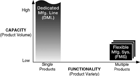
In sum mary, typical DMLs can produce a single part at very high production
volume, and for this reason they can still be efficient for basic work on core products of
the company. In the spectrum of manufacturing systems, DMLs are at the highest
volume per product and the lowest functionality position, as depicted in Figure 6.10.
High functionality means a system includes many functions (and tools) that enable it
to move very quickly from the production of one product to another. This is the area
where FMSs excel. FMSs are highly flexible in converting from one part operation to
another, but because of their slower throughput and higher cost, they are better applied
to those operations that change frequently.
The comparison between the dedicated and flexible systems, shown in Table 6.1,
identifies key limitations in both types of systems.
The workforce skill level required by the two systems is very different. Dedicated,
transfer lines require basic skills from most of the operators. CNC machines (used
in FMS and RMS) require much higher skill levels. FMSs require skilled labor for
(1) loading part programs, (2) changing worn cutting tools in the tool magazines of
the machining centers, and (3) performing maintenance, diagnostics, and repairs on
all components. The operators must possess some familiarity in computers and
a knowledge in operating machines via computer screens, including reading basic
trouble-shooting instructions and reacting accordingly.
Figure 6.10 Volume-functionality spectrum.
THE STATE OF ART AT THE END OF THE TWENTIETH CENTURY 163

The system design focus is perhaps the most important difference between DML
and FMS. A designer cannot just design a dedicated line if the part to be processed is
not given. That means that when considering a DML, the system design focus is on the
part first and foremost. The focus on the part at the design stage enables opportunities
for simultaneous multiple-tool operation (e.g., gang drilling) that, in turn, enhances
system productivity, which creates even more cost-effective DML systems.
In contrast, the design efforts for most FMS are focus on the equipment—standard
CNC machines and robots. Unlike DML stations, CNC machines are not designed
around the part or even a part family. Rather, general-purpose CNCs are built around
a generalized operational envelope, designed before the manufacturer determines the
product to be built. Only when CNCs are selected to make up a system, is process
planning undertaken to adapt the process to the part. In most cases, CNC machine
builders do not know ahead of time what specific applications their machines will be
used for when they design them. That is why flexible systems and machines are
typically constructed with more features than are ever really needed to produce the
parts they will manufacture. Customers, in turn, pay for things that they do not really
need and the extra functionality amounts to a waste of capital.
A serious drawback of the DML system comes from the lead time required for
product design. Basically, a specific product design needs to freeze many months
before production is to begin so that there is time to design and tune the DML. With
product development times shrinking, implementing a DML becomes problematic.
To conclude, Table 6.2 summarizes the main features of DML and FMS as we have
discussed above. Further discussion on convertibility and scalability is presented
below.
System Convertibility is defined as the ease of rapidly adjusting a system’s
production functionality, changing the production of one product to a new one being
introduced to the market. System convertibility must take into account (1) the range of
convertibility of the machines in the system, (2) the arrangement of the machines in
the system, and (3) the material handling devices that connect the machines. As a
rule, better convertibility usually makes the capital investment in a system more
expensive.
Deprived convertibility is a major limiting factor of how quickly new products
can be introduced. For example, in a serial line (Figure 6.11a) the configuration has a
TABLE 6.1 Comparison Between DML and FMS
DML FMS
Limitations Not flexible—for a single part Expensive
Fixed capacity—not scalable Slow—single-tool operation
Advantages Low cost Convertible for new products
Fast—multi-tool operation Scalable capacity
Workforce skills Basic Require computer knowledge
Hardware Fixed Fixed
Software None Fixed
164
TRADITIONAL MANUFACTURING SYSTEMS
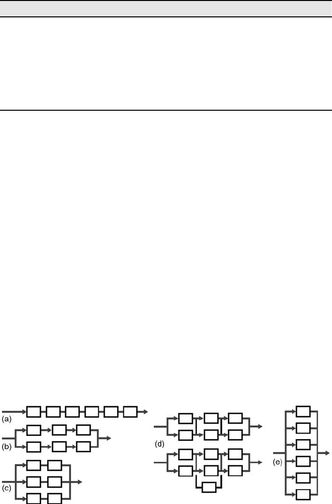
minimum increment of conversion of 1.00 or 100%. That is, in order to introduce a
new product, the entire line must be shut down, changed over, reconfigured (if
possible at all), and restarted. The configuration in Figure 6.11(b), however, can be
partially converted to a new product after only 50% of the machines have been shut
down and reconfigured (a conversion factor of 0.50).
The convertibility of the completely parallel configuration (Figure 6.11e) is the
best; this one can be converted to a little production of a new product after only 16%
of the machines have been shut down and reconfigured. This pure parallel config-
uration is valuable when a company wants to introduce new products to the market
as quickly as possible, and then later ramp up to full production. In contrast, DMLs
do not have any degree of cost-effective convertibility because they are not designed
for change.
System Scalability is defined as the ease of rapidly adjusting production capacity,
or changing a given system’s throughput from one yield to another as needed to meet
changes in market demand. We define system scalability as
System scal ability ¼ 100 smallest incremental capacity in percentage
Scalability is the capacity increment by which the system output can be adjusted to
meet new market demand. For example, in configuration (a) in Figure 6.11 the
TABLE 6.2 Features of DML and FMS
Dedicated FMS/CNC
Structure Fixed Fixed
System design focus Part Machine
Convertibility/flexibility No Yes (general flexibility)
Volume scalability No Yes in parallel FMS
Multi-tool operation Yes No
Productivity High Low
Lifetime investment cost Low Reasonable
when fully utilized for production of many parts
Figure 6.11 Five scalable configurations.
THE STATE OF ART AT THE END OF THE TWENTIETH CENTURY 165

minimum increment of adding production capacity is 100% of the system (i.e., adding
a whole new line); we define its increment as: Scalability ¼ 100 100 ¼ 0%. Thus,
zero scalability means that in order to increase the system capacity beyond its
maximum, the entire line must be duplicated.
Similar calculations show that Configuration b has a scalability of 50%,
Configuration c has 67%, and Configurations d and e have a scalability of
84%. That means that a minimum increment of one sixth of the system—in this case,
one machine—can be added to increase the system capacity (e.g., a machine can be
added to stage 2 of configurat ion d).
Scalable Capacity: Dedicated lines do not have scalable capacity and cannot cope
with large fluctuations in product demand. This challenge can theoretically be met by
FMSs that are scalable, when designed with CNC machines that operate in parallel,
but the economics of implementing a parallel FMS is quest ionable.
The system designers have to weigh the amount of capacity they need to add. For
example, to add capacity to Configuration a, 100% of the equipment would need to be
duplicated. To add to Configuration e, only 16% of the equipment needs to be
duplicated. However, adding any capacity to Configuration a doubles the actual
output. Instantly doubling capacity is rarely appropriate and so, in most cases, is not
justified.
In summary, one can see how system responsiveness—convertibility and scal-
ability—is a critica l concern in a manufacturing system. It plays a key role in gaining
a competitive advantage for a company in the globalization era.
Two of our students, who work at the auto industry, shared their practical
experience:
“The discussion on dedicated manufacturing lines and the comparison to flexible
manufacturing systems matches exactly to my own experience (in 2003). I am working
with three plants to implement a product change. Two sites have FMS-type equipment, and
one site has a dedicated manufacturing line. The difference in cost and time to implement a
change is significant! What can be accomplished in
six months on the FMS equipment will
take 18 months on the DML equipment, and cost much more. But the cost per unit produced
is lowest at the DML site. Therefore, the DML site generates high profits, but only if the
market is stable. The longer changeover could result in lower profit from lost sales.”
—Dan Gulledge
“I have good experience with flexible manufacturing systems and it’s odd to hear of an
FMS as being traditional. But then, if you look into dedicated lines, there is somewhat
a factor of flexibility about them today. I currently (2004) supervise a dedicated line that
produces lost-foam engine block and head castings, and even though that is all we produce,
the tooling can be switched from block to head on each machine. Although the casting
sector is dedicated, it too can be outfitted with the others tooling to produce the opposite
product. Even engine block machining lines are flexible enough to be altered for different
blocks and are just as capable as putting up the numbers as dedicated lines do. I suppose the
differences would be in the tooling to accomplish, such as gorge to mill, but other than that,
systems even 15-20 years old now are flexible somewhat.” Greg Wood
166
TRADITIONAL MANUFACTURING SYSTEMS
6.4 ASSEMBLY SYSTEMS
Assembly systems are utilized in virtually all types of durable goods manufacturing.
There are three basic types of assembly systems: (1) manual assembly, which is
carried out by human assemblers, usually with the aid of simple power tools. This is
the most flexible assembly system, since humans are very “flexible” and can easily
adapt to perform new tasks. This type of assembly is the norm in assembly of any
complex products and especially in automotive final assembly. (2) Assembly systems
that combine human assemblers and automated mechanisms. This type is common in
assembly of mass-customized personal computers as described below. (3) Fully
automated assembly systems for mass-produced parts, and particularly in hazardous
environments such as in welding of auto body panels (an assembly operation).
The invention of programmable industrial robots in the early 1980s accelerated the
development of automated assembly systems.
8
Assembly robots are equipped with
various “end effectors” that can perform simple operations such as inserting screws
and grasping and placing parts. Simple grippers containing two or three fingers can
hold parts and place them in the assembly; more complex end effectors may include an
automatic bolt screwing device or a fast tool-changing device. The geometry and
working-envelope of the robot must fit all members of the particular product family
for which the assembly system is designed. Because robots have CNC-type con-
trollers, multiple task programs may be stored in the controller, and that program is
executed when a particular product of the family is assembled. The robot end effecter
typically must be changed to assemble each different product, similar to tool changes
in CNC machining centers.
A typical automated assembly station has two basic functions: (1) the transfer and
feeding of components into the assembly station and (2) the insertion of components
into the product assembly. In fully automated assembly systems the feeding
mechanisms usually consist of magazines (or buffers) into which the components
are staged, and multiple material-flow sub-systems that feed the components auto-
matically to the assembly station. The actual insertion of the components (i.e., the
assembly itself) is done by assembly robots and automated (often pneumatic)
equipment, aided by sensors. The types of sensors used depend on the application
and include computer vision, force sensing, proximity, and photoelectric sensing.
The design features of the product and its components determine if it can be
assembled on an automated assembly system or if it must be assembled manually.
Note that many products require at least some insertion operations that are too
complex to be automated. Such products must be at least partially assembled
manually.
In multi-station automated assembly systems, pallets carry the product through all
assembly stations (one pallet for each product). The pallets ride on a conveyor along
the conveyor until encountering a stop gate at an assembly station or another pallet.
The product assembly is done sequentially in the stations along the conveyor. An
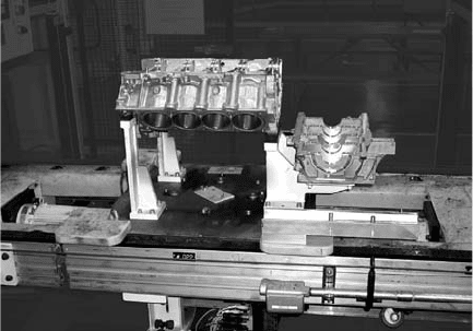
automated assembly station for an engine is shown in Figure 6.12.
Assembly systems are designed in stages where each stage rigidly transmits its
output to the immediate successor stage. There are serial, synchronous assembly
ASSEMBLY SYSTEMS 167
systems, in which the product is partially assembled at each stage, allocating exactly
the same amount of time at every stage. Office chairs, for instance, are assembled
manually on serial synchronous lines of about 20 stations, and the chair stays for
30 seconds at each assembly stage. That means that the line throughput is two chairs
per minute.
But there are other multi-stage assembly systems in which each stage requires parts
that have been assembled from several preceding stages. These complex systems are
asynchronous and usually require buffers between the stages. Figure 6.13 shows
a typical assembly line
*
with assembly stations, M, and buffers, B. The highlighted
stations form the main assembly line, and the others are sub-assemblies that provide
components to the main line stations. For example, three sub-assembly lines feed three
different components to station Ma. The output of station Ma moves to buffer Ba
awaiting transfer to station Mb, where new parts as well as a component from another
sub-assembly line (Mb1 -Bb1) are added on. Station Mb1 is an automated station that
assembles two parts and places the sub-assembly in buffer Bb1. The assembly tasks on
station Mc take very long time. To balance the assembly line flow and ensure even
throughput, three identical assembly stations are arranged in parallel at this stage
(Mc1, Mc2, Mc3). A second buffer Bb distributes output to all three, and buffer Bc
collects them again for the next stage Md. The final assembly station, Me, completes
the product and moves it off the line.
It is common now for personal computers to be custom assembled to satisfy
a customer’s particula r order. The assembly line for these consists of robot s and
automated mechanisms for kitting, testing, and packaging, but people still perform the
actual computer assembly. Because of the huge variety of customer’s orders, human
assemblers are the most practical option to accommodate the various needs.
Figure 6.12 An engine assembly station (courtesy of GM R&D Center).
*
This example, brought by Dr. Wencai Wang, is from the auto industry. Station Mb1 is an automated station
that puts a needle bearing onto a shaft. The other stations in this example are all manual.
168 TRADITIONAL MANUFACTURING SYSTEMS

Figure 6.14, depicts the computer assembly line starting with a series of kitting
stations where trays move along a line and amass the components for each computer
order. Each order has its own tray. A robot selects the desired component at each
station and puts it on the tray in the appropriate order. For example, a robot picks
a particular hard disk from a magazine of several choices and places it on the tray. All
components are selected in the same way. At the end of the kitting line, all the parts
needed for a given order are on the tray, arranged appropriately for assembly. Each
tray is then conveyed to a manual assembly station where two workers, facing each
other, assemble the computer. The topmost component, the computer shell, com es off
first and then each internal component is inserted as required. The time required for
the assembly of each computer order is different depending on the number and type of
components required. To meet demand and to maintain the pace of the serial portion of
the line, there may be 10–20 assembly tables arranged in parallel. When each
assembly is completed, the com puter is sent for automated software loading and
testing stations. When that phase is successfully completed, the computer is put back
on a conveyor, sent to the automated packaging station, and then shipped to the
customer who ordered it. Typically, com puters are rolled out of the assembly syst em at
a rate of 4 seconds each.
Figure 6.14 A typical flexible assembly system for personal computers.
Figure 6.13 A typical multi-stage assembly system.
ASSEMBLY SYSTEMS 169
There are also reconfigurable assembly systems. A key feature of these systems is
a modular conveyor system that can operate asynchronously, and is reconfigurable to
accommodate a large variety of component choices according to the application and
the product being assembled. A reconfigurable conveyor allows quick rearrangement
to alter process flow, adding or bypassing assembly stations according to the desired
product. It also allows for serial–parallel configurations to balance the assembly line
flow as necessary to ensure even throughput. An example of this type of conveyor can
be seen at this reference website.
9
6.5 INDUSTRY EXPERIENCE WITH FMS—A SURVEY
The development of flexible automation enablers (e.g., robots and CNC machining
centers) during the 1970s has resulted in many succe ssful FMS systems since the
1980s.
10
Nevertheless, in the early 1990s we also began to hear about cases of FMS
failure. These stories were not popular, and information about them was not easily
available. One case was reported in Japan, where a large manufacturing company
decided to get rid of its FMS because it was too complex to operate, and its
productivity was much lower than expected. An engine manufacturer in Michigan
bought a flexible machining system composed of 12 CNC machines to augment its
dedicated lines, but after 2 years of unsuccessful attempts to operate the system, the
company got rid of the whole FMS. In another case in Michigan, a well -known system
integrator sold a FMS consisting of 15 machining centers to an engine producer, but
could not achieve the required part quality. It also suffered from greater than expected
downtimes due to operator’s training issues. The system integrator finally had to take
back its system, and the case was settled out of court.
These stories motivated us to investigate the reasons for success and failures of
FMS in the mechanical industries (machine builders, automobile producers, engine
manufacturers, etc.). Our research was based on a survey that was conducted by a
CIRP
*
Working Group on “Flexible Automaton—Assessment and Future” held
jointly with the ERC for reconfigurable man ufacturing systems during fall 2001
through summer 2002.
At that time the manufacturing industry was just starting to face new challenges of
fluctuating markets and the need for production of high quantities of a mix of products
fromthe same product familyon asingle FMS.Inour study, industryexpertswere asked
to evaluate their current FMSs and suggest enabling technologies that were needed to
improve the performance of flexible manufacturing. The survey findings indicated
some valuable results, the most important of which was that reconfigurable
manufacturing systems had emerged as the major operational priority across the board.
We received 27 responses to our questionnaire; 14 responses from companies in the
United States, and 13 from Europe (seven from Germany, four from Italy, and two
*
CIRP is the International Academy for Production Engineering that has headquarters in Paris, France. The
survey was conducted by the Manufacturing Paradigms Working Group of CIRP. The survey leaders were:
Y. Koren in the United States, U. Heisel in Germany, C. Boer in Italy, and D. Dumor in France.
170 TRADITIONAL MANUFACTURING SYSTEMS