John Campbell. Castings Practice:The Ten Rules of Castings.2004
Подождите немного. Документ загружается.

Example (c) is a further development of this
idea, creating lugs that serve the additional
useful purpose of allowing the part to
be clamped immediately over the points of
support, and off the faces that require to be
machined. In practice the lugs may be existing
features of the casting, or they may be additions
for the purpose of allowing the casting to be
picked up for inspection or machining. This
concept is capable of further development, using
lugs arranged on all the centrelines of the casting
so as to halve the errors in all directions.
10.2.2 Cylindrical systems
Most cylindrical parts do not fall nicely into the
classical six-point location systems as described
above for rectilinear components. The errors of
eccentricity and diameter both contribute to a
rather poor location of the centre using this
approach. The unsuitability of the orthogonal
pick-up system is analysed nicely by Swing
(1962).
In fact, the obvious way to pick up a cylinder
is in a three-jaw chuck. The self-centring action
of the chuck gives a useful averaging effect on
any out of roundness and surface roughness, and
is of course insensitive to any error of diameter.
In classical terms, the three-jaw chuck is
equivalent to a two-point pickup, since it defines
an axis. We therefore need four more points to
define the location of the part absolutely. Three
points abutting the jaws will define the plane at
right angles to the centre axis, and one final
point will provide a `clock' location. Figure 10.3
shows the general scheme.
Another location method that is occasionally
useful is the use of a V block. This is a way of
ensuring that a cylindrical part, or the round
edge of a boss, is picked up centrally, averaging
errors in the size and, to some extent, the shape
of the part. The method has the disadvantage
that errors in diameter of the part will cause the
whole part to be shifted either nearer to or away
Figure 10.3 The use of a three-jaw self-centring chuck
for casting location and clamping.
178 Castings Practice: The 10 Rules of Castings
6
4
2
3
3
3
5
4
4
5
4
1
1
1
1
5
2
2
2
5
6
6
6
3
(c) Use of tooling
lugs for clamping
(d) Jig or fixture
attached to mark-out
table or machine tool
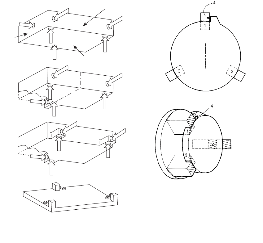
(a) Basic location system
(b) Halving of
length errors
Plane B
Plane A
Plane C
Figure 10.2 (a, b) Increasingly improved ways in which the
six-point location method can be used on a casting.
(c) Further recommended technique using lugs to facilitate
clamping. (d) The jig used as a cradle for the six-point
location system (clamps are omitted for clarity).
from the block, depending on whether the dia-
meter is smaller or larger. (The reader can
quickly confirm these shifts in position with
rough sketches.)
A widely used but poor location technique is
the use of conical plugs to find the centre of a
cored hole. Even if the hole is formed by the
mould, and so relatively accurately located, any
imperfection in its internal surface is difficult
to dress out, and will therefore result in mis-
location. If a separate core forms the hole then
the core-positioning error will add to the overall
inaccuracy of location. Location from holes is
not recommended.
It is far better to use external features such as
the sides of bosses or walls, as previously dis-
cussed. These can be more easily cast and
maintained clean.
10.2.3 Trigonal systems
For some suitable parts of triangular form, such
as a steering gear housing, a useful and funda-
mentally accurate system is the cone, groove
and plane method (Figure 10.4).
10.2.4 Thin-walled boxes
For prismatic shapes, comprising hollow, box-
like parts such as sumps (oil pans), the pickup
may be made by averaging locations defined on
opposite internal or external walls. This is a
more lengthy and expensive system of location
often tackled by a sensitive probe on the
machine tool, that then calculates the averaged
datum planes of the component, and orients the
cutter paths accordingly. This technique is
especially useful where an average location is
definitely desirable, as a result of the casting
suffering different degrees of distortion of its
relatively thin walls.
The tooling points should be defined on the
drawing of the part, and should be agreed by
(i) the manufacturer of the tooling, (ii) the caster,
and (iii) the machinist. It is essential that all
parties work from ONLY these points when
checking dimensions and when picking the part
up for machining.
For maximum internal consistency between
the tooling points, all six should be arranged to
be in one half of the mould, usually the fixed or
lower half, although sometimes all in the cope.
The separation of points between mould halves,
or having some defined from the mould and
some from cores, will compromise accuracy.
However, it is sometimes convenient and correct
to have all tooling points in one internal core, or
even one half of an internal core (defined from
one half of the core box) if the machining of the
part requires to be defined in terms of its inter-
nal features.
Clearly therefore, the location points are
required to be actual cast-on features of the
casting. This point cannot be over-emphasized.
It is not helpful, for instance, to define a loca-
tion feature as a centreline of a bore. This invi-
sible feature only exists in space (perhaps we
should say `free air'). Virtual features such as
centrelines have to be found by locating several
(at least three) points on the internal as-cast
solid surface of the bore, and its centre thereby
calculated. Clearly, these `virtual' or `free-air'
so-called location points necessarily rely on their
definition from other nearby as-cast surfaces.
These ambiguities are avoided by the direct
choice of as-cast location features.
These features need to be cast nicely, without
obscuring flash, or burned-on sand, and defi-
nitely should not be attacked by enthusiastic
finishers wielding an abrasive wheel.
It is essential that the location points are not
machined. If they are machined, the circum-
stance poses the infinitely circular question
`What prior datums were used to locate and
position the casting accurately to ensure that the
machining of the machining locations (from
which the casting would be picked up for
machining) were correctly machined?' Unfor-
tunately, such indefensible nonsense has its
committed devotees.
Figure 10.4 A plan view of a steering housing for a car,
showing a flat, groove and cone location system.
Rule 10. Provide location points 179
Cone
Flat
Vee groove
In general it is useful if the tooling locations
on the casting can remain in position for the life
of the part. It is reassuring to have the tooling
points always in place, if only to resolve disputes
between the foundry and machine shop con-
cerning failure of the part to clean up on
machining. It is therefore good practice to try to
avoid placing them where they will be eventually
machined off. Using existing casting features
wherever possible avoids the cost of additional
lugs, and possibly even the cost of subsequent
removal if their presence on the final product is
not allowed.
The definition of the six-point locations,
preferably on the drawing, prior to the manu-
facture of the casting, is the only method of
guaranteeing the manufacturability of the part.
The method allows an integrated approach right
from the start of the creation of the tooling,
because the patternmaker can use the tooling
points as the critical features of the tooling in
relation to which all measurements will be
defined. The foundry engineer will know how to
pick up the casting to check dimensions after
the production of the first sample castings. The
machinist will use the same points to pick up the
casting for machining. They all work from
the same reference points. It is a common
language and understanding between design,
manufacture, and inspection of products. Dis-
putes about dimensions then rarely occur, or if
they do occur, are easily settled. Casting scrap
apparently due to dimensioning faults, or faulty
pickup for machining, usually disappears.
This integrated manufacturing approach is
relatively easily managed within a single inte-
grated manufacturing operation. However,
where the pattern shop, foundry and machinist
are all separate businesses, all appointed separ-
ately by the customer, then integration can be
difficult to achieve. It is sad to see a well-
designed six-point pick-up system ignored
because of apparent cussedness by one member
of the production chain. The industry and its
customers very much need purchasing and
manufacturing policies based on the adoption of
integrated and fundamentally correct systems.
10.3 Location jigs
Figure 10.2d illustrates a basic jig that is designed
to accept a casting with a six-point location sys-
tem. The jig is simply a steel plate with a series of
small pegs and blocks. It contrasts with many
casting jigs, which are a nightmare of construc-
tional and operational complexity.
Our simple jig is also simple to operate. When
placing the casting on the jig, the casting can
be slid about on locations 1, 2 and 3 to define
plane A, then pushed up against locators 4 and
5 to define plane B, and finally slid along loca-
tors 4 and 5 until locator 6 is contacted. The
casting is then fixed uniquely in space in relation
to the steel jig plate. It can then be clamped, and
the casting measured or machined. The six
locations can, of course, be set up and fixed in
the machine tool that will carry out the first
machining operation.
After the first machining operations it is nor-
mal to remove the casting from the as-cast loca-
tions and proceed with subsequent machining
using the freshly machined surfaces as the new
location surfaces. McKim and Livingstone (1977)
go on to define the use of functional datums which
may become useful at this stage. They are
machined surfaces that normally relate to features
locating the part in its intended final application.
Other jigs can easily be envisaged for
cylindrical and other shaped parts.
10.4 Clamping points
During machining the forces on the casting can
be high, requiring large clamping loads to
reduce the risk of movement of the casting.
Clamping points require to be thought about
and designed in to the casting at the same time
as the location points. This is because the
application of high clamping loads to the cast-
ing involves the risk of distortion of the casting,
and of spring-back after release of the clamps at
the end of machining. Flat machined surfaces
are apt to become curved after machining
because of this effect.
The great benefit of using tooling lugs as
shown in Figure 10.2c can therefore be appre-
ciated. The location point and the clamping
point are exactly opposed on either side of the
lug. In this way the clamping loads can be high,
without introducing the risk of the overall dis-
tortion of the casting.
Further essential details of the design of the
clamping action include the requirement for the
action to move the part on to, and hold it
against, the location point.
For softer alloys that are easily indented, the
clamp face needs to be 5±10 mm in diameter,
similar to the working area of the tooling point.
Even so, a high clamping load will typically
produce an indentation of 0.5 mm in a soft Al
alloy, decreasing to 0.2 mm in an Al alloy
hardened by heat treatment, and correspond-
ingly less still in irons and steels.
180 Castings Practice: The 10 Rules of Castings
10.5 Mould design: the practical issues
The problem for the casting engineer is to
achieve a successful design of the mould. This
problem is not to be underestimated, since it
requires the simultaneous solving of a list of
issues including
(i) The design of the mould and core assembly
can be a problem in itself. It is not
uncommon to find that it is impossible to
assemble the cores because some shape
feature of neighbouring cores has been
overlooked. It is all too easy to stumble
into such pitfalls in a complex core assem-
bly. When the first set of cores are made
from the new patternwork, with its shining
new varnish and paintwork, the discovery
of such `passing problems', where one core
will not pass another and so fit into the
assembly, are greeted with embarrassment
and dismay.
The other common problem for the casting
engineer and toolmaker is the design of the
assembly so that cores fit, in logical order, only
into the drag if possible (Figure 10.5). Cores in
the cope are not usually an option for horizon-
tally parted greensand moulds, since, if the sand
strength is not high, they are in danger of falling
out of their prints when the cope is turned over
and closed onto the drag prior to casting. Glu-
ing cores into the cope is possible in the case of
strong chemically bonded sand moulds. How-
ever, gluing takes time and is therefore costly,
and introduces the danger that any excess glue
may cause a blow hole defect in the casting if it
contacts the metal. In addition, glue applied to a
core print may prevent the core from venting,
leading to a rather different form of blow defect
from the core itself. The use of glues should
therefore be avoided if at all possible.
It is common for complex core assemblies to
be assembled at a separate station sited off the
mould assembly line. Core assembly can then be
accurate since the assembly is built up in a jig.
The cores are designed to be lifted by the jig,
transferring from the assembly station and
lowered into the mould as a complete package.
Castings that require lengthy core assembly
times are not thereby allowed to slow the cycle
time of the moulding line.
(ii) The filling system. The provision of a good
filling system, and its integration with the rest
of the mould and core system is sometimes
not easy, and in some cases the additional
trouble or expense to provide a good filling
system is by-passed. (The minefield of poor
castings and highscraprates is alwaysentered
for apparently good reasons.) The filling
system design forms the major part of this
book. It is mandatory reading. Its rules are
recommended to be followed in all cases.
(iii) The feeding system. Naturally, following
the first rule for feeding, it is clearly best if
feeders can be completely avoided. How-
ever, if they are considered to be necessary,
it is usually not a problem to place feeders
high on a casting. Thus the provision of
feeders rarely involves difficulties of mould
design. One of the key issues is to place the
feeders so that they are easy to cut off or
machine away subsequently.
(iv) The avoidance of infringement of any of the
10 Rules. For instance, convection consid-
erations might force the issue of rotating the
mould through 180 degrees after filling. This
action usually confers other benefits and
makes integration of the filling and feeding
systems powerfully effective and economic.
It is a strategy to be recommended.
However, sometimes the solution to all these
issues is not straightforward. For instance
much time may be spent attempting to solve
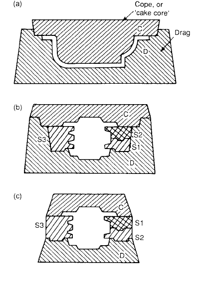
Figure 10.5 (a) Simple cake core and drag assembly;
and (b) a cope and drag with side cores, all located in the
drag; (c) an apparently lower-cost alternative to (b),
but resulting in possible loss of dimensional control.
Rule 10. Provide location points 181
the issues with the casting oriented in one
direction, only to realize that such an orienta-
tion involves insoluble problems. The casting is
then turned upside down and the exercise is
repeated in the hope of a better outcome. Such
experiences are the day to day routine of the
casting engineer.
Furthermore, the complexity of the issues is
not easily solved at this time by computer. There
have been many such attempts, but it is fair to
say at this stage such efforts have not been
developed to such a degree that the professional
casting expert is offered any significant help.
However, of course, we may look forward to the
day when the computer can provide useful
solutions.
10.6 Casting accuracy
There is, of course, very little reason to go to
great lengths regarding the provision of casting
location points if the casting is hopelessly inac-
curate in other ways. This section draws atten-
tion to the general problems associated with
casting accuracy.
Any casting that we make is, in common with
all other manufactured products, never quite
perfect in terms of size and shape. To allow for
this, tolerances are quoted on engineering
drawings. So long as the casting is within tol-
erance, it will be acceptable.
Some reasons for the casting being out of
tolerance include elementary mistakes like the
patternmaker planting the boss in the wrong
place. This leads to an obvious systematic error
in the casting, and is easily recognized and dealt
with by correcting the pattern. It is an example
of those errors that can be put right after the
first sample batch of castings is made and
checked.
Another common systematic error in castings
is the wrong choice of patternmaker's contrac-
tion allowance. The contraction of the casting
during cooling in the mould is often of the order
of 1 or 2 per cent. However, it depends strongly
on the strength of the mould. For instance, in an
extreme case, a perfectly rigid mould will fix the
casting size; in such a situation the casting
simply would have to stretch during cooling
since it would be prevented from taking its
natural course of contracting. To summarize,
the choice of contraction allowance prior to the
making of the first casting is often not easy, and
is often not exactly right. This point is taken up
at length in Castings 2003, with recommenda-
tions on how to live with the problem.
Other errors are less easily dealt with. These
are random errors. No two nominally identical
castings are precisely alike. The same is true for
any product, including precision-machined
parts. The ISO Standard (1984) for casting tol-
erances indicates that although different casting
processes have different capabilities for preci-
sion, in general the inaccuracies of castings grow
with increasing casting size, and the standard
therefore specifies increasing linear tolerances as
linear dimensions increase. (Nevertheless it is
worth pointing out that the corresponding per-
centage tolerance actually falls as casting size
increases.) Other work on the tolerancing of
castings suggests that the ISO standard is still in
its early days, and has considerable potential for
further improvement (Reddy et al. 1988).
Because of the effects of random errors being
superimposed on systematic errors, it is of
course risky to attempt to correct the pattern-
maker's error by moving the boss into an
apparently correct location simply after the
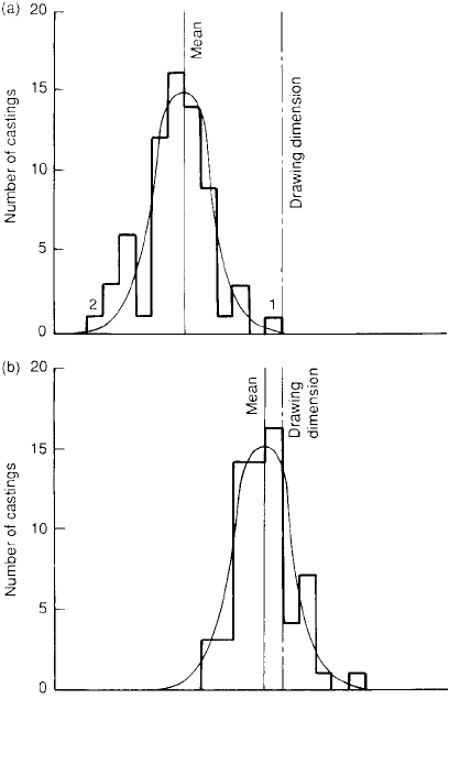
production of the first trial casting. Figure 10.6
illustrates that the random scatter in positions
might mean that the boss appeared to be in the
Figure 10.6 Statistical distribution of casting dimensions
(a) before, and (b) after pattern development. Based
on Osborn (1979).
182 Castings Practice: The 10 Rules of Castings
correct place first time if the casting happened to
be number 1 in Figure 10.6, or might have been
over twice as far out of place, compared to its
average position, if the first casting had been
number 2. A sample of at least two or three
castings is really needed, and preferably ten or a
hundred. The mean boss location and its stan-
dard deviation from the mean position can then
be known and the appropriate actions taken.
At the present time it will be of little surprise to
note that such exemplary action is not common
in the industry. This is because companies are not
generally equipped with a sufficient number of
fast, automated three-coordinate measuring
machines. As such standards of measurement
become more common, so the attainments in
terms of accuracy of castings will increase.
Finally, as we have seen, the ISO Standard
gives the general trend of increase in the size of
random errors as casting size increases. How-
ever, the casting designer and engineer require
much more detailed knowledge of the sources of
individual contributions to the final total error.
The remainder of this chapter is an examination
of these contributions. The reduction of these
errors allows the production of castings that are
considerably more accurate than the minimum
accuracy requirements of the International
Standard Organization document.
10.7 Tooling accuracy
Tooling is taken to include the pattern and its
coreboxes, or the die, and any measuring or
checking jigs and gauges.
The problem of constructing the pattern,
allowing correctly for the contraction and dis-
tortion of the casting, has already been dis-
cussed and will not be dealt with here.
Patterns used in sand casting, and dies used
in die-casting, are subject to wear, so that the
casting gradually becomes oversize. Conversely,
the tooling of many processes is also subject to
build-up problems associated with the deposi-
tion of small amounts of mould aggregate and
binder on the surface of the tooling, and the
gradual accumulation of release agents that may
be used, causing parts of the casting to become
undersize.
Distortion is another problem. Wood is a
useful and pleasant material for pattern con-
struction. It is easily worked, light to handle,
and easily and quickly repaired or modified as
necessary. Even so, it is not a contender for
really accurate work because of its tendency to
warp. A good patternmaker will attempt to
reduce such movement to a minimum by the
careful use of ply and the alignment of the grain
of the wood, together with strengthening bat-
tens. The use of various stabilized woods and
synthetic wood-like materials has also helped
considerably (Barrett 1967). Nevertheless the
ultimate stability in tooling is only achieved with
the use of metal, or cast resin that is properly
supported in metal frames. Cast-resin patterns,
especially when cast into aluminium alloy
frames for strength and rigidity, are usually
extremely reliable. However, some resin systems
such as polyurethanes tend to suffer from the
absorption of solvents from the chemical bin-
ders in the sand, and so suffer swelling and
degradation (Gouwens 1967). Cast-resin pat-
terns that are backed with wood frames are not
reliable; the warpage of the wood distorts the
internal resin shape, usually within a month or so.
After a year the tooling is seriously inaccurate,
so that cores produced from such equipment
will not assemble properly.
The working temperature of tooling affects
the casting size directly; a warm pattern will give
a slightly larger casting. If we consider an epoxy
resin corebox cast into an aluminium alloy
frame, the box will largely take its size from the
temperature of the metal frame (i.e. not the
internal lining of epoxy resin). If the tempera-
ture at the start of the Monday morning shift is
10
C, and if the returning sand creeps up to
30
C by the end of the morning, then for a
500 mm long casting the 20
C temperature rise
will cause the castings to grow by 20 20
10
ÿ6
500 0.2 mm. This is not large in itself,
but when it is added to other random variables
the uncertainty in the final casting length
becomes increasingly out of control.
Anderson (1987) emphasized the important
requirement that for the most accurate work the
pattern or die should be utilized as an adaptive
control element in production. Thus it needs to
be built in such a way that it can be modified to
produce the required size and shape of the
casting. The use of patterns split transversely
across their major length is common. The prior
insertion of a spacer in this split allows the
spacer to be removed and replaced by some-
thing thinner or thicker as necessary. Such
simple techniques involve only modest extra
expense during the construction of the pattern
but are a reassurance against the possibility of
major expensive rebuilds later.
10.8 Mould accuracy
Mould accuracy depends strongly on the mould
assembly method. Usually, a mould assembly
simply involves two parts; a cope and a drag.
This makes for maximum accuracy. On other
Rule 10. Provide location points 183
occasions the mould assembly can be compli-
cated, requiring many parts, and requiring
much discussion between the pattern shop,
foundry, and casting designer to find an
appropriate solution. Accuracy can now
become illusive and troublesome.
As a general rule, it is useful to ensure that
even in the most complicated of mould assem-
blies, the design of the assembly consists prin-
cipally of a drag and a cope. In addition, all
parts should be interrelated via a single mould
part, which will normally be the drag. In this
case the assembly of cores will be in the drag,
with each core located separately to prints in the
drag, and the final operation will simply consist
of closing with the cope. The cope also should
have features that contact and locate directly on
the drag as the key mould part.
Such simple rules are easily forgotten. One
can see many ambitious castings that have failed
to achieve dimensional acceptability because the
mould assembly has resembled a random heap
of assorted blocks: one layer of cores tottering
upon another, with finally the cope perched
precariously on top. Clearly, the details of the
casting formed in the cope bear no constant
relation to the details formed in the drag.
The simplest form of construction of moulds
that was widely popular consisted of a drag with a
cope in the form of a `cake core' as shown in
Figure 10.5a. Accuracy was excellent. However,
this simple construction did not allow for the
placement of any useful bottom-gated running
system, and the top pouring that had to be
accepted as a consequence might have been mar-
ginally acceptable for some rough and ready grey
iron castings in greensand moulds but did not give
good results for the majority of casting alloys.
Figure 10.5b shows a simple type of cope±
drag arrangement with side cores, all located in
the drag, apart from side core S2, which rests on
S1. It was judged that the small accumulation of
errors in the positioning of S2 would be accept-
able in this case. If the positioning of S2 had
been critical, it could still have been located in
the drag by stepping the contour of the drag
appropriately to form a convenient location.
Figure 10.5c shows how it would have been
easy to have saved some sand by abandoning
the deep drag construction, and having a core
assembly that consisted simply of a pile of cores,
rather than a proper cope and drag. The overall
accuracy of the casting now suffers from the
accumulation of errors introduced by the inter-
mediate side cores S1, S2 and S3. There will, for
instance, be a poor match between the top and
bottom features of the casting.
The dimensional problems that arise in set-
ting cores are examined by Skarbinski (1971). In
general it needs to be said about the accurate
printing of cores that the core print should be
designed assuming that the core will be pro-
duced with errors in its size and shape, and will
have to fit into a mould which will also have
suffered some distortion during its manufacture.
The print also sometimes has to restrict the
movement of the core during mould filling
because of buoyancy, and yet may also have to
allow the relative movement of the core in its
print to permit the thermal expansion of the
core. All this is a seemingly impossible task to
achieve accurately. However, it is usually solv-
able by applying the following simple rules:
1. The print requires tolerance where it needs to
fit (i.e. must not be made size-for-size, that
would have produced an interference fit. The
only exception to this is the heights of cores
where cores are stacked one on top of the
other, since in this case the accumulation of
errors requires to be kept to a minimum).
2. The print requires clearance where it is not
required to fit, and where expansion clear-
ance is required.
Rules often appear pedantic or even pedes-
trian when they are spelled out! However, the
application of the rules involves much work that
is seldom expended on the design of pattern-
work. Although some prints are easily and
quickly designed, others require lengthy agon-
ized consideration resulting in compromises that
have to be carefully assessed. Every print
requires such detailed design. It is attention
to details such as these that makes the difference
between the inadequate and the excellent
casting.
Nevertheless, these problems are eliminated if
the use of the core can be avoided altogether.
(The situation is reminiscent of Feeding Rule 1:
Avoid using a feeder if possible. The useful
equivalent rule for cores, that makes an addi-
tional rule for mould assembly, is:
3. The number of cores should be reduced to a
minimum, moulding as much as possible
directly in the cope and drag.
Not only does the application of this principle
reduce dimensional errors, but also the addition
of each core involves considerable extra tooling
cost, and an additional cost in the production of
the casting, sometimes approaching the cost
of the production of a cope or drag. The addi-
tion of a core between a cope and drag repre-
sents the third piece of sand to be added to the
two original mould halves; thus the costs at this
stage may increase by 50 per cent for the
addition of the first core. At other times a small
184 Castings Practice: The 10 Rules of Castings
core can save money by avoiding extra com-
plexity of the tooling. Each case needs separate
evaluation.
A high hidden addition to total casting costs
results from the use of cores. These difficult to
assess costs arise from the accumulation of a
number of minor operations, most of which are
usually overlooked. For instance, the core needs
to be scheduled, made (perhaps on a capital-
intensive core-blowing machine), deflashed,
stored on special racks (taking up valuable floor
space), retrieved from storage, transported to
the moulding line, and then correctly assembled
into the mould. Errors arise as a result of the
incorrect core being made or transferred, or
sufficient are broken in storage or transit to
cause the whole process to be repeated. Alter-
natively, its assembly into the mould gets for-
gotten at the last moment! Cores are therefore
almost certainly more expensive than most
foundry accounting systems are aware of. (The
costs of chills, and of scrapped castings, are
similarly illusive and not widely understood.)
A further use of cores, in addition to their
obvious purpose in providing detail that cannot
be moulded directly, is that the running system
can often be integrated behind and underneath
them, the main runner and gates being located
beneath a base, side or end core. This is a
valuable facility offered by the use of a core and
should not be overlooked. In a number of
castings the addition of a core may be for the
sole purpose of providing a good running sys-
tem. Such a core is often money well spent!
The problem with the automation of core-
assembly systems is finding the core again after
it has been put down on, for instance, a con-
veyor or a storage rack. This is a difficult job for
a robot, since extreme accuracy is required, and
the cores are often of extreme delicacy. Clearly,
one method of solving this problem is never to
put the cores down in the first instance.
Schilling (1987) succeeded in developing this
concept with a unique system of making and
assembling cores in which the cores are not
released from one half of the opened corebox
until the other half of the core has already been
located in the core-assembly package. In this
way the cores are assembled completely auto-
matically and with unbelievable precision. Cores
are located to better than 0.03 mm, allowing
them to be assembled with clearances which are
so small that the cores could not be assembled
by hand. In fact the cores are sprung into place
with interference fits. The rigorous application
of this technique means that castings need to be
designed for the process, since the assembly
of each core is by vertical placement over the
previous core. For instance, any threading of
cores in through holes in the sides of other cores,
such as often occurs with port cores through the
water jacket core of a cylinder head casting, is
not possible. This disadvantage will limit the
technique to partial application, loading some
but not all cores of a cylinder head, for instance.
Even this would be an important advance.
A final note in this section relates to cope-to-
drag location. This is, of course, of primary
importance. Failure to achieve good location
results in a mis-match defect. Mis-match is a
lateral location error, and not to be confused
with the vertical precision with which cope and
drag meet, which is normally of the order of
0.05 to 0.10 mm.
In foundries using moulds contained in
moulding boxes, however, mis-match is unfor-
tunately all too common and is usually the result
of the use of worn pins and bushes that are used
to locate the boxes. Southam (1987) analyses the
effect of the errors involved in the pin and bush
location system. These are numerous and ser-
ious. The pin-to-bush clearance is typically
0.25 mm, and given an apparently acceptable
additional wear of 0.35 mm, he finds that the
total possible mis-match between cope and drag
moulds is as much as 1.5 mm.
He proposes, therefore, a completely differ-
ent system, in which pins and bushes are elimin-
ated. The cope and drag boxes are simply
guided by wear blocks fixed to the outside edges
of the box. These slide against two guides on the
long side of the box, and one guide against the
narrow side of the box during moulding and
closing operations. The boxes are held against
the guides by light spring pressure, or by pneu-
matic cylinders. The system appears deceptively
simple, but actually requires a certain amount of
good engineering to ensure that it operates
correctly on mould closure, as Southam
describes. Although Southam calls his method
the three-point registration system, it is in reality
a classical six-point location system, since he
uses a further three points to locate the drag in a
parallel plane to the cope during closure.
The ability to locate cope to drag with neg-
ligible error has a number of benefits that
Southam lists. The maintenance and replace-
ment of worn pins and bushings is a foundry
chore and expense that is eliminated. (In fact
anyone who has not experienced the problem of
carrying out such an operation in a jobbing
foundry will have a problem to comprehend the
awesome scale of the task, because of the hun-
dreds of pins and bushes, and the relentless wear
problem, requiring the operation to be repeated
at regular intervals despite the multitude of
pressing problems elsewhere in the foundry
environment.) Instead, only three guides on the
Rule 10. Provide location points 185

closer and three each on the cope and drag
pattern need to be checked, and the effect of
wear of these parts on mis-match is minimal
because the resultant displacement is largely
self-compensating.
For the case of precision core packages, the
sand mould is not contained in a box, and thus has
to belocated directly witha sand-to-sandlocation.
Since this is defined from the patternwork, the
location relates perfectly to the casting details, and
mismatch is therefore not possible.
10.9 Summary of factors affecting
accuracy
Some of the many factors that control the
accuracy of the final casting have been dealt
with above, and some are planned for inclusion
in Castings processes to follow this publication.
We shall therefore content ourselves here with a
brief summary:
1. Pattern inaccuracy.
2. Mould inaccuracy.
3. Mould expansion and/or contraction because
of temperature and pressure.
4. Casting expansion because of precipitation of
less dense phases such as graphite or gases.
5. Casting contraction on freezing causing local
sinks.
6. Casting contraction on cooling leading to
(a) different overall casting size, depending
on the constraint by the mould, and (b)
distortion if unevenly constrained or un-
evenly cooled.
7. Casting overall change of size on heat treat-
ment or on slow ageing at room temperature.
8. Casting distortion if unevenly cooled by an
inappropriate quenchant or too rapid quench
from heat-treatment temperature.
9. Casting distortion caused by shot blasting.
This effect has not been dealt with previously.
The compressive stresses introduced into the
surface by a peening effect can lead to the
distortion of the casting as reported by Kasch
and Mikelonis (1969). The effect is widely
used in the sheet metal industry to induce the
controlled forming of curved surfaces; air-
craft wing panels are formed from flat sheets
in this way; the flat product gradually curves
away, becoming convex towards the direc-
tion of the impingement of the shot. Con-
trolled shot peening is also used to increase
the fatigue resistance of castings as discussed
by Lawrence (1990) and O'Hara (1990).
10.10 Metrology
Even if it were possible to produce an absolutely
accurate casting, it would not be possible to
prove it! This apparently curious statement is
the consequence of errors that occur during
measurement. Inexact measuring of the casting
will cause apparent random deviations in the
dimensions of the casting. Svensson and Villner
(1974) point out this problem, and work out
the influence of measuring accuracy on the
apparent dimensional accuracy of the casting.
Table 10.1 is based on their work.
It is clear that even if the casting has dimensions
that are quite correct, even careful measurement
will introduce a certain amount of apparent error,
and careless measurement will, ofcourse, introduce
even more. These errors have been a traditional
problem within the industrybut theintroduction of
large-size three-dimensional coordinate measuring
machines has significantly helped.
Even so, problems still remain. For instance,
Swedish workers point out that for small dimen-
sions, and where high accuracy is required, the
surface roughness will influence the apparent
accuracy of the casting. Thus a change in the
surface finish from 75 mm to 200 mm will give an
increase of one tolerance grade in the ISO system.
Table 10.1 Limits of accuracy of measurements
Measuring equipment
and range
(mm)
Accuracy of
measurement
(mm)
Mean dimension
(mm)
Accuracy
(%)
ISO tolerance
grade IT
Steel tape >1000 1 1000 0.10 13
2000 0.05 12
5000 0.02 11
Steel rule 500±1000 0.5 500 0.10 12
1000 0.05 11
Vernier calliper 0±500 0.1 50 0.20 10
100 0.10 10
200 0.05 9
500 0.02 9
186 Castings Practice: The 10 Rules of Castings
The surface finish influences the measurement
and location processes in other ways. For instance,
the modern touch probes, which locate dimensions
on the casting with the most delicate of contact
pressure, effectively only measure to high spots,
thus biasing the measurements in one direction:
exterior dimensions on the casting are measured
oversize, and cored holes appear undersize.
Results from mark-out equipment using a
scribing line tend to give more averaged results,
since minor surface irregularities are cut through.
Similarly, when castings are clamped on to
their location points, the small area of the contact
points, typically 5 mm diameter, and the high
loads which can be exerted by the clamps, ensure
that the locating jig point actually indents the
surface of the casting by up to 0.25 mm for some
aluminium alloy sand castings. Harder materials
such as cast irons will, of course, indent less. All
surface irregularities are effectively locally
smoothed and averaged in this operation. The
indentation effect sets an upper limit to the
accuracy and repeatability with which castings
can be picked up for measurement or machining.
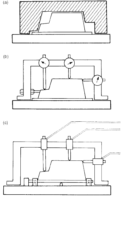
A traditional method of checking the profile of
a casting is by the use of template gauges. These
are typically sheets of metal that have been cut to
the correct contour. On applying them to the
casting, the contour on the casting can be seen to
be correct or not, depending on the clearance that
can be seen between the two. This is an analogue
technique that can no longer be recommended in
these modern times. The gauges are expensive to
make. They are also subject to wear, and thus need
to be checked regularly and occasionally replaced.
However, what is much more serious, they are
difficult to use in any effective way. This is because
in practice the contours never match exactly. The
problem for the user then is how inaccurate can
the contour of the casting be allowed to become
before remedial action must be taken?
Theuse of`go/no-go' gaugesremovesthematter
of judgement. However, the gauges are again
subject to wear, and thus require the cost
and complexity of a calibration system. More
fundamentally, their use is similarly not helpful in
terms of providing useful data to assist process
control.
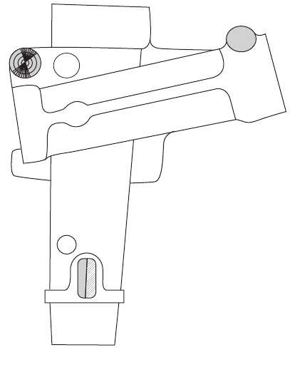
All these difficulties can be removed by the use
of a much simpler technique: the use of simple
goalpost fixtures that straddle the casting and are
equipped with one or more spring-contact probes,
such as dial gauges. The readings from the gauges
are read and recorded. The operation becomes
even simpler with the use of digital read-out
devices (Figure 10.7). Linear transducers are
easily fitted and operated, and give an immediate
numerical signal of the degree of inaccuracy.
The goalpost would be calibrated and stored
on a standard casting, and thereby always be seen
to be in calibration by being set to zero in this
position. (For calibration away from the zero,
other readings can be obtained by the insertion of
slip gauges under the probe.)
The use of digital electronic read-out in this
way allows its incorporation into data-logging
and quality-monitoring systems, such as statis-
tical process control. By watching the trends on
a daily or weekly basis, the gradual drifts in
casting dimensions can be used to predict, for
instance, that tooling wear will reach a level that
will require the tooling to be replaced in three
weeks' time. Such prior warning allows the
appropriate action to be planned well in
advance.
Figure 10.7 Comparison of checking techniques for the
monitoring of the size and shape of castings by:
(a) template, with the casting and template sat on a
baseplate; (b) an equivalent analogue measurement using
spring dial gauges; and (c) digital measurement using
linear displacement transducers, with the casting located
on a six-point jig. The six-point locations for the goalpost
frame on the jig are omitted for clarity.
Rule 10. Provide location points 187