John Campbell. Castings Practice:The Ten Rules of Castings.2004
Подождите немного. Документ загружается.

the quenchant can easily reach all parts, are
often not seriously affected, because DT is
necessarily small.
The actual magnitude of the strain e is salu-
tary to estimate. For aluminium a is about
20 10
ÿ6
K
ÿ1
and the temperature fall during a
quench is approximately 500 K. The strain
works out to be therefore approximately 1 per
cent. For steels a is approximately 14 10
ÿ6
,
and the temperature change for quench from
many heat treatments in the region of 900 K,
again giving a strain close to 1 per cent. Since
the yield (or proof ) strain is only approximately
0.1 per cent, these imposed quench strains are
about ten times the yield strain, and can there-
fore be seen to take the component well into the
plastic deformation range.
Parts that are particularly susceptible include
large, thick section castings, where the heat of
the interior takes time to reach the outside of the
casting, giving high DT. Ingots or other block-
type products can be seriously stressed for this
reason. Direct chill (continuously cast) ingots
aluminium alloys are severely cooled by water,
but are often over 300 mm diameter. While sit-
ting on the shop floor awaiting further proces-
sing the strong 7000 series alloy ingots have
sometimes been seen to explode like bombs. (As
an aside, the length of time taken before the
ingot decides to fail is curious and interesting.
It seems likely that the failure under the high
internal stresses is initiated from one of the large
bifilms that is expected to be entrained during
the turbulent start of casting. The gradual pre-
cipitation of hydrogen into the bifilm will gra-
dually increase the pressure in the bifilm crack,
encouraging it to extend as a stress crack. The
hydrogen may be already in solution in the
metal, or may be gradually accrued by reaction
with water vapour in the atmosphere during
storage, especially if the bifilm is connected to
the exterior of the ingot surface, allowing direct
penetration of water vapour. Other penetrating
contaminants may include air to cause addi-
tional internal oxidation, or fluxes, or traces of
chlorine gas, or sulphides from greases, to act as
surface active additions to reduce the surface
energy of the metal and so further encourage
crack growth. Research to clarify these possi-
bilities would be valuable.)
Other varieties of castings that are suscep-
tible to damaging levels of residual stress include
those that are hollow, with limited access for the
quenchant into the interior parts of the casting,
and which also have interior geometrical fea-
tures such as dividing walls and strengthening
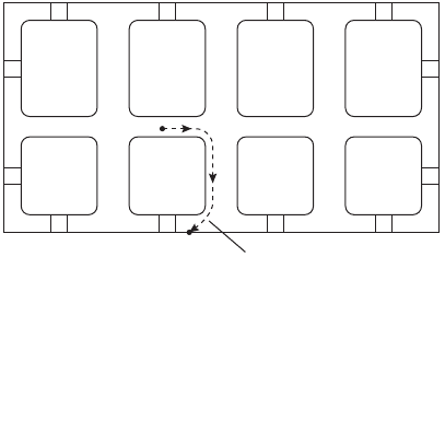
ribs (Figure 9.1). This latter series of geometrical
requirements might seem to eliminate most
castings. Perhaps surprisingly therefore, the list
of castings that fulfils these requirements is
rather long, and includes such excellent exam-
ples as automotive cylinder heads and blocks,
and housings for components such as com-
pressors and pumps. When immersed in the
water quench, the water attempts to penetrate
the entrances into the hollow interior of the
casting. However, because the casting is origin-
ally above 500
C, any water that succeeds in
entering will convert almost instantaneously to
steam, blowing out any additional water that is
attempting to enter. The result is that the out-
side of the casting cools rapidly, whereas the
interior can cool only at the rate that thermal
conduction will conduct the heat along the tor-
tuous path via interior walls of the casting to the
outer surfaces.
The rate of conduction of heat from the
interior to the exterior of the casting can be
estimated from the order of magnitude relation
x Dt
1=2
(9.2)
where x is the average diffusion distance, D is
the thermal diffusivity of the alloy, and t is the
time taken. The thermal diffusivity is defined as
D K=rC (9.3)
where K is the thermal conductivity, about
200 W m
ÿ1
K
ÿ1
for aluminium, the density r is
about 2700 kg m
ÿ3
and the specific heat C is
approximately 1000 J kg
ÿ1
K
ÿ1
. These values
yield a value for the thermal diffusivity D close
to 10
ÿ4
m
2
s
ÿ1
. (The corresponding value for
steel is approximately 10
ÿ5
m
2
s
ÿ1
.) Equation 9.1
is used to generate Figure 9.2 in which the
Typical ~100mm path for
diffusion of heat from the
centre of the casting during
a quench
Figure 9.1 Schematic representation of a hollow casting
with small ports to the outside world and internal walls,
such as a cylinder head, illustrating the long diffusion path
for heat during a quench, together with the high internal
tensile stress that might result in failure.
168 Castings Practice: The 10 Rules of Castings
distance for diffusion of heat out of a product
indicates the approximate boundaries of safe
regimes constituting conditions in which suffi-
cient time is available for the diffusion of heat
from the interior during the quench. The time of
cooling in different quenchants over the critical
range of approximately 500
C down to 250
C
is provided by results such as that shown in
Figure 9.3. These results were obtained by siting
a thermocouple in the centre of a 10 mm wall of
an Al±7Si±0.4Mg alloy casting. Similar results
would be valuable for ferrous materials.
For a solid aluminium bar of 20 mm dia-
meter, or a solid plate of 10 mm thickness,
Figure 9.3 indicates that quenching in water will
reduce the temperature from 500 to 250
C in
about 5 seconds. Substituting 5 s in Equation 9.2
shows that on average heat will have travelled
20 mm in this time. The 20 mm bar or 10 mm
plate will both therefore enjoy a reasonably
uniform temperature so that minimal stress will
be generated.
If, when quenching castings following high
temperature heat treatment, the time for cooling
the outer sections of castings is shorter than the
time required for heat to diffuse out from
interior sections, the outer parts of the casting
cool to form a rigid frame. However, the inner
sections will cool and contract later, but by that
time unfortunately experiencing the restraint of
the outside rigid sections. Thus the interior
sections go into tension, and the outer parts into
compression.
As stated above, this situation is common in
such castings as automotive cylinder heads,
whose links between the internal sections and
the outside world are via tortuous routes around
the water jackets. The total distance that heat
now has to diffuse is of the order of 100 mm.
However, the walls of the casting are 10 mm or
less, so that the cooling of the exterior of the
casting will again occur in a time of the order of
5 seconds. However, Figure 9.3 indicates that
approximately 100 seconds is required for the
heat to diffuse the 100 mm distance from the
inside to the outside, so the interior of the cast-
ing will be expected to experience high tensile
stress.
If the cylinder head casting had been sub-
jected to quenching in a blast of air, Figure 9.3
indicates that cooling will now take a leisurely
100 seconds or so. Thus sufficient time is
available for the internal sections to lose their
heat to the outside so that the casting maintains
a reasonably uniform temperature during the
quench. The generation of high internal stress is
avoided.
The author has personal experience of
quenching complex cylinder heads into water,
and has suffered the consequences of banana-
shaped castings that required to be straightened
with a 50 000 kg press specially bought-in to
rectify the damage. Those were the castings that
did not crack in the quench itself (the internal
cracks inside the water jackets were often diffi-
cult to locate). In addition, castings failed by
fatigue in service after only short lives. The
introduction of polymer quenching eliminated
the problem. As explained in Castings (2003)
there are a number of polymers that can be used.
One commonly in use is a solution of polyalk-
ylene glycol in water. The polymer precipitates
out of solution at 73
C, and so deposits over the
surface of the hot castings, forming a sticky,
viscous layer. The layer is resistant to boiling, so
that a vapour blanket is avoided, and a steady,
uniform flow of heat from the casting into the
water is achieved. When the casting finally
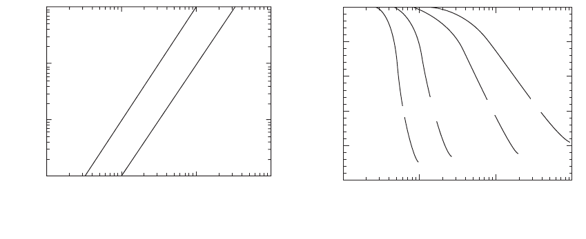
Figure 9.3 Quench rates in a 10 mm thick Al plate casting
in a variety of quench media.
Rule 9. Take action to reduce residual stress 169
Time taken for exterior of casting to cool
through the critical temperature range (s)
1 10 100 1000
Average distance for diffusion of heat during quench (mm)
Low
stress
Danger
of
high stress
Threshold for steel
Threshold for Al alloys
1000
100
10
1
Figure 9.2 Regime of low stress in terms of quench rate
and distance for heat flow.
500
400
300
200
100
0
1 10 100 1000
Time (s)
Temperature (°C)
Water
30%
polymer
Forced
air
Still
air
cools below 73
C the polymer goes back into
solution.
However, the polymer quench was not a
long-term practical solution for production for
an automotive product. It had to be cleaned
out of internal cavities where it could lodge,
becoming concentrated and carbonized during
the subsequent ageing treatment. In addition,
any residual core sand in such locations would
be effectively cemented into place to cause
damage later in the life of the engine when it
finally became dislodged.
In contrast to its use with automotive cast-
ings, polymer was excellent for aerospace cast-
ings where the extra trouble to clean each
casting individually did not outweigh the benefit
of superb heat treatment response and reduced
internal stress.
Air quenching was, however, a complete
solution for automotive castings. It was low cost
and quickly and easily implemented in a series
production environment. The castings retained
their accuracy, and quench failures and fatigue
failures disappeared. We were able to restore
productivity and profitability (and get our
money back for the press).
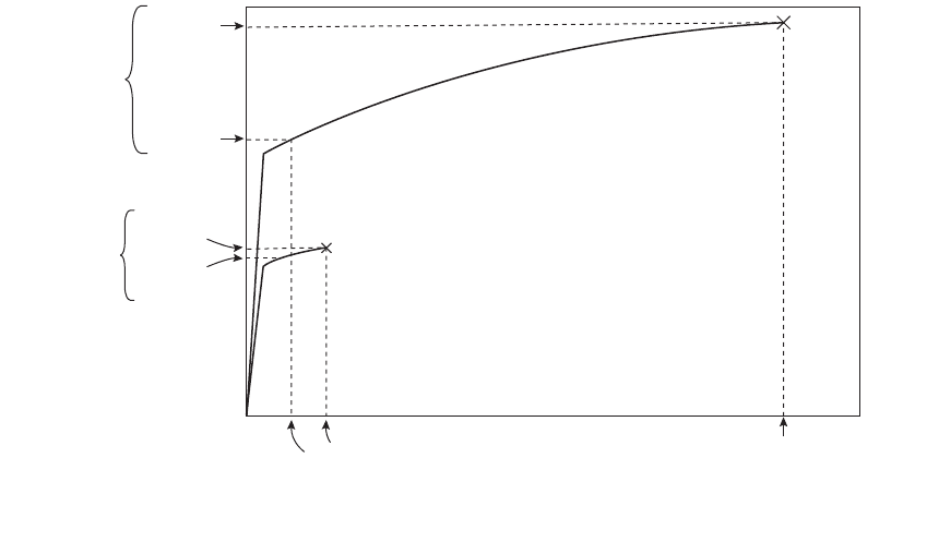
Figure 9.4 illustrates how the overall strength
of a casting can be reduced by a heat treatment
designed to increase the strength of its material.
Figure (a) shows the stress±strain curve for the
alloy, and the imposition of 1 per cent; tensile
strain on the inner parts of the casting as a result
of a water quench. This quench strain results in
a quench stress close to the failure stress of the
material. If no ageing treatment is carried out
this stress is locked into the component for the
rest of its life. Naturally, it has little residual
strength left, and is likely to fail on the first
application of a stress in service.
However, after an ageing treatment in which
the yield strength of the alloy was intended to be
doubled, the situation is shown in Figure 9.4(b).
Assuming the benefit of a small amount of stress
relief (the amount indicated in the figure may be
rather generous), the residual quench stress is
only slightly lower; substantially unchanged. If
additional service stress in tension is applied to
the central parts of the casting, the residual
tensile stress in these parts is effectively a starting
point for the additional loading. Thus, effec-
tively, the new stress±strain curve for the com-
ponent is shown in (c). It is clear that the new
overall stress±strain response has been reduced
compared to the original unheat-treated mate-
rial; as a result of our lengthy, complex and
expensive heat treatment the component is
effectively weakened.
In summary, the residual stress in aluminium
alloy castings quenched into water in this way is
well above the yield point of the alloy. Even
after the strengthening during the ageing treat-
ment, the stress remains at between 30 and 70 per
cent of the yield stress, with a useful working
approximation being 50 per cent. Thus the
useful strength of the alloy is reduced from its
unstressed state of 100 per cent, down to around
50 per cent. This massive loss of effective
strength makes it inevitable that residual tensile
Failure
stress
Quench
stress
0.1%
proof
stress
0.1%
proof
strain
1%
applied
strain
0.1% Strain
e
0.1PS
(a) (b) (c)
0.1PS
Stress, r
Minimal stress
relief during
ageing treatment
Residual
stress
New effective
baseline
Figure 9.4 Evolution of the stress/strain curve of an Al alloys as heat treatment progresses (a) after quench; (b) after
ageing to double the 0.1 per cent proof stress; and (c) the final effective stress/strain curve showing properties
effectively less than the as quenched properties.
170 Castings Practice: The 10 Rules of Castings
stresses are a significant cause of casting failure
in service, particularly fatigue failure, since the
residual stress is always generously above the
fatigue limit of the alloy.
For many castings, the use of a boiling water
quench has been demonstrated to be of negli-
gible help in reducing the stresses introduced by
water quenching (Castings 1991). Thus although
the rate of quench is certainly reduced by the
use of hot or boiling water the results are not
always reliable. This is almost certainly the
consequence of the variability of the vapour
blanket that forms around the hot casting.
The blanket forms and disappears irregularly,
depending on many factors including the precise
geometry of the part, its inclination during the
quench, and the proximity of other hot castings,
etc. In addition, from a practical point of view, a
hot water quench is not cheap to install, run or
maintain.
Turning now to steels; in contrast to the
behaviour of Al alloys, the thermal diffusivity
D is approximately ten times lower, of the order
of only 10
ÿ5
. The reader can quickly show that
the corresponding distances to which heat can
flow are 7 mm in 5 seconds but only 30 mm in
100 seconds. For a given rate of quench there-
fore, steels will suffer a higher residual stress
(Figure 9.2). Nevertheless, they are much more
able to withstand such disadvantages, having
higher strength, but more particularly, higher
elongation. Thus although the final internal
stress is high, the steel product is nowhere near
the failure condition experienced by the alumi-
nium alloy casting. The aluminium alloy casting
experiences about 1 per cent imposed elongation
but has only a few per cent, perhaps even less
than 1 per cent elongation prior to failure. Thus
it can fail actually in the quench, or early in
service. In contrast, the steel casting has ten or
twenty times greater elongation (as a result pri-
marily of its reduced bifilm content). Thus
although the 1 per cent or so of imposed quench
strain resulting from unequal cooling may result
in 1 per cent or so of distortion of the product,
its condition is far from any dangerous condi-
tion that might result in complete failure, since
enormously greater strain has to be imposed to
reach the failure condition (Figure 9.5).
The above statements are so important they
are worth repeating in different words for
additional clarity. The rapid quenching of steels
for metallurgical purposes (such as the stabili-
zation of austenite for Hadfield Manganese
steel) is not usually a problem. The reason is
that most steels are particularly clean, because
of the rapidity with which entrainment defects
are deactivated and/or detrained after pouring.
The result is that steels typically have an elon-
gation to failure of 40 or 50 per cent. In contrast,
most Al alloys (and probably most Mg alloys)
do not enjoy this benefit; suffering from a high
Figure 9.5 A comparison of stress/strain curves of an Al alloy and a steel, illustrating the relatively dangerous
condition of the Al alloy after a quench.
Rule 9. Take action to reduce residual stress 171
Ultimate
stress
Quench
stress
Quench
stress
Ultimate
stress
Approx 1%
quench strain
Failure strain
for steel
Failure strain for Al alloy
Steel
Al alloy
density of bifilms they typically achieve less than
a tenth of this ductility. Thus the application of
1 per cent strain takes the aluminium alloy close
to, or even sometimes in excess of its failure
strain. For steels, even though the 1 per cent
strain applied by the quench will take the part
into the plastic region, causing huge stresses, the
steel remains safe; its greater freedom from
bifilms permits it to endure enormously greater
extension before it will fail (Figure 9.5).
For the future, the production of Al alloys
with low bifilm concentration promises to offer
ductilities in the range of that of steels. Already,
good foundries know that high strengths to-
gether with elongations of 10 to 20 per cent are
achievable, if good care is taken.
Slower quenching techniques are safer, al-
though, of course, the strength attained by the
heat treatment is somewhat reduced. Even so,
the reduced mechanical strength when using
slower and more controlled quenches such as a
polymer or a forced air quench is more than
compensated by the benefit of increased relia-
bility from putting unstressed (or more accu-
rately, low-stressed) castings into service. Thus
the casting designer and/or customer needs to
specify somewhat reduced mechanical strength
and hardness requirements in order to gain a
superior performance from the product. The
reductions of strength and hardness are expected
to be in the range 5 to 10 per cent, but the
improvement in casting performance can be
expected to be approximately 100 per cent. These
are huge benefits to be gained at no extra cost.
9.4 Distortion
Residual stresses in castings are not only serious
for parts that require to withstand stress in
service. They are also of considerable incon-
venience for parts that are required to retain a
high degree of dimensional stability. This pro-
blem was understood many years ago, being
first described as early as 1914 in a model
capable of quantitative development by Heyn.
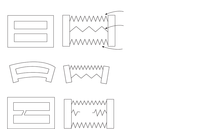
The model of a three-bar casting is shown in
Figure 9.6. The internal stresses are represented
by two outer springs in compression, each car-
rying half of the total load of internal com-
pressive stress, and an inner spring in tension
carrying all of the internal tensile stress. If one
of the surfaces of the casting is machined away,
one of the external stresses is removed. It is
predictable therefore that the casting will deform
to give a concave curvature on the machined side
as illustrated in the figure.
The distortion of castings both before and
after machining is a common fault, and typical
of castings that have suffered a water quench.
Elastic model representing the
equilibrium state of stress
Compression
Compression
Ten sion
Casting
After machining away one part of cast surface
Relief of internal tension by internal fracture
(a)
(b)
(c)
=
=
=
Figure 9.6 Heyn's (1914) model
of the balance of internal stresses
after rapid cooling: (a) the
quenched casting showing high
internal tensile stress and
relatively low external compressive
stress; (b) the distortion of the
casting after one side is machined
away; and (c) the condition of
internal tensile failure.
172 Castings Practice: The 10 Rules of Castings
Once again, it is a problem so frequently
encountered that I have, I regret, wearied of
answering the telephone to these enquiries too.
After all, it is difficult to understand how a
casting could avoid distortion if parts of it are
stressed up to or above its yield point.
For light alloy castings in particular a more
gentle quench, avoiding water (either hot or
cold), and choosing polymer or air will usually
solve the problem instantly. As mentioned
briefly above, such polymer performs well
for aerospace castings but is expensive and
messy, whereas air is recommended as being
clean, economical and practical for high volume
automotive work. Otherwise, stress relieving
castings by heat treatment prior to machining
is strongly recommended (Castings 2003). In
either case, of course, some fraction of the
apparent strength of the product has to be
sacrificed.
9.5 Heat treatment developments
Although not strictly relevant to the question of
reducing residual stresses, it is worth empha-
sizing the newer developments in heat treat-
ments that give approximately 90 per cent or
more of total attainable strength, but with much
reduced stress and greatly reduced cost. The
reduced cost is always an attention-grabbing
topic, and materially helps the introduction of
technology that can deliver an improved product.
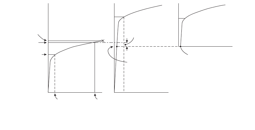
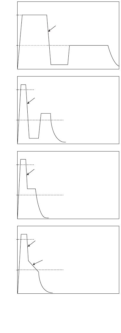
Figure 9.7 illustrates the progression of
recent developments in heat treatment of Al
alloys where the problem of stress is central.
The traditional full heat treatment of a
precipitation-hardened alloy, that constitute the
bulk of cast structural components at this time,
consists of a solution treatment, water quench
and age as illustrated in (a). The treatment
results in excellent apparent strength for the
material, but is energy intensive in view of the
long total times.
Illustration (b) shows how the traditional
treatment can be reduced significantly in mod-
ern furnaces that enjoy accurate control over
temperature, thereby reducing the risk of over-
heating the charge because of random thermal
excursions. An increase in temperature by 10
C
will allow, to a close approximation, an increase
in the rate of treatment by a factor of 2. Thus
times at temperature can be halved. These ben-
efits are cumulative, such that a rise of 20
C will
allow a reduction in time by a factor of
2 2 4, or a rise of 30
C a reduction in time of
a factor 2 2 2 8, etc. Both (a) and (b)
require separate furnaces for solution and age-
ing treatments (if long delays waiting for the
T(°C)
500
200
500
200
500
200
500
(d)
(c)
(b)
(a)
200
Solution
Water or polymer
quench
Water or polymer
quench
Age
Air quench
Air quench
Cool in still air
Figure 9.7 A progression of precipitation heat treatment
developments for Al alloys. (a) A traditional full
treatment, giving excellent apparent properties but
taking between 12 and 24 hours; (b) shortened treatment
giving nearly equivalent result; (c) the use of air quench
to reduce time, energy, and residual stress; (d) an ultimate
short and simple cycle.
Rule 9. Take action to reduce residual stress 173
solution furnace to cool to the ageing tempera-
ture are to be avoided). Thus floor space
requirement is high. Floor space requirement is
increased further by the quench station, and, if a
polymer quench is used, by a rinsing tank
station.
The reader will appreciate that the tiny
additional energy required by the higher tem-
perature is of course completely swallowed by
the huge savings in overall time at temperature.
If an air quench is used to gain the benefits of
reduced residual stress, the additional benefits
to the overall cycle time are seen in Figure (9.7c)
because the quench can now be interrupted and
the product transferred to the ageing furnace
already at the correct temperature for ageing,
saving time and reheat energy. Additional ben-
efits include the fact that the air quench is
environmentally friendly; the castings are not
stained by the less-than-clean water; the con-
veyor is straightforward to build and maintain;
there is no mechanism required for lowering
into water that normally results in complex and
rusting plant. As we have repeatedly empha-
sized, the products from this type of furnace
have somewhat lower apparent strengths and
hardness, but greatly improved performance in
service.
Figure 9.7d shows an ultimate system that
might be acceptable for some products. The
ageing treatment is simply carried out by inter-
rupting the air quench slightly above the normal
ageing temperature, and allowing the part to
cool in air (prior to final rapid cooling by fans if
necessary). This represents a kind of natural
ageing process in which no ageing furnace is
required. Strengths will suffer somewhat, but
the lower costs and simplicity of the process may
be attractive, making the process suitable for
some applications.
9.6 Epilogue
Although the strength of the material will be
lowered by a slower quench, the strength of
the component (i.e. the failure resistance of the
complete casting acting as a load bearing part)
in service will be increased.
If water quench is avoided with a view to
avoiding the dangers of internal residual stress,
it is common for the customer to complain
about the 5 per cent or so loss of apparent
properties. In answer to such understandable
questions, an appropriate reply to focus atten-
tion on the real issue might be `Mr Customer,
with respect, do you wish to lose 5 per cent or
50 per cent of your properties?'
In the experience of the author, a number
of examples of castings that have been slowly
quenched, losing 5 or 10 per cent of their
strength, are demonstrated to double their per-
formance in service (Castings 2003).
Finally therefore, it remains deeply regrett-
able, actually a scandal, that many national
standards for heat treatment continue to specify
water quenching. This disgraceful situation
requires to be remedied. In the meantime the
author deeply regrets having to recommend that
such national standards be set aside. It is easy
for the casting supplier to take refuge in the fact
that our international and national standards
on heat treatment often demand quenching into
water, and thereby avoid the issue that such a
production practice is risky for many compo-
nents, and in any case provides the user with a
casting of inferior performance. However, the
ethics of the situation are clear. We are not
doing our duty as responsible engineers and as
members of society if we continue to ignore
these crucial questions. We threaten the per-
formance of the whole component merely to
fulfil a piece of metallurgical technology that
from the first has been woefully misguided.
The fact is that our inappropriate heat
treatments have been costly to carry out, and
have resulted in costly failures. It has to be
admitted that this has been nothing short of a
catastrophe for the engineering world for the
past half century, and particularly for the
reputation of light alloy castings, not to mention
the misfortune of users. As a result of the
unsuspected presence of bifilms they have suf-
fered poor reliability so far, but as a result of the
unsuspected presence of residual stress this has
been made considerably worse by an unthinking
quest for material strength that has in fact
reduced component performance.
174 Castings Practice: The 10 Rules of Castings

Rule 10
Provide location points
This Rule, provide location points, is added
simply because the foundry can accomplish all
the other 9 Rules successfully, and so produce
beautiful castings, only to have them scrapped
by the machinist. This can create real-life drama
if the castings have been promised in a just-in-
time delivery system. This Rule is added to help
to avoid such misfortunes, and allow all parties
to sleep more soundly in their beds.
Before describing location points, their logi-
cal precursors are datum planes. We need to
decide on our datums first.
10.1 Datums
A datum is simply a plane defining the zero from
which all dimensions are measured. For a casting
design it is normal to choose three datum planes at
right angles to each other. In this way all dimen-
sions in all three orthogonal directions can be
uniquely defined without ambiguity.
In practice, it is not uncommon to find a
casting design devoid of any datum, there being
simply a sprinkling of dimensions over the
drawing, none of the dimensions being neces-
sarily related to each other. On other designs the
dimensions relate with great rigour to each
other and to all machined features such as
drilled holes, etc., but not to the casting. In yet
other instances that the author has suffered,
datums on one face have not been related to
datums on other views of the same casting. Thus
the raft of features on one face of the casting
shifts and rotates independently of the raft of
features on the opposite face.
Figure 10.1a shows a sump (oil pan) for a diesel
engine designed for gravity die-casting in an alu-
minium alloy. The variations in die temperature
and ejection time result in variability of the length
of the casting that are well known with this pro-
cess, and not easily controlled. The figure shows
how the dimensioning of this part has made the
part nearly unmanufacturable by this method.
Three fundamental criticisms can be made:
1. The datum is at one end of the product. If the
datum had been defined somewhere near the
centre of the part, then the variability
produced by the length changes of the casting
would have been approximately halved.
2. There is only one feature on the component
whose location is critical; this is the dipstick
boss. If the boss is slightly misplaced then it
fouls other components on the engine. It will
be noticed that the dipstick boss is at the far
end of the casting from the datum. Thus
variability in length of the casting will ensure
that a large proportion of castings will be
deemed to have a misplaced boss. If the
datum had been located at the other end of
the casting, near to the boss, the problem
would have been reduced to negligible pro-
portions. If the datum had been chosen as the
boss itself, the problem would have disap-
peared altogether, as in Figure 10.1b.
3. The datum is not defined with respect to the
casting. It is centred on a row of machined
holes, which clearly do not exist at the time the
casting is first madeand when it is first required
to be checked. Depending on whether the
machinist decides to fix the holes in the centre
of the flange, or relate them by measurement to
the more distant dipstick boss, or to the centre
of the casting averaged from its two ends, or
any number of alternative strategies, the drilled
holes could be almost anywhere in or even
partly off the flange!
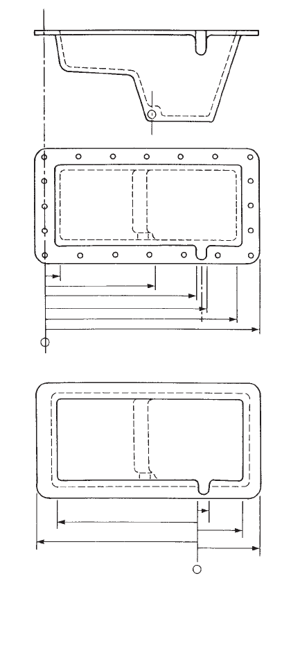
Figure 10.1b shows how these difficulties are
easily resolved. The datum is located against the
side of the dipstick boss, and hence is fixed in its
relation to the casting and goes some way to
halving errors in the two directions from this
plane. It also means that the dipstick boss itself
is now impossible to misplace, no matter how
the casting size varies; all the other dimensions
are allowed to float somewhat because move-
ment of other points on the casting is not a
problem in service. This part can then be pro-
duced easily and efficiently, without trauma to
either producer or customer!
In summary, the rules for the use of datums
(partly from Swing 1962) are:
1. Choose three orthogonal datum planes.
2. Ensure the planes are parallel to the axes of
motion of the machine tools that will be used
to machine the part (otherwise unnecessary
computation and opportunity for error is
introduced).
3. Fix the planes on real casting features, such
as the edges of a boss, or the face of a wall
(i.e. not on a centreline or other abstract
constructional feature). Choose casting fea-
tures that are:
(a) critical in terms of their location, and
(b) as near the centre of the part as possible.
10.2 Location points
Location points are those tiny patches on the
casting that are used to locate the casting pre-
cisely and unambiguously in three dimensions.
They are required by the toolmaker, since he can
construct the tooling with reference to them; the
founder, to check the casting once it has been
made; and the machinist, who uses them to
locate the casting prior to the first machining
operations. These features therefore integrate
the manufacture of the product, ensuring its
smooth transmission as it progresses from
toolmaker to founder to machinist.
Whereas the casting datums are invisible
planes, defining the concept of a zero in the
dimensional space in and around a casting,
the tooling points are real bits of the casting.
The datums are the software, whereas the tool-
ing points are the hardware, of the dimensioning
system. It is useful, although not essential, for
the datums to be defined coincident with the
tooling points.
Location points are known by several dif-
ferent names, such as machining locations
(which is a rather limiting name) or pick-up
points. On drawings, TP for tooling point is
used as the common abbreviation for the
drawing symbol. Although in practice I tend to
use all the names interchangeably it is proposed
that `location points' describes their function
most accurately and will be used here.
Before the day of the introduction of location
points in the Cosworth engine-building opera-
tion, I was accustomed to a complex cylinder
head casting taking a skilled man at least
2 hours to measure to assess how to pick up the
(b)
(a)
Figure 10.1 (a) A badly dimensioned sump, resulting in
a casting that can only be manufactured with difficulty
and with high scrap losses. (b) A sympathetically
dimensioned casting, datumed on the most critical casting
feature, that can be easily and efficiently manufactured.
176 Castings Practice: The 10 Rules of Castings
casting for machining. The casting was repeat-
edly re-checked, re-orienting it slightly with
shims to test whether wall thicknesses were
adequate, and whether all the surfaces required
to be machined would in fact clean up on
machining. After the 2 hours, it was common to
see it, our most expensive casting, dumped on
the scrap heap; no orientation could be found to
ensure that it was dimensionally satisfactory
and could be completely cleaned up on
machining. All this changed on the day when the
new foundry came on stream. A formal system
of location points to define the position of the
casting was introduced. After this date, no
casting was subjected to dimensional checking.
All castings were received from the foundry and
on entering the machine shop were immediately
thrown on to a machine tool, pushed up against
their location points, clamped, and machined.
No tedious measurement time was subsequently
lost, and no casting was ever again scrapped for
machining pick-up problems.
It is essential that every casting has defined
locations that will be agreed with the machinist
and all other parties who require to pick up the
casting accurately.
For instance, it is common for an accurate
casting to be picked up by the machinist using
what appear to be useful features, but which
may be formed by a difficult-to-place core, or a
part of the casting that requires some dressing
by hand. Thus although the whole casting has
excellent accuracy, this particular local feature is
somewhat variable in location. The result is a
casting that is picked up inaccurately, and does
not therefore clean up on machining. As a result
it is, perhaps rather unjustly, declared to be
dimensionally inaccurate.
The author suffered precisely this fate after
the production of a complex pump body casting
for an aerospace application that achieved
excellent accuracy in all respects, except for a
small region of the body that was the site where
three cores met. The small amount of flash at
this junction required dressing with a hand
grinder, and so, naturally, was locally ground to
a flat, but at various slightly different depths
beneath the curved surface of the pump body.
This hand-ground location was the very site that
that machinist chose to locate the casting. The
result was disaster. Furthermore, it was not
easily solved because of the loss of face to the
machinist who then claimed that the location
options suggested by the foundry were incon-
veniently awkward. The fault was not his of
course. The fundamental error lay in not
obtaining agreement between all parties before
the part was made. If the location point used by
the machinist really was the only sensible option
for him, the casting engineer and toolmaker
needed to ensure that the design of the core
package would allow this.
Ultimately, this Rule is designed to ensure
that all castings are picked up accurately, and
conveniently if possible, so that unnecessary
scrap is avoided.
Different arrangements of location points are
required for different geometries of casting. Some
of the most important systems are listed below.
10.2.1 Rectilinear systems
1. Six points are required to define the position
of a component with orthogonal datum
planes that is designed for essentially recti-
linear machining, as for an automotive
cylinder head or block. (Any fewer points
than six are insufficient to define the position
of the casting, and any more than six will
ensure that one or more points are potentially
in conflict.)
On questioning a student on how to use a six-
point system to locate a brick-shaped casting,
the reply was `Oh easy! Use four points around
the outside faces and one top and one bottom.'
This shows how easy it is to get such concepts
wildly wrong!
In fact, the six points are used in a 3, 2, 1
arrangement as shown in Figure 10.2. The sys-
tem works as follows: three points define plane A,
two define the orthogonal plane B, and one
defines the remaining mutually orthogonal
plane C (Figure 10.2). The casting is then picked
up on a jig or machine tool that locates against
these six points. Example (a) shows the basic use
of the system: points 1, 2 and 3 locate plane A;
points 4 and 5 define plane B; and point 6
defines plane C. Planes A, B and C may be the
datum planes. Alternatively, it is often just as
convenient for them to be parallel to the datum
planes, but at accurately specified distances away.
Clearly, to maximize accuracy, points 1, 2 and
3 need to define a widely based triangle, and
points 4 and 5 similarly need to be as widely
spaced as possible. A close grouping of the
locations will result in poor reproducibility of the
pickup of the casting; tiny errors in the position
or surface roughness of the tooling points would
be magnified if they were not widely spaced.
Example (b) shows an improved arrangement
whereby the use of a tooling lug on the long-
itudinal centreline of the casting allows the
dimensions along the length of the casting to be
halved. The largest dimension of the casting is
usually subject to the largest variability, so
halving its effect is a useful action.
Rule 10. Provide location points 177