Japanese National Committee on Large Dams. Dams in Japan, No. 10
Подождите немного. Документ загружается.

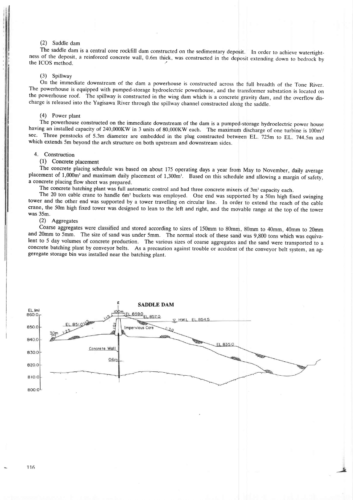
(2)
Saddle
dam
The saddle
dam
is a central core
rockfill
dam
constructed on the
sedimentary
deposit.
In order
to
achieve watertight-
ness
of the
deposit,
a reinforced
concrete
wall,
0.6m thick, was
constructed
in the ieposit
extending
down
to bedrock
by
the
ICOS
method.
(3)
Spillway
On the
immediate
downstream
of the
dam a
powerhouse
is constructed
across
the
full breadth
of the
Tone River.
The
powerhouse
is
equipped
with
pumped-storage
hydroelectric
powerhouse,
and the
transformer
substation
is located on
the
powerhouse
roof.
The
spillway is
constructed
in the wing
dam which is
a concrete gravity
dam,
and
the over{low
dis-
charge
is released
into
the Yagisawa
River through
the
spillway channel
constructed
along the
iaddle.
(4)
Power plant
The
powerhouse
constructed on
the immediate
downstream of the
dam is a
pumped-storage
hydroelectnc
power
house
havirg
an installed
capacity
of 240,000KW
in 3 units
of 80,000KW each.
The maximum
discharge
of
one turbine
is 100m1
sec.
Three
penstocks
of
5,3m diameter
are embedded in the
plug
constructed
between
EL. 725m
to EL.7zl4.5m
and
which
extends
5m beyond
the
arch structure
on both upstream and downstream
sides.
4.
Construction
(1)
Concrete
placement
The
concrete
placing
schedule
was
based
on
about 175
operating
days
a
year
from
placement
of
1,000m3
and
maximum
daily placement
of
1,300m3.
Baied
on
this
schedule
a concrete
placing
flow
sheet was prepared.
May
to
November,
daily
average
and
allowing
a margin
of
safety,
The concr€te
batching
plant
was
full automatic
control and bad
three concrete
mixe$
of
3m'capacity
each.
The
20
ton cable
crane to handle
6mr buckets
was employed.
One end was
suppo
ed uy
a SOm irigtr
fixed
swinging
tower
and
the
other
end was supported
by a tower travelling
on circular
line. In order
to
eitend
the rlach
of the cable
crane,
the
50m
high fixed
tower was
designed
to lean
to the left and dght,
and the
movable
range
at the
top of the rower
was
35m.
(2)
Aggregates
_
Coarse
aggregates
were
classified
and
stored according
to sizes of 150mm
to
80mm,
80mm to 40mm,
40mm
to 20mm
and
20mm
to 5mm.
The size of sand
was
under 5mm. The
normal stock
of these
sand was
9,800
tons which
was equiva-
lent
to 5
day volumes
of concrete production.
The various
sizes of coarse
aggregates
and
the sand were
transported to a
concrete
batching plant
by conveyor
belts.
As a
precaution
against trouble
or accident
of the
conveyor
belt sysrem,
an ag-
Seregate
storage
bin was
installed near
the batching
plant.
EL
(m)
SADDLE
DAM
)
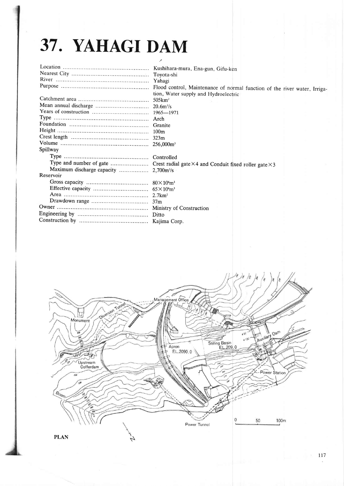
37.
YAHAGI
DAM
Location
Nearest
City
.
River
Purpose
Catchment
area
Mean
annual
discharge
Years
of construction
.
Type
Foundation
Height
Crest
length
Volume
Spillway
Type
Type
and
number
of gate
Maximum
discharge
capacity
Reservoir
Gross
capacity
80X
101n3
Effective
capacity
65
X
106m3
Area
2.7km2
Drawdown
range
37m
Owner
Ministry
of Construction
Engineering
by
Ditto
Construction
by
Kajima
Corp.
t
Office
Kushihara-mura,
Ena-gun,
Gifu-ken
Toyota-shi
Yahagi
Flood
control,
Maintenance
of normal
function
of
the
river water,
Irriga-
tion, Water
supply
and
Hydroelectric
505km'?
20.6m'ls
7965-197r
Arch
Granite
100m
323m
256,000m3
Controlled
Crest radial
gatex4
and
Conduit
fixed
roller
sateX3
2,700m3/s
Upstream
Cofferdam
Basin
EL.209.0
-' ,a
--l':'u"------;--l.z-
\ ,t''t+
-
-"-/-
-'-'
Y.12
1-
Piler
St",ion
-^\
tL7
PLAN
TYPICAL CROSS SECTION
ELgN
+-NWL-EL2S
EL2g)
EL2EO
EL 270
EL-26O
LWL
EL26r.0
EL
253
7
EL 250
EL2{O
€L2il
eL_m
ELjlo
InsPection
GallerY
ELffi.O
EL2@
Primary consolilatron
grouting
Curtain
groutirg
I
I
I
118
&.
Secondary
consolidation
grouting
l.
Geology
of the dam
site
The foundation
of the
dam is
fairly sound granite,
and is better downward
and
on the
right
bank than
the 1eft. On
the
river
bed,
green
colored granite
which
is
affected by the hydro-thermal
action
distributes
irrlgularly.
2. Design
(1)
Abstraction
The dam
is
designed flat
to transmit
the
thrust to the abutment
most and to
make
the foundation
width
which is
essen-
tial
for
the
stability
of the dam
wide.
Fortunately we
have a calculation
program
of a stress
distribution
of
an arch dam on
computer
in
Ministry
of Construction,
and
could analyze the one
of Yahagi Dam
instantly.
We
made sure
that the
para-
bolic
arch
is the
best from the
analysis
by computer
and the model test.
(2)
Adoption
of
parabolic
arch
So far,
it is said
that the central
angle
of the arch is desirable
to range ftom
110 to
120 degree
in view
of a
good
stress
distribution.
But
this is a case when
we pay
attention to the
stress distribution
of the
dam
body only.
When;e want
to
realize
a balanced
security
on the stress
dist
bution including foundation, it
is more
desirable
to direct
the arch
thrust to
th€
abutments
than
to make
the central
angle wide as mentioned
above. M.
O. C.
has found
out that
it is
Dossible
to
make
the
arch
thrust direct
to the
abutments rock
mass most and consequ€ntly
to
make the
width of foundation
wide
through
making
the central
angle na[ow
around 70 degree after
the design of Kawamata
dam.
A
problem
w€
encounter when
we design
a flat arch dam with narrow
central
angle is that
the tension
on the down-
stream
side
of
the
crown increases
because
the bending moment
increases.
As
for
this problem,
it
was
shown
that the
bending moment
could
be reduced
by
reducing
the curvature
radii of an
arch,
after
the
study
on
the stress
distribution
of Yagisawa dam.
Therefore
making
the
curvature
radii
small around
the
crown
of the
arch,
we
can
angle
free
from
stress problems.
One
of the
continuous smooth curves
which
reduce
ment
to
the
crown
is
a
parabolic
arch
for
Yahagi dam.
3.
Treatment
of foundation
Consolidation
grouting
was
done dividing
the
process
into two steps,
primary
grouting
and the secondary
grouting.
Primary
grouting
was
carried out when
the concrete lift was
within 6m to 10m
on a
given
hole. The
grout
holes were
arranged
in
the 3m
apart along the dam
axis, 5m deep and 1,900m long
in total by
the
packer
grouting
method
under a
pressure
of less than
3kg/cm'.
Secandary
consolidation
grouting
was
extended to the depth of 15m
under foundation
surfac€.
The holes were
drilled
on 3m
apart
and angled
forming a fan
shape in a vertical
plane
and
grouted
17,000m
in total length.
The
grouting
was
done
when
the
lift of concrete
on a
given
hote
attened higher than 12m by successive
stage
method
under
rnanmum press-
ure
of 3Okg/cm,.
Curtain gouting
was
carried out in a
single row
with
2m interval by split
space method
and successive
stage method
unde!
a maximum pressure
of 50kg/cm'.
Each
grout
hole
was
50m deep on the
river bed
and 35m on the top
of the abut-
ments
and
the total
number of the holes was
370 and the total length was 18,000m.
The
grouting
was divided
on 3 stages
by elevation,
lower stage, middle
stage and upper
stage.
The
grouting
of lower stage
was done
through the
gallery
and
grouting
tunnel.
Middle and
upper ones were done
through
the
grouting
tunnel. Grout
holes
of upper and middle stage
were
drilled
5m
below the top
of
the
holes of the next lower stage and connected
by supplemental grouting
holes ftom the
next lower grouting
tunnel respectively.
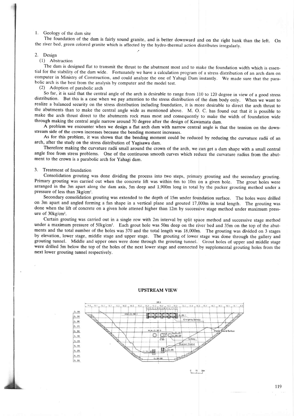
UPSTREAM VIEW
get
a
dam
shape with
a
small
central
the
curvature
radius
from the abut-
ELN
EL 2S
ELM
Et
27A
EL 240
€L 2I
EL 2A
EL
2IO
EL 2@
0 15
30m
trl
r19
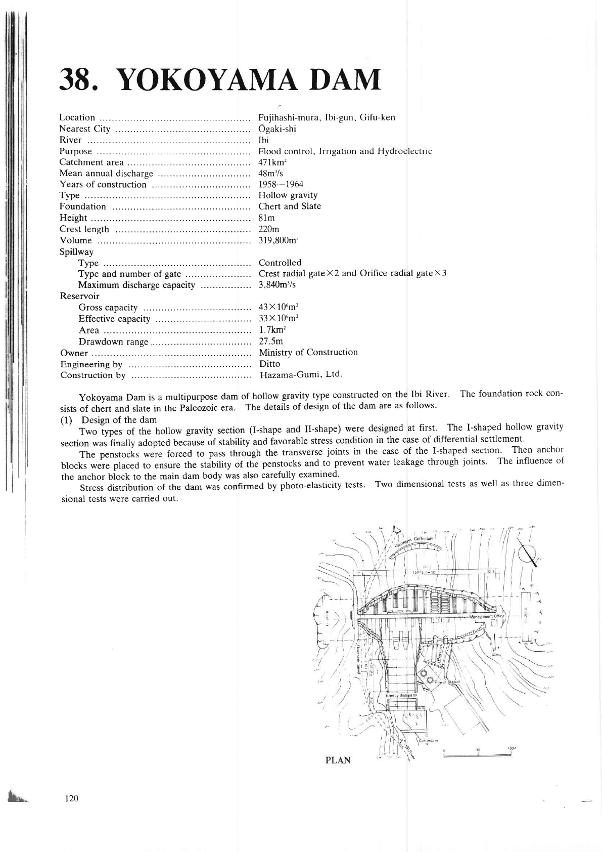
38. YOKOYAIVTA
DAM
Location
Nearest
City .
River
Purpose
Catchment
area
Mean
annual
discharge
Years
of construction
.
Type
Foundation
Height
Crest length
Volume
Spillway
Type ..,............... ...,- Controlled
Type and number of
gate
.............,........
Crest radial
gateX2
and Orifice
radial
gatex3
Maximum discharge capacity
................. 3,840mr/s
Reservoir
Gross capacity ..........
43
x
1trrnl
Effective capacity ..-..
33x 10tn'
Area ..................
..... 1.7km'
Drawdown range.,....................,.....,..,,,
2'15m
Owner .....,..........
.......,...
Ministry of
Construction
Engineering
by
...............
Ditto
Construction
by ...,................. Hazama-Gurni,
Ltd.
Yokoyama
Dam is a
multipurpose
dam of hollo\fl
graYity tyPe
constructed
on
the Ibi River.
The foundation
rock con-
sists of chert
and slate
in the
P;leozoic
era.
The
details
of design
of
the dam
are as
follows'
(1)
Design
of the
dam
' '
Two lypes of
the hollow
gravity section
(I-shape
and
Il-shape)
were designed
at
first. The I-shaped
hollow
gravity
section was frnally
adopted
because
of stability
and
favorable
stress
condition
in
the case of
differential
settlement.
The
penstocis were
forced
to
pass through
the
transvers€
joints
in the
case of
the I-shaped
section-
Then anchor
blocks
weie
placed
to ensure
the sdbility
of the
penstocks
and
to
prevent water
leakage
through
joints.
The influence
of
the anchor biock
to the
main dam
body
was also
calefully
examined'
Stress distribution
of
the
dam was
confirmed
by
photo-elasticity
tests.
Two
dimensional
tests as well
as three dimen-
sional tests
were carried
out.
""G
Fujihashi-mura,
Ibi-gun, Gifu-ken
Ogaki-shi
Ibi,
Flood control,
Irrigation
and Hydroelectric
47tkm'
48m'/s
195&-1964
Hollow
gravity
Ctrert
and Slate
81m
220m
319,800m',
b**
t20
I
r
'
t''
l.
rI
-rlt
rrrl
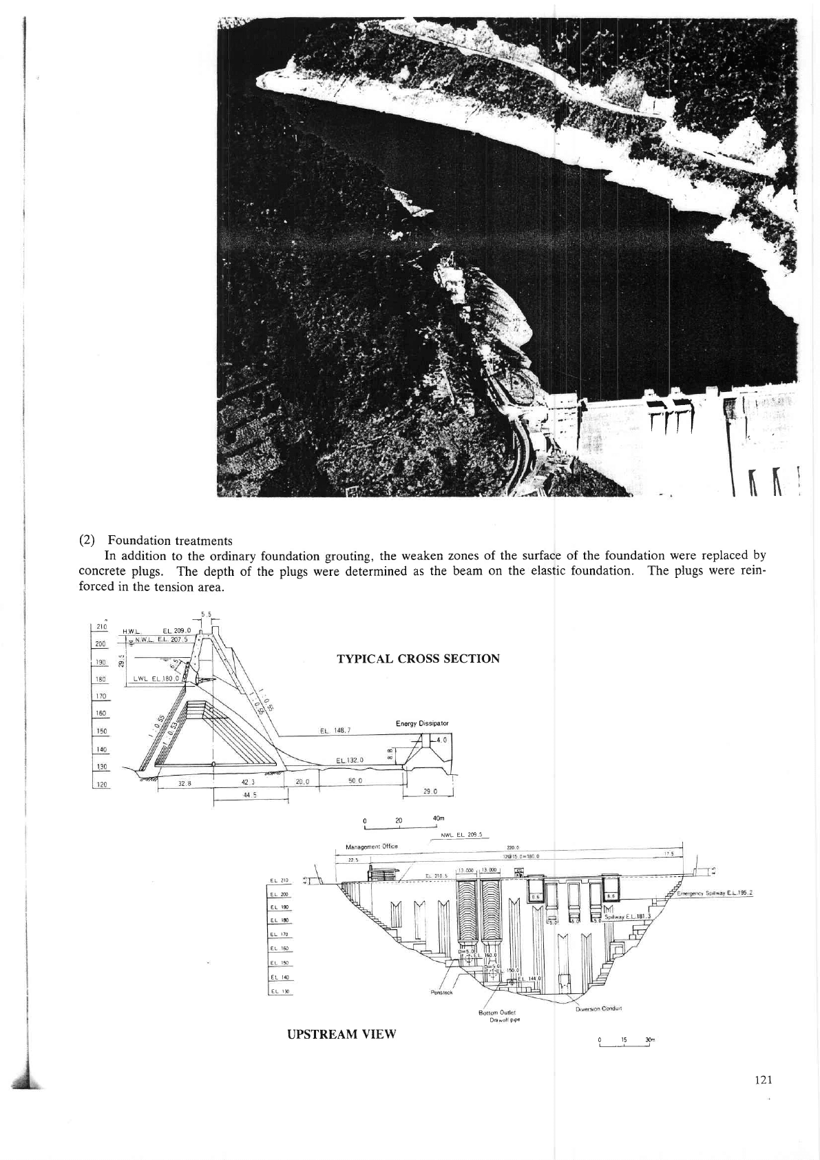
(2)
Foundationtreatments
In
addition
to the
ordinary
concrete
plugs.
The
depth of
forced
in the
tension
area.
foundation
grouting, the
weaken
the
plugs
were
determined
as
the
zones
of the surface
beam
on the elastic
of the foundation were replaced
by
foundation. The
plugs
were
rein-
55
-
-1
FIWL
EL2O9
O
LWL
EL
I8O O
TYPICAL
CROSS SECTION
Energy
Dissipator
o
20
4om
B
mO
Da
PPe
0
15
30n
t21
NWL
EL
209
5
EL
2IO
ELM
€L
190
EL
IEO
EL
170
EL
160
EL
150
EL IlO
EL
IT
UPSTREAM
VIEW
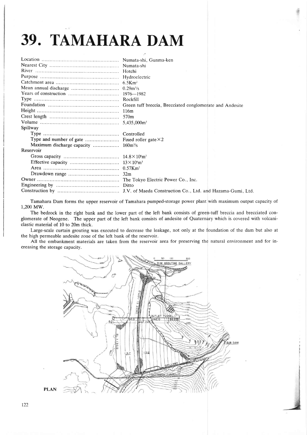
39.
TAMAHARA
DAM
Location
Nearest
City
.
River
Purpose
Catchment
area
Mean
annual
discharge
Years
of construction
Type
Foundation
Height
Crest
length
Volume
Spillway
Type
Type
and
number
of
gate
.
Maximum
discharge
capacity
Reservoir
Gross
capacity
Effective
capacity
Area
Drawdown
range
Owner
Engineering
by
Construction
by
Power Co., Inc.
J.V.
of Maeda
Construction Co., Ltd. and
Hazama-Gumi,
Lt,C.
Tamahara
Dam forms the upper reservoir of Tamahara
pumped-storage
power plant
with
maximum output
capacity of
1,200 MW.
The bedrock in
the right bank and the lower
part of the left
bank consists of
green-tuff
breccia and brecciated con-
glomerat€
of Neogene. The upper
pa
of the left bank consists
of andesite of
Quaternary
which
is covered
with volcani-
clastic
material
of 10 to 20m thick.
Large-scale curtai[
$outing
was
executed
to decrease the leakage,
not only at the foundation of the dam but
also at
the high
permeable
andesite zone of the
left
bank
of the reservoir.
All the embankment
materials are taken from the
reservoir
area for
preserving
the natural environment and for
in-
qeasing
the
storage capacity.
"a-
-\-__---
\
;::\\---=--i
\------:\
r
-\-r--
"--/
/ t
--,,,/7,
''.Jl
Numata-shi, Gunma-ken
Numata-shi
Hotchi
Hydroelectric
6.5Km:
0.29m'ls
r976-1982
Rockfill
Green tuff breccia
116m
570m
5,435,000m'
Controlled
Fixed roller
gateX2
160m3/s
14.8x 10um3
13
X
106m3
0.57Km'?
32m
The Tokyo Electric
Ditto
Brecciated conglomerate
and
Andesite
r22
PLAN
EL.
(
m)
t200
I
t50
iloo
r
o50
rooo
wz
d=
16
==
>(r
<o
| 177.O
@
cone
@
rrlren
@
r rrrr,r
en
@
ouren
@
nrenne
(e.
SH
ELL
SH
ELL
EL.
tO50.o
GROUTI
NG
RY
HW.L.
il73.
wL.
I t4t.
t'.Zj
GROUTING
GALLERY
EXCAVATION
LINE
7.3
zzo
CREST LENGTH 57O.O
77
T
SPILLWAY
EL
(m)
t200
N
IO
ro 50
rooo
TYPICAL
CROSS SECTION
PROFILE
ALONG DAN{
AXIS
r23
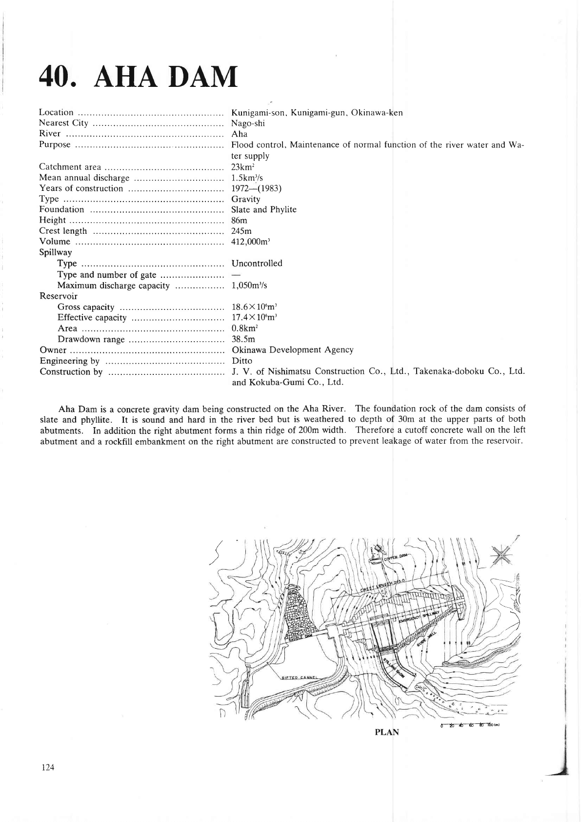
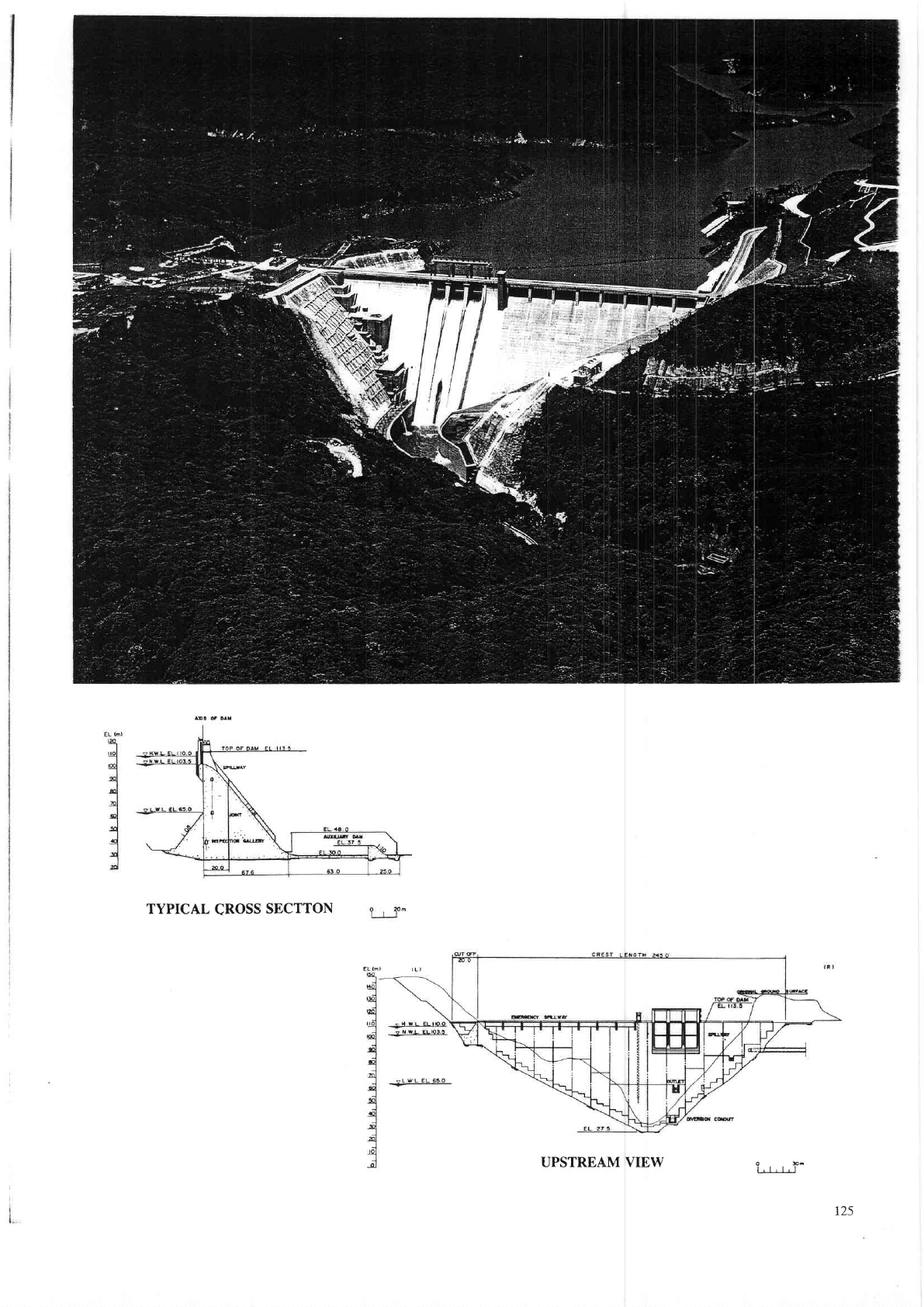
40.
AHA
DAM
Location
Nearest
City
.
River
Purpose
Catchment
area
Mean
annual
discharge
Years
of construction
.
Type
Foundation
Height
Crest length
Volume
Spillway
Type
Type
and number
of
gate
.
Maximum
discharge
capacity
Reservoir
Gross capacity
Effective
capacity
Area
Drawdown
range
Owner
Engineering
by
Construction
bv
Kunigami-son,
Kunigami-gun,
Okinawa-ken
Nago-shi
Aha
Flood control,
Maintenance
of normal function
of the
river
wrater
and
Wa-
ter supply
23km'z
1.5km'/s
re72-(re83)
Gravity
Slate
and
Phylite
86m
245m
412,000m3
Uncontrolled
1.050m'/s
18.6
X
106m3
77.4x 10'm'
0.8km'
38.5m
Okinawa
Development
Agency
Ditto
J. V.
of
Nishimatsu
Construction
Co., Ltd., Takenaka-doboku Co., Ltd.
and Kokuba-Gumi
Co.. Ltd.
Aha
Dam is a conqete
gravity
dam being constuucted
on
the Aha River. The foundation rock of th€ dam
consists of
slate and
phyllite.
It is sound and
hard in the river bed
but is
weathered to depth of 30m at the upper
parts
of both
abutments.
In addition the dght abutment
forms a thin ridge
of 200m
width. Therefore a
cutoff consete
wall
on
the left
abutment
and a rockfill embankment
on the
ght
abutment are
constructed to
prevent
leakage of water ftom the reservoir.
t\
t
iti
C-=-'1'ili
\t--7,
)
\
^Tt
i'---H
.4
PLAN
6--ffi--6--I0ot.t
t24
TYPICAL
qROSS
SECTTON
UPSTREA,M VIEW
O96
l,l,l,l
r25