Japanese National Committee on Large Dams. Dams in Japan, No. 10
Подождите немного. Документ загружается.

2.
Design and
construction
The dam
is adopted
a zone-type rockfill dam with
a central earth
core.
The core
is divided into
two
zones,
cor€ A and core B, in consideration of
quality
maintenance
of core materials.
Core
A is defined
as a zone which ensured imperrneability,-and Core B as a zone in which
heterogeneous
materials
were
permitted.
Only the materials
stored tempomrily in the stock-pile
were
employed to Core A,and
the mate als directly
transported
from the
borrow
pit
wer€ included in Core B.
The very weathered
schist at the the dam site and tbe excavated soils
at
the
foundations
and
quarry-site
were
adopted
to the core
materials.
Hard sandy black schist in the quarry was used for rock materials. The
filter materials were semi-
weathered
rocks
excavated
at the dam site, spillway and
quarry.
Core material
with a maximurn
grain
size of 150mm
was
spread
in thickness of 15cm, and
compacted by 12
passes
of
tamping
rollers. In
the filter zone, the mate al
was
spread in thickness
of
30cm,
and vibrating
rollers
passed
4 times for
compaction,
The thickness
in a range from 0,5m to 1.5m and
4
pass
compaction by vibrating
rollers were applied to the
rock zone.
3.
Foundationtreatment
(1)
Curtain grout
The curtain grouting
was caried out in two rows with a space of 1.5m in the
portion
from the dver bed
to
the fight-
side
abutment,
and in three
rou,s
with a
space of 0.75m
each io the
portion
of the left-side. Holes were drilled
i\
a zigz
g
line and with
an interval of 3.0m for both sides.
(2)
Blanket
grouting
Grout holes
were ddlled 5.0m deep in a space of 3.0m
or 5.0m in the foundation of Core A.
Grouting
was also
needed
properly
for
the
potion
of major
fissue in the foundation of Core
B.
Since
corking was
not effective for leakage of
cement-milk
due to the weakness of rock, mortar
was
sprayed over
the foundation face of Core A
(t:scm)
before
grouting
to cope with
the leakage.
The sprayed
mortar was removed before
embankment. The
grouting
was
pedormed
after the
surface layer had
been consolidated by
gouting with
a
hole depth of lm or 2m, a hole-interval of lm and an injection
pressure
of 1 or 2 kg/cmr.
(3)
Supplemental grouting
Ahead
of curtain
grouting,
supplemental blanket
grouting
was made covedng
the whole
imferrious zone by
a hole-
depth of
5m
with
a hole.int€rval
of
3 or 5m.
The total length
of
gouting
curtain
is about
66,000m,
including
supplemental blanket
gouting,
and the
blanket
grout-
ing extends about
7,000m in length.
(4)
Treatment
of shear zone
A shear zone which
had a
width of 45m in the middle
part
of th€ right abutment.
The
shear zone was wholly
weak,
since
faults with
a dip of about 45'were
involved in
parallel with the schistosity and
graphite
schist
was
included
therein.
The faults were
so aged and compacted that only the
loose rocks were
excavated, without replacement by conqete or core
matedal.
Since there seemed
to be a
possibility
of non-uniforrn
settlement
of the
shear
zone, two rock-extensometers were set
after completion of embankment, and now keep on observation.
The results of
measurement
at
present
show
only about
lmm settlement
at the both
points,
and transformation
of the
gallery
is not observed, which
verifies
that the treatment
of
foundation
rock has been done successfully.
(5)
Treatment
of foundation
surface
The following
treatment
was
taken
up for the core
{oundation
surface after cleaning thereof.
First of
all, cement-milk was
poured
from the sudace
to the
fissure which could not be treated by blanket
grouting.
Water was
sprinkeled
enough on
the foundation
just
before embankment
so that the
foundation
might not absorb
water
from the embankmbnt
materials. Clayisb
slurry
rvas
spread
in a depth
of 2mm-5mm to bring about the following
effects
;
(a)
Impermeability is more assured by smoothing
the small
concaves of the suface.
(b)
Spread
stabilizing mate als
can be distributed
even to
the small concaves because
the
slurry
acts as lubricating
oil, and
(c)
Plasticity
of stabilizing
materials can be assured
because
the
foundation rock can absorb
water
from the
slurry.
After spreading clayish slurry, stabilizing
materials
were
provided by manual labor and compacted by
mechanical
tam-
pers
to the maximum
thickness of
7.5cm for each layer.
106
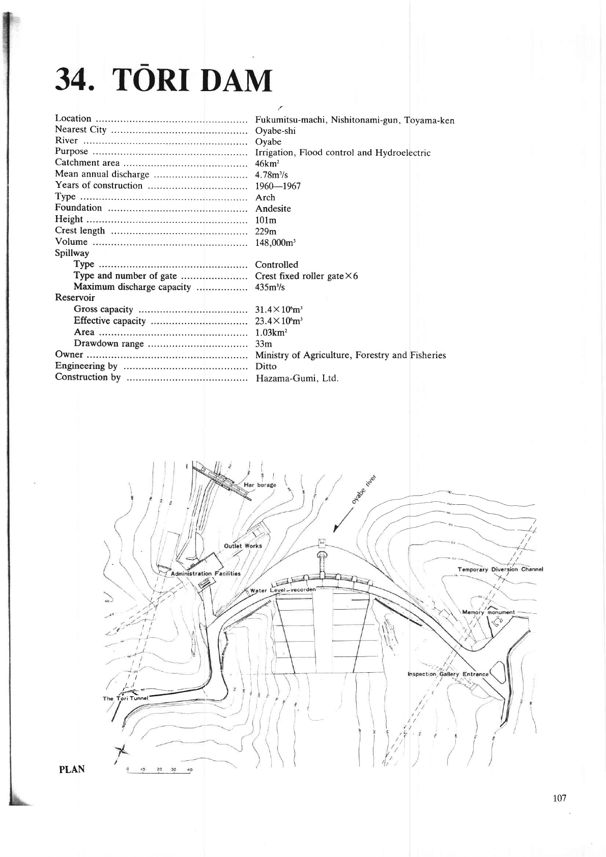
34.
TORI
DAM
Location
Nearest
City
.
River
Purpose
Catchment
area
Mean
annual
discharge
Years
of construction
.
Type
Foundation
Height
Crest
length
Volume
Spillway
Type
Type
and
number
of
gate
.
Maximum
discharge
capacity
Reservoir
Gross
capacity
Effective
capacity
Area
Drawdown
range
Owner
Engineering
by
Construction
bv
Fukumitsu-machi, Nishitonami-gun,
Toyama-ken
Oyabe-shi
Oyabe
Irrigation, Flood
control
and Hydroelectric
46km'?
4.78m'/s
196A-1967
Arch
Andesite
101m
229m
148,000m3
Controlled
Crest fixed
roller
gate X
6
435m3/s
31.4X
106m3
23.4X
10'm3
L.03km2
33m
Ministry of
Agriculture,
Forestry
and
Fisheries
Ditto
Hazama-Gumi.
Ltd.
/-7=---=..---
/r-t-.-""+
/
l----",-"'
.
\-=--
-t1
.L-I
4
<{,1#"i"
-
.
Y\\
\Mem.ory
monument
\ l^: ,Z:=
, \o.
\
l\
tt
4/
PLAN
107
r08
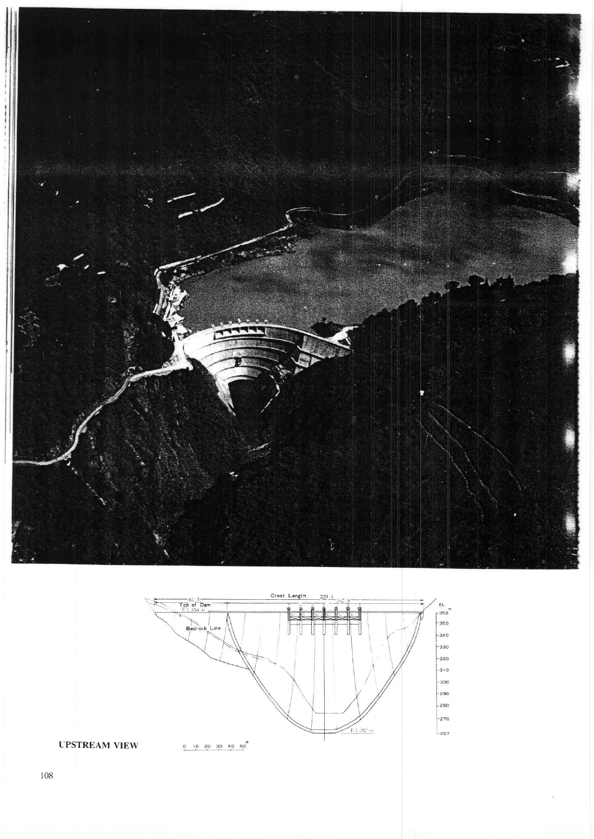
UPSTREAM
VIEW
The
foundation
of the dam consists
of amphiboles and
pyroxenic
andesite
lava belonging
to Yatsuo
group
of Neogene
Miocene
Era.
Detailed geological
surveys
confirmed
that the foundation is hard and
sound for
an arch
dam.
Final decision was
made
after
elimination
of other types
of dams on the following
grounds.
1
Gravity dam
would double
in
volume,
and aggregate is not available near
the dam
site in
the required quantity.
2 The
topographic
condition is
not favorable for a fill dam
because of the thin
abutments
of both
banks. In case of a
fill dam,
the volirme would
be bigger
than ordinal and there is no
good
site for the
spillway.
Dome
shape
arch was
selected mainly
reflected by topographical considerations
and
planning
of the spillway, which
was
designed
of the center overflow
type.
Upper
Part
of left abutment
slopes rather gentle
and
presents geological
weakness
in
comparison
with right
abutment.
Therefore,
a thrust block was
constructed on
this
part
to make the arch symmetry
and to reduc€
the
stress of abutment.
Structural
model tests were
repeated to confirm
the safety of the dam. Condition
of stress
both in
the foundation and
in
abutment
were
investigated by
photoelastic
tests. Hydraulic model
tests
were
also
peformed
to analyze the flow condi-
tion
of the
spillway.
Consolidation
and cudain
grouting
was
executed to improve the dam foundation,
and
also
contact
grouting
was
ex-
ecuted
at the
contact of dam body
and abutment.
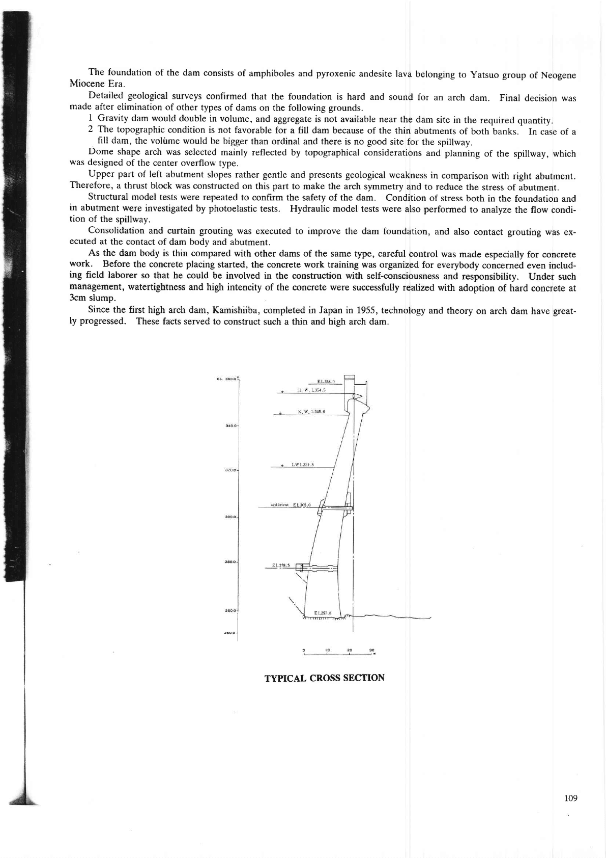
As the dam
body is thin compared
with other dams of the same type, careful
control was
made
especially for concrete
work.
Beforc
the concrete
placing
started, the conqete work training was
organized for
everybody
concemed even includ-
ing
field
laborer
so that he could be involved
in the constuction
with
self-consciousness
and
resDonsibilitv.
Under such
management,
watcrtightness
and
high intencity of the mncrete were
succesfirlly realized with
adoption
of hard mnqete at
3cm
slump.
Since the first
high arch dam, Karnishiiba,
completed in Japan in 1.955, technology
and theory
on arch dam have
great-
ly
progressed.
These fdcts served to
construct such a thin
and high
arch
dam.
TYPICAL
CROSS
SECTION
."""]
109
35.
UCHINOKURA
DAM
Location
Nearest
City
.
River
Purpose
Catchment
area
Mean
annual
discharge
Years
of
construction
Type
Foundation
Height
Crest
length
Volume
Spillway
Type
Type
and
number
of
gate
..
Maximum
discharge
capacity
Reservoir
Gross
capacity
Effective
capacity
Area
Drawdown
range
Owner
Engineering
by
Construction
by
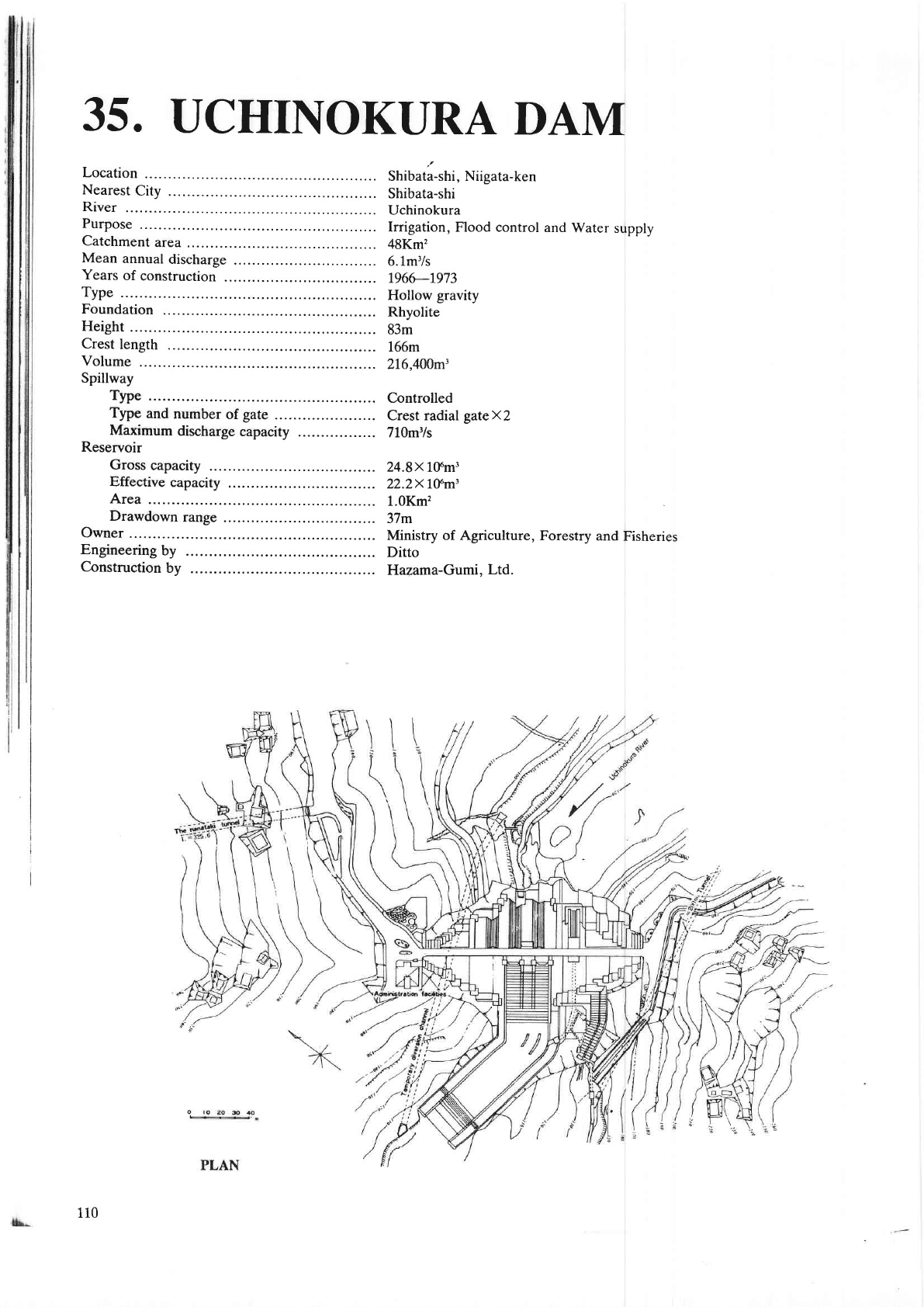
Shibata-shi, Niigata-ken
Shibata-shi
Uchinokura
Irrigation,
Flood control
and
Water
supply
48Km'
6.1m3/s
1966-1973
Hollow
gravity
Rhyolite
83m
166m
216,400m3
Controlled
Crest radial
gateX2
710m3/s
24.8x
1ffm3
22.2x 1ffm'
1.OKm'?
37m
Ministry of Agriculture,
Forestry
and
Fisheries
Ditto
Hazama-Gumi.
Ltd.
110
111
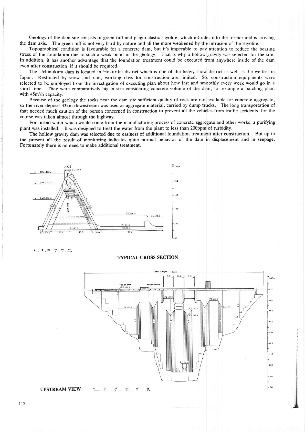
Geology of
the dam site consists of
green
tuff and
plagio-clastic
rhyolite, which intrudes into the former
and
is crossing
the dam
axis. The
green
tuff is not
very
hard by nature and
all the more weakened by the intrusion
of the rhyolite.
Topographical
condition is favourable for a concrete
dam, but it's imperable to
pay
attention to
reduce the bea
ng
stress
of the foundation
due to such a
weak point
in the
geology.
That is
why
a hollow
gravity
was
selected
for the site.
In
addition, it
has another advantage that the foundation treatment
could be executed from anywhere inside of the dam
even after
construction, if it should be required.
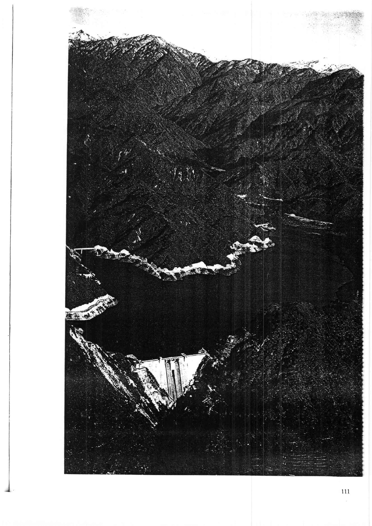
The
Uchinokura
dam is located
in Hokuriku district which is
one of the heavy snow district as well
as the
wettest in
Japan. Restdcted
by
snow
and rain, working days for construction
are limited. So, construction equipments
were
selected
to be employed
ftom the
investigation of executing
plan
about how fast and smoothly every work would
go
in a
short time.
They were comparatively big in size considering
concrete
volume of the dam, for
example a batching
plant
v/ith 45m3/h
capacity.
Because
of the
geology
the
rocks near the dam site sufficient
quality
of rock
are not
available for concrete a14fe91te,
so the ver deposit
33km downstream
was used as aggregate material,
carried by dump trucks. The long transportation of
that needed
much
cautioq of
the
person
concerned in construction
to
prevent
all the vehicles ftom traffic
accidents,
for the
course
was taken
almost through
the highway.
For turbid water
which would come
ftom the manufacturing
process
of concrete
aggregate and other works, a
purifying
plant
was
installed.
It
was designed to treat the water from
the
plant to less than 200ppm of turbidity.
The
hollow
gravity
dam was selected due to easiness
of additional
foundation treatment after construction. But up
to
the
pr€sent
all
the result of monitoring
indicates
quite
normal
behavior of
the dam in displac€ment and in seepage.
Fortunately there is
no need
to make additional treatment.
?_-_lf _,_1_-_T.-_f
_.=1'.
TYPICAL
CROSS
SECTION
it
*'
t
frzo
I
I
f""
I
t'*
].-,
oo
I
t
['"'
I
I
Ts
ol Om
ttz
UPSTREAM
VIEW
36.
YAGISAI4{A
DAM
Location
Nearest
City
.
River
Purpose
Catchment
area
Mean
annual
discharge
Years
of construction
.
Type
Foundation
Height
Crest
length
Volume
Spillway
Type
Type
and number
of
gate
Maximum
discharge
capacity
Reservoir
Gross
capacity
Effective
capacity
Area
Drawdown
range
Owner
Engineering
by
Construction
by
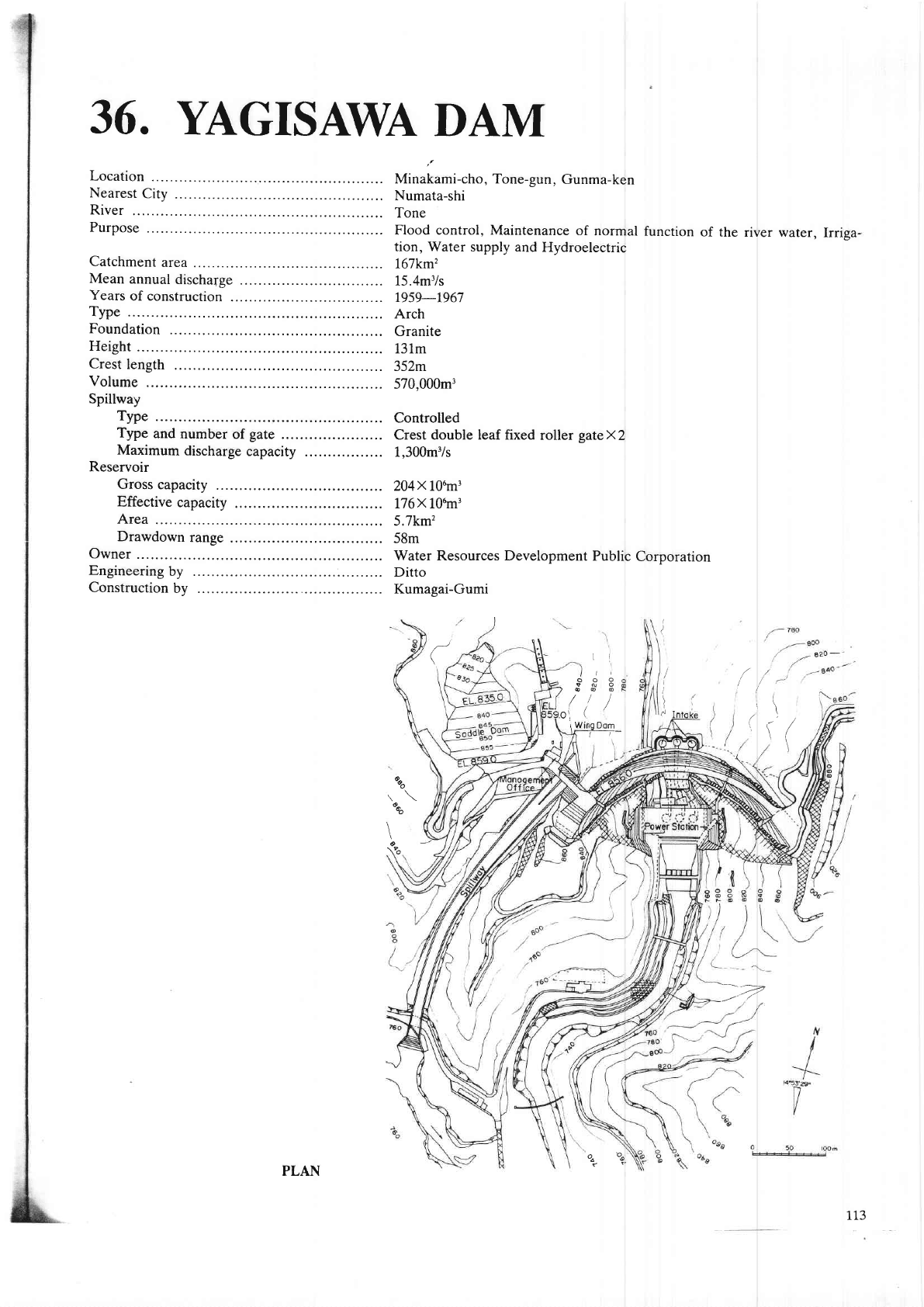
Minakami-cho, Tone-gun,
Gunma-ken
Numata-shi
Tone
Flood control,
Maintenance
of
normal
function
of the
river water,
Irriga-
tion, Water
supply and
Hydroelectric
167km'1
15.4m3/s
1959-t967
Arch
Granite
13lm
352m
570,000m3
Controlled
Crest double leaf fixed
roller
gateX2
1,300m3/s
204x 106m3
176X- L06rn3
5.7km'?
58m
Water Resources Development
Public
Corporation
Ditto
Kumasai-Gumi
(
(
\
\
I
)
r.l
rl
tuo
a@
rg
Dom
(
o
)a
o\
rW
I
(
%o
o^
It
o
\oo
-"-v
PLAN
%.
%.
113
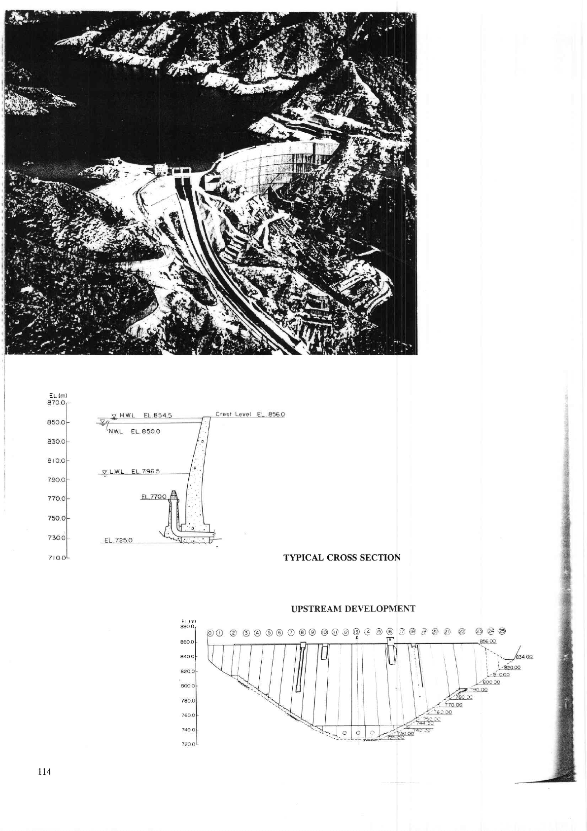
TYPICAL
CROSS
SECTION
EL
(m)
::::i
840.Or
UPSTREANI
DEVELOPMENT
o@o@o@@@@@o@e@
La
rt4
1. Topography
The
Tone
River
flows from north
to south
at the dam site
through
a
gorge
where
both abutments
are
sloped at an
angle
of 40
to 45
degrees
from the
river bed,
forming a
"v" shape valley.
The
contours
of the
rock
foundation
of both
banks
are
parallel
to the river flow
and
present
a topography
suited
for construction
of
an arch
dam.
2.
Geology
The
foundation
of the dam is
sound
granite
(Yagisawa granite),
but the surrounding
granite
(sudagai
granite
is easily
susceptible
to weathering.
The rock
at the
river bed is
sound and hard,
but at higher
elevations,
weath-ering
has advanced
and
many cracks
have
developed,
On
the left abutment
near the
crest of the
dam, the
boundary
of the weathered
zone is
evident,
rest cting
the alignmeDt
of the arch
abutment.
On the right
abutment,
between
EL.
860m and
870m, there
is the
top
of
a thiD
ridge,
and to the right
side of
the ridge there is a
saddle covered with
sedimentary
deposit
approximately
50m
deep
and
extending
about
130m. Bedrock
underlying
the
deposit
is
good
Yagisawa
granite
of itt"
q,rutity
found
at the
damsite.
The elevation
of the
deepest
part
of the deposit on the
bedrock is
800m to
810m, and
the existence
of this
saddle
was
the
factor
which determined
the
height of
yagisawa
Dam.
3. Design
_
Yagisawa
Dam
project
consists
of a main arch
dam of 131m high, assisted
by
a saddte
(fill)
dam
and a
wing (concrete)
dam
on the
dght
bank in which
the spillway
is installed.
The
crest of
the dam is selected
to the
highest elevation, which
will be
permissibte
by the engineedrg
judgement
from
geological
as lYell
as topographical point
of vie\f,.
The crest of the dam
is EL.
856m and
the resJrvoir
criited
by the dam
will
be able
to control
the annual
inflow into
the reservoir. The location
of the
power
house
and the
type of the
spillway
are
also taken
into
consideration.
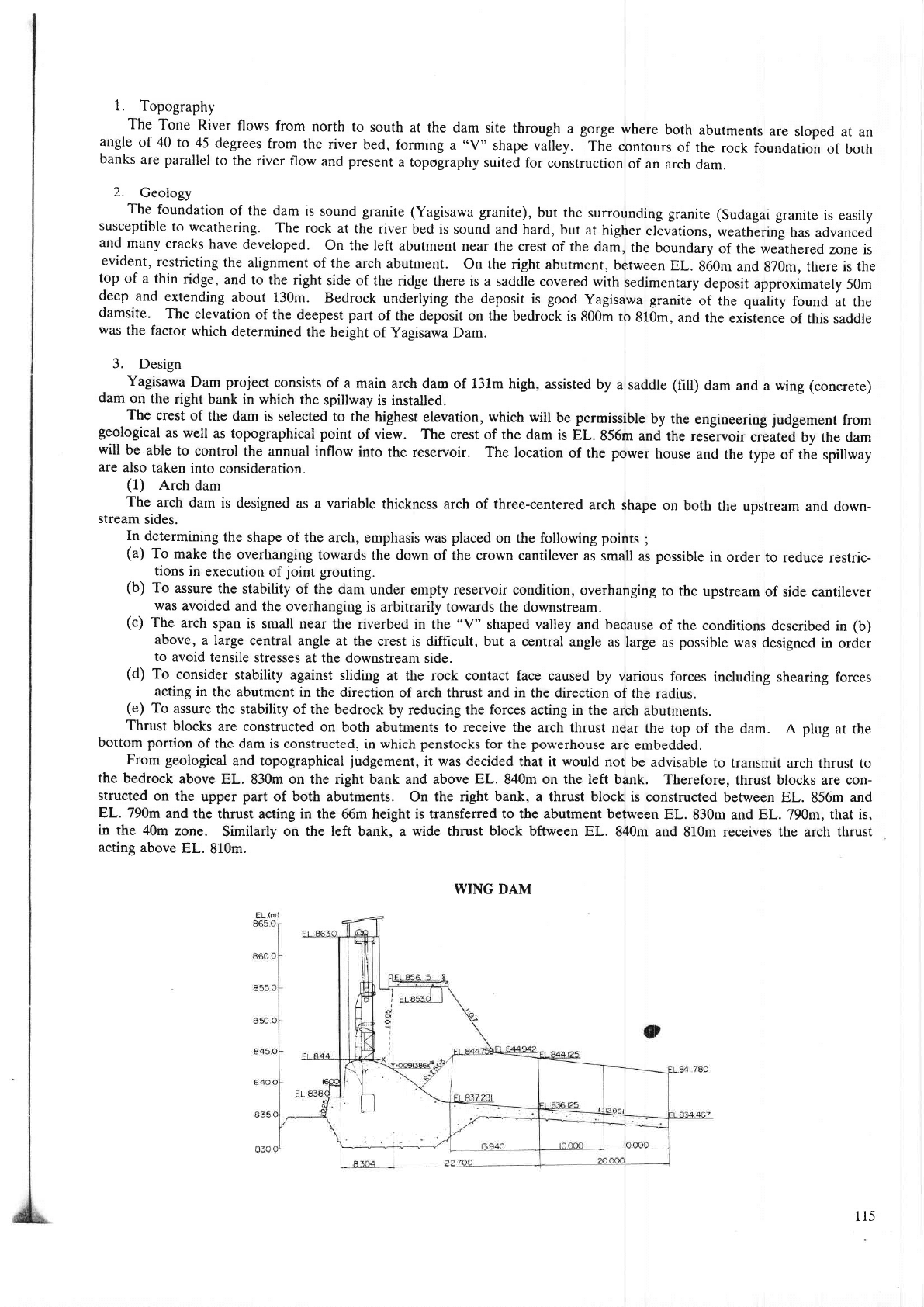
(1)
Arch
dam
The
arch
dam is designed
as a variable
thickness arch of three-centered
arch
shape
on both
the upstream
and down-
stream
sides,
In determiniog
the shape of
the arch, enphasis was placed
on the following
points
;
(a)
To make
the overhanging
towards
the down of the crown cantilever
as small
as
possible
in order to
reduce restdc-
tions
in
execution of
joint
grouting.
(b)
To
assure
the stability of
the dam under
empty reservoir condition, overhanging
to the upstream
of side cantilever
$,as
avoided
and the overhanging
is arbitra ly ton'ards the downstream.
(c)
The
arch
span is small near
the dverbed in the
"V"
shaped valley
and because
of the
conditions described
in
(b)
above,
a large central
angle at the crest is difficult, but
a central angle as
large as
possible
was designed
in order
to
avoid tensile
stresses at the downstream
side.
(d)
To
consider
stability against sliding
at the rock contact face
caused by various
forces
including shearing forces
acting
in the abutment in
the direction of arch thrust and in
the direction of thc
radius.
(e)
To
assure
the stability of the bedrock
by reducing the forces
acting in the arch
abutments.
Thrust
blocks
are constructed
on both abutments to receive the
arch thrust near
the top
of the dam. A plug
at the
bottom
portion
of the dam is constructed,
in which
penstocks
for the
powerhouse
are
embedded.
From geological
and topographical
judgement,
it was decided
that it would not
be advisable
to transmit arch thrust to
the
bedrock
above EL.
830m
on the right bank and above EL.
840m
on the left bank.
Therefore,
thrust blocks are con-
structed on
the upper
part
of both abutments.
On
the right bank, a thrust block
is constructed
between EL. 856m
and
EL. 790m
and the thrust
acting
in the
66m height
is transfered to the abutnent between
EL.
830m and EL. 790m,
that is,
in
the 40m
zone.
Similarly
on the left
bank, a
wide thrust block bftween EL.
840m and 810m receives the arch thrust
acting
above
EL. 810m.
WING DAM
115