Japanese National Committee on Large Dams. Dams in Japan, No. 10
Подождите немного. Документ загружается.

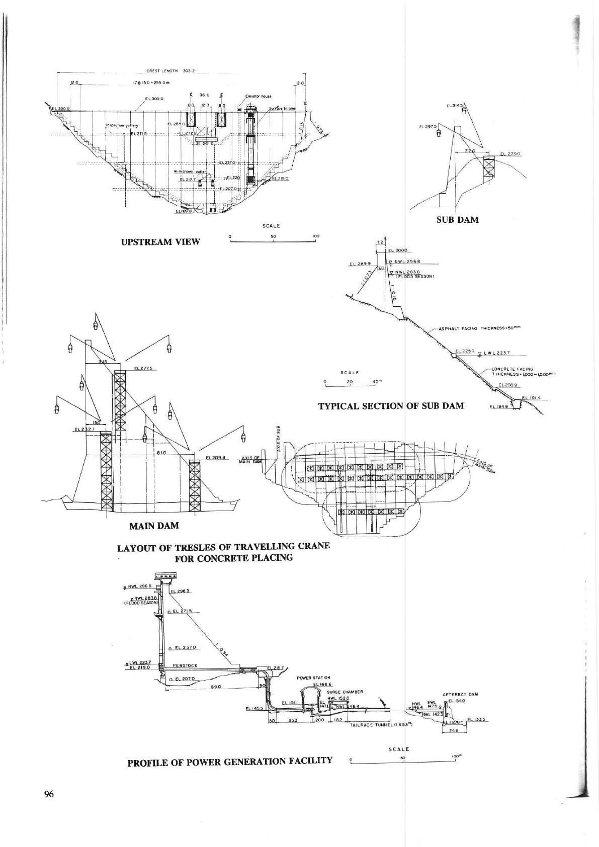
SUB DAM
JLA LE
o
50
loo
UPSTREAM
VIEW
LAYOUT
OF
TR.ESLES
OF
TRAVELLING
CRANE
-
FOR
CONCRETE
PLACING
TYPICAL SECTION
OF
SUB
DAM
CONCRETE
FACING
T
HICKNESS.
I,O@-l,5OOmm
ASPHALT
FACllrG
THICKNESS'soom
MAIN
DAM
96
PROFILE
OF
POWER
GENERATION
FACILITY
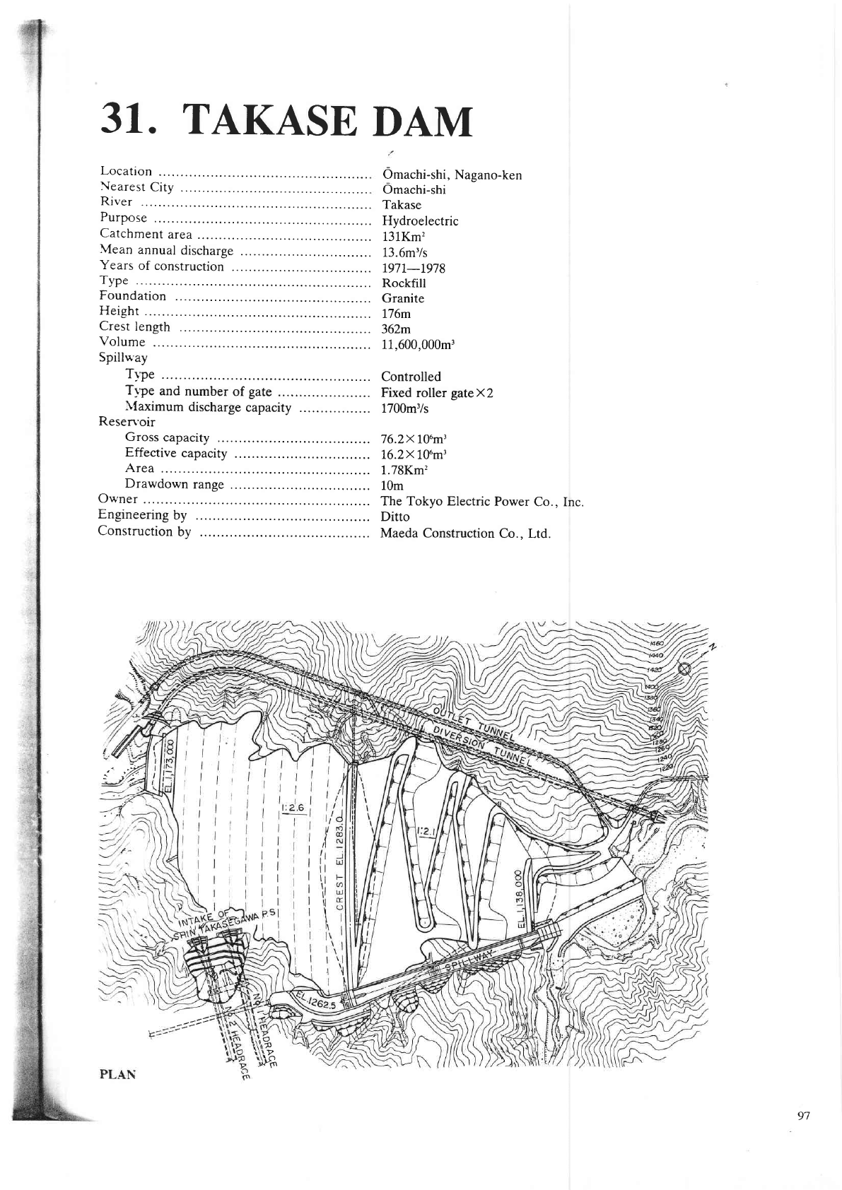
31.
TAKASE
DAM
Location
Nearesr
City
.
River
Purpose
Catchment
area
Mean
annual
discharge
Years
of construction
.
Type
Foundation
Height
Crest
length
Volume
Spillu.ay
T)'pe
Tt'pe
and
number
of
gate
.
I{aximum
discharge
capacity
Resen'oir
Gross
capacity
Effective
capacity
Area
Drawdown
range
Owner
Engineering
by
Construction
by
Omachi-shi,
Nagano-ken
Omachi-shi
Takase
Hydroelectric
131Km'?
13.6m'/s
r97r-r978
Rockfill
Granite
176m
362m
11,600,000m3
Controlled
Fixed roller
gateXZ
1700m3/s
76.2x 10um'
162X
l.0um3
1.78Km'?
10m
The Tokyo Electric
Power
Co., Inc.
Ditto
Maeda Construction
Co., Ltd.
t..
a.
\1
',*
--
J.t-=
!P
P1n
--a>
97
EL.
(m
)
I 300
r2 50
| 200
I t50
I
too
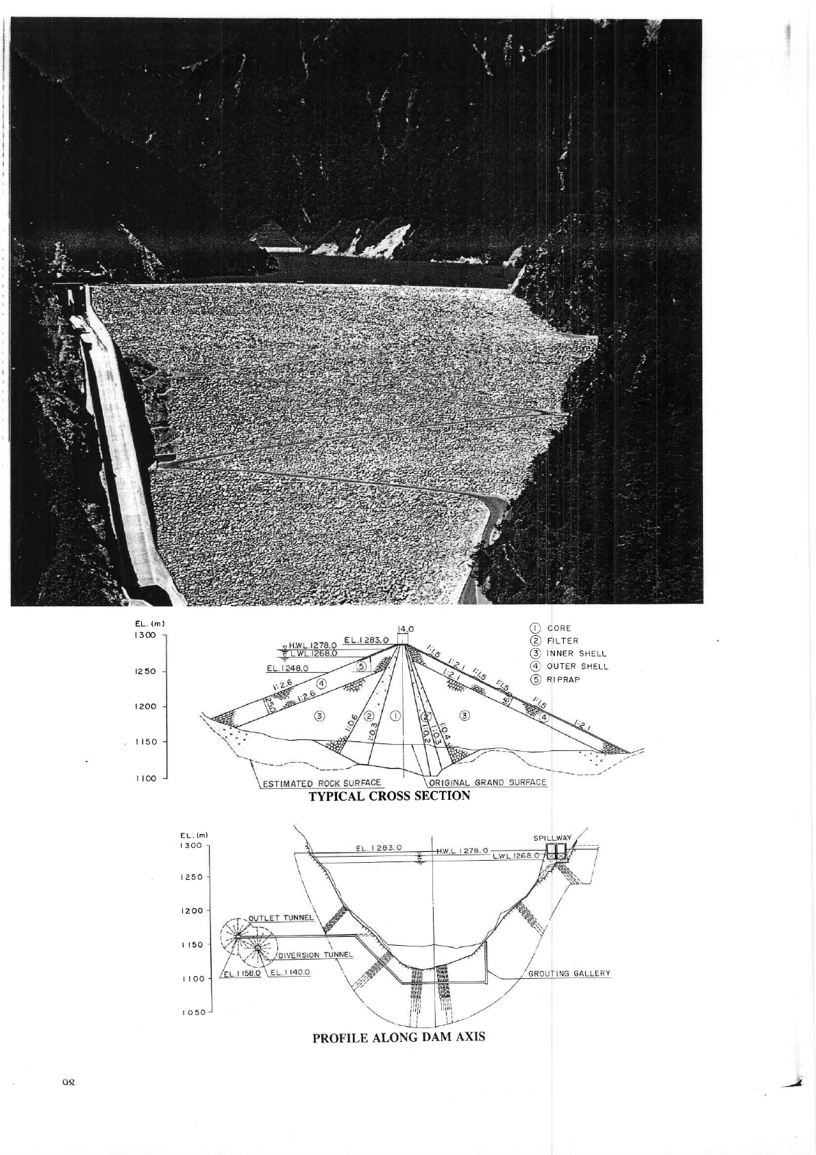
@
conr
@
ntr-ren
/';\ ,.,.,-^ ^,.-,
\9
lr\r\rK
JnELL
6'. ort.trp
qspr
r
\,
--
@
nrenae
I
TYPICAL
CROSS
SECTION
LL.
(M'
r
300
r250
r200
I r50
I too
ro50
PROFILE
ALONG
DAM
AXIS
-J.
of
z.
l.
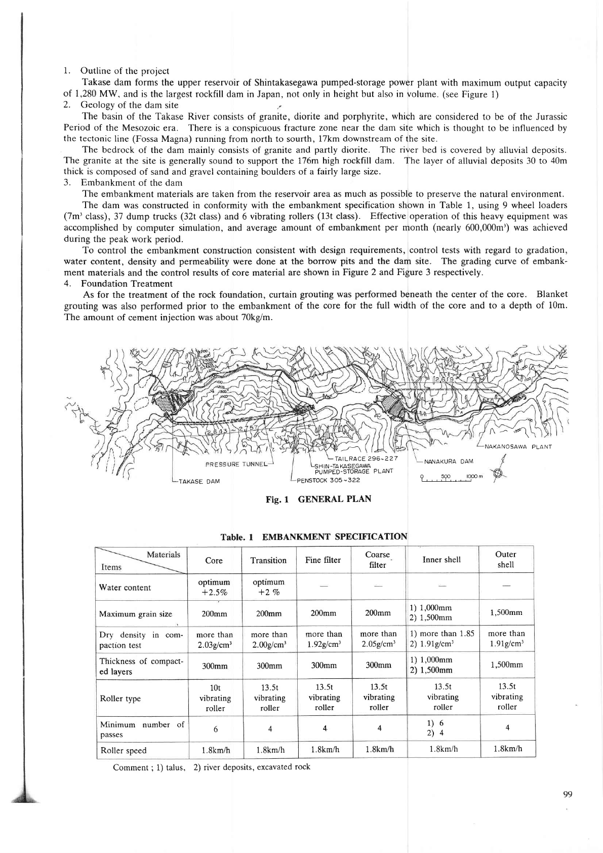
Outline
of the
project
Takase
dam forms the
upper reservoir of Shintakasegawa
pumped-storage power
plant
with
maximum output capacity
1,280
MW,
and
is the largest rockfill dam in
Japan,
not only
in height
but
also in volume.
(see
Figure 1)
Geology
of the dam
site
The basin
of the Takase River consists of
granite,
diorite and
porphyrite,
which
are considered
to be of the Jurassic
Period
of the
Mesozoic era. There is a conspicuous fracture
zone near the dam site which
is thought to be influenced by
the
tectonic line
(Fossa
Magna) running from north to sourth,
17km downstream of the
site.
The
bedrock of the dam mainly consists of
granite
and
partly
diorite. The river bed is covered
by
alluvial deposits.
The
granite
at the site is
generally
sound to support the 176m
high rockfill dam. The
layer of alluvial deposits 30 to
40m
thick
is composed
of sand and
gravel
containing boulde$ of
a fairly large srze.
3. Embankment
of the
dam
The
embankment materials are taken from the reservoir
area
as much
as
possible
to
preserye
the natuml environment.
The
dam was constructed in conformity with the embankment
specification shown in
Table 1, using 9 wheel loaders
(7mr
class),
37 dump trucks
(32t
class) and 6 vibrating
rouers
(13t
class). Effective operation of this heavy equipment
was
accomplished
by computer simulation, and average
amount of embankment
per
month
(nearly
600,000mi)
was achieved
during
the
peak
work
period.
To
control the embankment construction consistent
with design requirements, control tests with regard to
gradation,
water
content,
density and
permeability
were done at the borow
pits
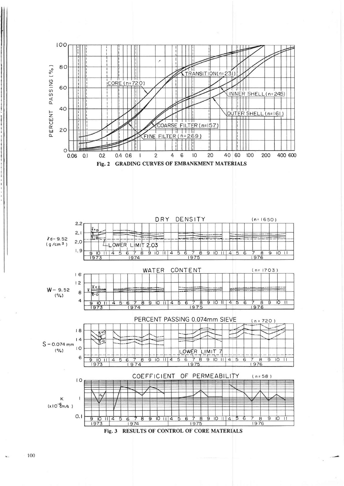
and the dam site. The
grading
curve
of embank-
ment
materials and the conftol results of core material
are shown in Figure 2 and
Figure
3 respectively.
4.
FoundationTreatment
As
for the treatment of the
rock foundation, curtain
grouting was
performed
beneath the center of the core. Blanket
grouting
was
also
performed prior
to the embankment
of the
core for the full
width
of the core and to a depth of
10m.
The amount
of cement
iniection was about 70kgm.
-'*\
NAKANOSAWA
PLANT
TAKASE
DAM
SHIN
-TA
KASEGAWA
PUMPED-STORAGE
PLANT
TAILRACE 296-227
NANAKURA
DAM
?----191---l-.,ooo
PENSTOCK
3O5-322
Fig.
1 GENERAL
PLAN
Table. I EMBANKMENT
SPECIFICATION
Core
Transition
Fine filter
Coarse
filter
Inner shell
Outer
shell
Water
content
optimum
*2.5Vo
optlmum
*2
Vo
Maximum
grain
size
200mm
200mm
200mm
200mm
l) 1,000mm
2) 1,500mm
1,500mm
D.y
density in com-
pactlon
test
more than
2.03glcm3
more than
2.00g/cm3
more
than
1.92glcm3
more
than
2.05glcm3
1) more
than 1.85
2) 1..97g1cm3
more
than
1.91glcm3
Thickness
of compact-
ed lavers
300mm
300mm
300mm
300mm
1) 1,000mm
2) 1,500mm
1,500mm
Roller
type
10t
vibrating
roller
13.5r
vibrating
roller
13.5t
vibrating
roller
13.5t
vibrating
roller
13.5t
vibrating
roller
13.5t
vibrating
roller
Minimum
number
of
passes
6
4
4
4
1)6
2)4
4
Roller
speed
1.8km/h
1.Skm/h
1.8km/h
1.8km/h
1.8km/h
1.8km/h
Comment
;
1) talus,
2) river
deposits, excavated
rock
99
too
;
80
o\
;
z
(/'60
(n
o_
.40
F
z
t!
O
(Y
il20
o_
trd-
9.52
(9/cms;
W-
g.se
l"/")
S
-
o.ozc
mm
("/"1
K
(x
lO-8m,zs
0.06 0.1
2.2
2.1
2.O
r.9
r6
t2
I
4
02 0.40.6
1
2
4 6
t0
20 4060
t00
Fig.2 GRADING
CURVES
OF
EMBANKMENT MATERIALS
DRY
DENSITY
WATER
CONT E
NT
PERCENT PASSING
0.074mm
SIEVE (n=72O)
COEFFICIENT
OF
PERMEABILITY
(
n=
58
)
200 400
600
(n=
l650)
(
n=
l7O3
)
IB
l4
to
6
to
I
o.l
I
I
I
I
I
I
I
I
I
I
7
I
I
I
I
I
,4
'/
I
I
I
I
'f,:
,Tl
rl
ANSIT
oN(
=z
l)
'r/
tl
CORE
n=72
f)
I
/
I
I
I
i
I
Y, LI
lj
2,
>(
rl
INN
I
R
HELL
(n=241
T
"/
.z
I
7
l/l
Ir
4
7
I
t
I
frJT
E
F
HELL
n=
6t
)
r
+
7
a
7
7
il
ll
ll
6G
|'--,
'/
7
r
llillllil
-l
\:_d-.-
Llrt--
-L
]WER
L
tl
MIT
2
o3
I
9lo
456789tO
4
5
6
7
B 9
tO rl
4 5 6 7 8 9 rO
tl
t9 73 1974
|
975
|
976
x
x+
-.1-.t-.-l
-._-l
f-c
9to
45674
4567
4
s 6 7 B 9
rO lr
973 | 974
t97 r976
t
at(
>.u
s:
LOWER LIMIT
-_l_--1
9 tO il14 5 6
7
I
I
tO
lll4 5 6
7
8 9
lO ttl4
5 6
7
I I lO ll
973
| 974
t975 | 976
9roill456789lOll456789tO
4
5 6
7 B 9 rO tl
|
973
|
1974
l 975
r9
76
Fig.
3 RESULTS OF CONTROL
OF CORE MATERIALS
100
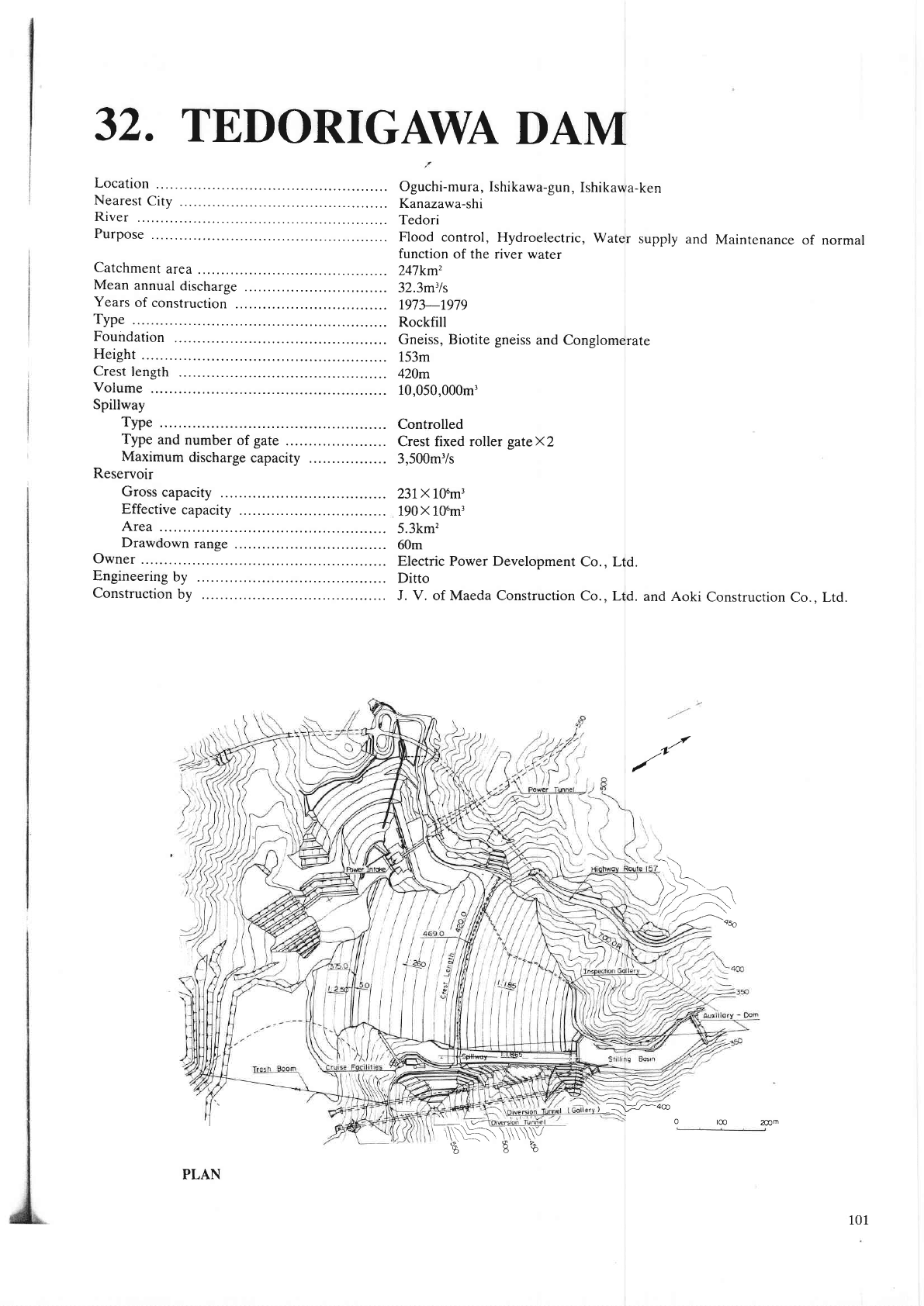
32.
TEDORIGNVA
DAM
Location
Nearest
City
.
River
Purpose
Catchment
area
Mean
annual
discharge
Years
of construction
.
Type
Foundation
Height
Crest
length
Volume
Spillway
Type
Type
and
number
of
gate
.
Maximum
discharge
capacity
Reservoir
Gross
capacity
Effective
capacity
Area
Drawdown
range
Owner
Engineering
by
Construction
by
Oguchi-mura,
Ishikawa-gun,
Ishikawa-ken
Kanazawa-shi
Tedori
Flood
control, Hydroelectric,
water
supply
and
Maintenance
of normal
function
of the river water
247km'
32.3m31s
r973-1979
Rockfill
Gneiss, Biotite
gneiss
and
Conglomerate
153m
420m
10,050,000m,
Controlled
Crest fixed rollet
gatexz
3,500m'/s
23IX 106m3
190X 10um'
5.3km'z
60m
Electric
Power
Development
Co., Ltd.
Ditto
J. V. of Maeda Construction
Co.. Ltd.
and Aoki
Construction
Co.. Ltd.
./
,i-
) >>
\
____-__..
'/rt
--t,
\
72,-;l)*
0
tm
2@m
101
PLAN
-. \
v
\!L!G!!j-SL!9]-!9
N)F\\\\\W
gB"$
l\:,'-4co
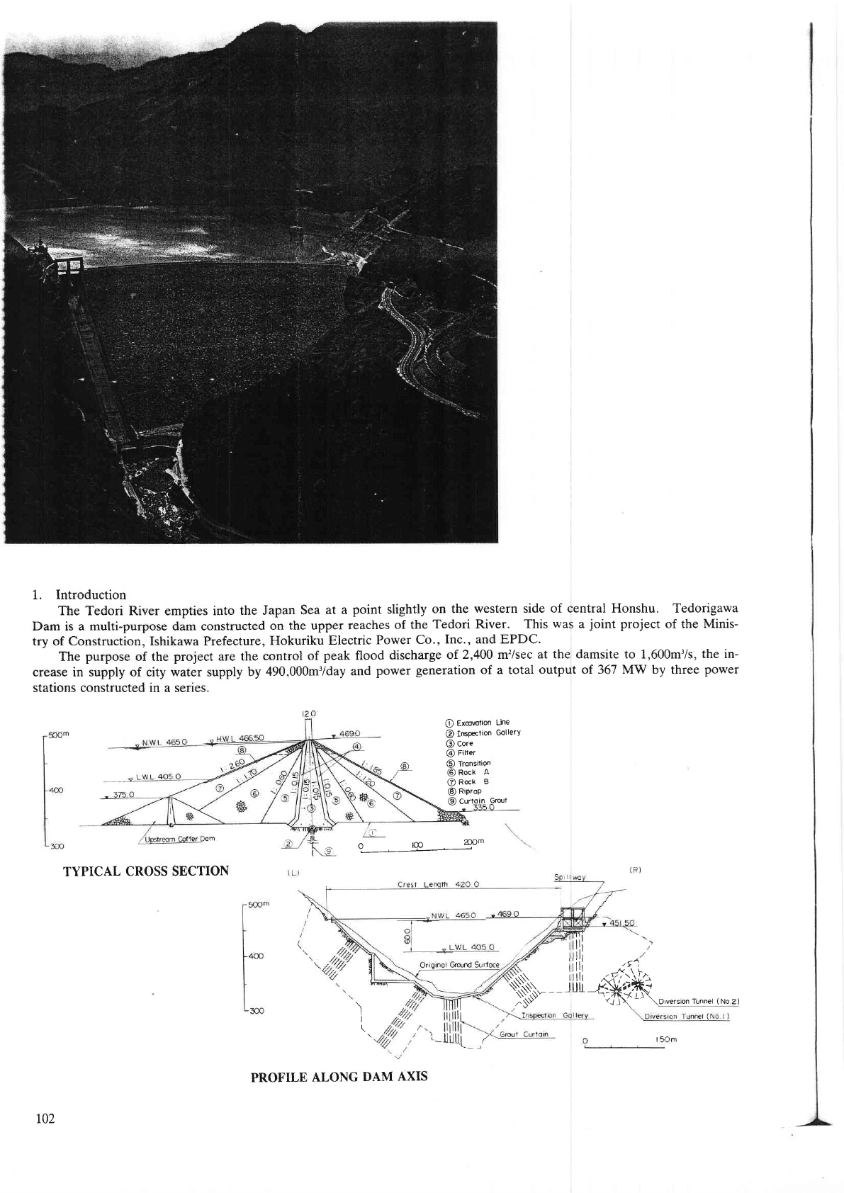
1. Introduction
The Tedori River
empties
into the Japan
Sea
at a
point
slightly
on
the westem side of central Honshu. Tedorigawa
Dam is a multi-purpose dam constucted
on the upper
reaches
of the
Tedori River. This
was
a
joint
Foject
of the
Minis-
try of Construction, Ishikawa Prcfecture,
Hokuriku
Electric
Power Co.,
Inc., and EPDC.
The
purpose
of the
project
are
the control
of
peak
flood
discharge
of 2,400 m'?/sec
at the damsite to 1,600m'/s, th€ in-
crease in supply of city water suppty by
490,000mr/day
and
power
geleration
of a total
output of 367 MW by three
power
stations constructed in a series.
O
Exco\€tion
Une
@
ImPection
GollerY
@
core
@
Fitter
O
Tronsition
@
Rock
A
@ncr
e
@
Riprop
@
curl-o1n
Gro:t
^ m
2OOm
w'?-
TYPICAL
CROSS SECTION
I
I
\
\\\
llllt
.*.5,;
NV__Jrr{,ffi
iiiil
"&;\h
\Drversion
Tunnel
(No
2)
t02
PROFILE
ALONG
DAM
AXIS
2.
Topography
and
Geology
The
width
of
the river
at the
damsite
is approximately
20m, with
the width
of
the
valley
bottom
approximately
60m,
while
the
average gradient
of the
slopes
of boih
banks
are about
40deg.
The
talus
deposits
on uotn
L'r'nr"
are generally
thin,
and
the
sand-gravel
deposit
on the
river-bed
is attout l5m
at
maximum.
Foundation
rock
of the damsite
consist
of Hida
gneiss
unconformably
underlain
by
Mesozoic
Gomishima
conglomerate
of
the
Tedori
Group.
.
The-.middle
and
upper parts
of the
right
abutment
consist
of conglomerate.
The
river
bed
and the
Ieft abutment
con-
sist
of Hida gneiss.
A fault exists
at midheight
of the
left abutment;hich
is
approximarely
25m
wide.
The
gneiss
and
the
limestone
at.the
river
bed
are
generally
hard
and
compact.
The
conglomeraies
of
the
right
uuutrn"ntlr"
hard,
but the
surface
part
is loosened
due
to creep
phenomena
creating
open fissures.'
3.
Construction
3__1.
Materials
Rock
material
was
conglomerate
from
a quarry
0.5km
upstream
of
the dam,
and
gneiss
of
the
dam,
and
because
the gneiss
was greatly
of weathered,
it was
decided
to
bank
it
in
glomerate
was
used
mainly
for
the
outer
zone.
from
a quarry
1.0km
upstream
the
inner
zone,
while
the
con-
damsite,
filter
was
obtained
directly
producedata
quarry
on the
left
banl
Since
river-bed
gravel
suitable
for filter
was
not
available
in
the
vicinity
of the
from
partially
weathered
rock
or from
selected
rock
material, while
material
was
also
upstream
of
the
dam.
Impervious
earth
core
material
was
mainly
talus
and weathered
rock.
For
the
reasons
below,
a
material
of coarse
gradation
to a
certain
extent
and
not having
an
excessively
high water
content
was
selected.
(1)
That
high
density
can
be obtained
stressing
strength
and-stability
since the
dam
is high.
(2)
That
construction
with
heavy equipment
can be
plrformed
in
oider
to hcrease
the rate
of embankmenr.
Although
it
would
have
been
ideal
for the
mate;ials
to be obtained
from
one borrow
area,
since
th"." *u,
no uor.o*
area
satisfying
the
Previously-mentioned
coriditions
as a result of
invesrigations,
material
were
taken
ftom seven
areas,
and
blended.
!-2.
Embankment
Embankment
of the dam was
started
from
December
1975
and completed
in
october
1g7g
with
the actual pedod
of
:T}g::ll
'z6
T"nths
excluding^
3
,months
of wintertime
suspension
every
year.
Perforrnance
during
this
period
was a
oally_maxrmum
ot
approximately
8,000m3
for
the core and
a daily
average
of approximately
2,g00m,,
w"hite
as a whole
the
monthly
maximum
was
905,000mr
and
the monthly
average
3g7,0d0m,.
Embankment
control
standards
were
established
aiter
carrying
out
test banking.
compaction
of
the core
was by
sheep's
foot
roller
fot
reason that the
contact
pressure
was high,
th;t
crushing
of
materials
could
be
counted
on, and that
permeability
would
be desirable.
The
filter was
to
rise roughly at
the
same elevation
as the
impervious
core, spreading
out
the materials
in
thickness
of 40cm.
The
compacting
methJd
ior
the rock
zone was
by
the
smooth-drum
vibratory
rollers.
Rock
matedal
spread
out
in thickness
of
60cm-150cm
was compacted
by 12
passes
of the
roller,
on
spreaoing
out ttre
materials
in thickness
of 20cm.
3_-3.
Foundationtreatment
-
The
curtain grouting
was
performed
by the
stage
grouting
method from inside
an inspection
gallery providing
a dif-
ferential
of approximately
20m with the
core embankment elevation,
the maximurn
deprh being
tSO.,
aoa the
giouting
pressure
5 to 30kgicm'.
The length
of drilling
performed
for
grouting
reached
approximately
80,000m.
Blanket
grouting
was
caried
out befor
the of core
embankment
ftom the surface by the stage
grouting
method
with
hole lengths of 20m, at
spacing
of 2.50m
over
the entire core width,
with
grouting pressures
3 to 2okg/cm':.
The drilling
had amounled
to approx-
imatety
62,000m.
Grouting
was
also
performed
to reduce
permeability
of a sheared
zone of
the fault in the left-
bank.
The
total
length of
gouting
was approximately
25,000m.
4. Measurements
In order
to
confirm
safety of the dam
and the foundation, earth
pressures,
pore
pressures,
settlement,
deformation of
the foundation,
and
deformation
of embankment were
measured
and
are continuing to
be measured.
The
pore
pressures
during
construction were
about 30Vo of
dead
weight at maximum,
for ample
safety compared with
the
design
value.
Settlement
of the dam
qest
was
44.3cm
(0.28%
ot dam height) in 1
year
8
months
after reaching normal water level,
while the
horizontal
movement was
a maximum ol 3.7cm
(O.OZV|
of
dam
height) and it
appears that elastic deformatior
was
occurring
in
accordance with
the dse and fall
of the
water level.
5. Power
Generating
Facilities
A maximum
of 180mr/sec
of water is
conducted
from
a
surface intake
gate
in an intake
structure
of 81m
high
Con-
structed
on
the left
bank of the dam.
After
passing
a surge tank and a
penstock
of
inside diameter
6.8m to 6.5m, the wa-
ter
is divided
into two
lines by a spherical
bifurcator of inside diameter of 9m.
Utilizing an effective head of 162.4m
at
a
semi-underground
powerhouse
constructed in
the left bank of
the
Tedori River approximately 2.4km
downstream ftom the
dam, a
maximum
of 250 MW is generated
by two turbines and
gereraton.
Water discharged ftom
the
powerhouse
is re-
leased into
the
Regulating
Pond of Tedofigawa
No.2
(Hokudku
Elect c Power Co.,
Inc.) hyroelectdc plant.
103
33. TERAT]CHI
DAM
Location
Nearest
City .
River
Purpose
Catchment
area
Mean
annual discharge
Years
of construction
.
Type
Foundation
Height
Crest length
Volume
Spillway
Type .-................
..... Controlled
Type and
number of
gate
...................... Crest
fixed roller
gateX2
and Orifice radial
gateXl
Maximum
discharge capacity .................
1,08ftn%
Reqervoir
Gross
capacity .......,..
18
X
10"m'
Effective capacity ...... 16x 1cl6ml
Area .................. ..... 0.9km'
Drawdown range ....... 38.5m
Owner ..............,.
...........
Water Resources
Development
Public Coryoration
Engineering
by .......,.......
Ditto
Construction ty .....................
J. V.
of Hazama-Gumi,
Ltd. and
Japan
Development
& Construction
Co
'
Ltd.
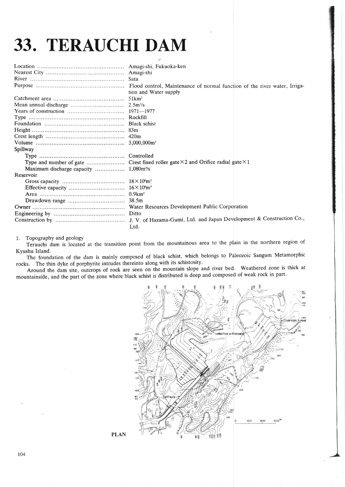
1.
Topography
and
geology
Terauchi
dam is located
at the
transition
point
from
the
mountainous
area
to the
plain
in
the northem
region
of
Kyushu Island.
The foundation of the
dam is
mainly
composed
of
black
schist,
which
belongs
to
Paleozoic Sangum
Metamorphic
rocks.
The thin dyke of
porphy
te
intrudes
thereinto
along
with its
schistosity'
Around the dam site,
outcrops
of rock
are
seen on
the
mountain
sloPe
and
river bed.
weatheled
zone is thick
at
mountainside.
and the
Dart
of
the zone
where black
schist
is
distdbuted
is deep
and composed
of
weak rock
in
part'
,
\rto
^
.roo
,t*
^\too
,/
tto
,/
Amagi-shi, Fukuoka-ken
Amagi-shi
Sata
Flood
control, Maintenance
of normal function
of the river
water,
Irriga-
tion and Water supply
51km'?
2.5m3ls
797r-r977
Rockfill
Black schist
83m
420m
3,000,000m,
104
PLAN
o
roo
no
3oom
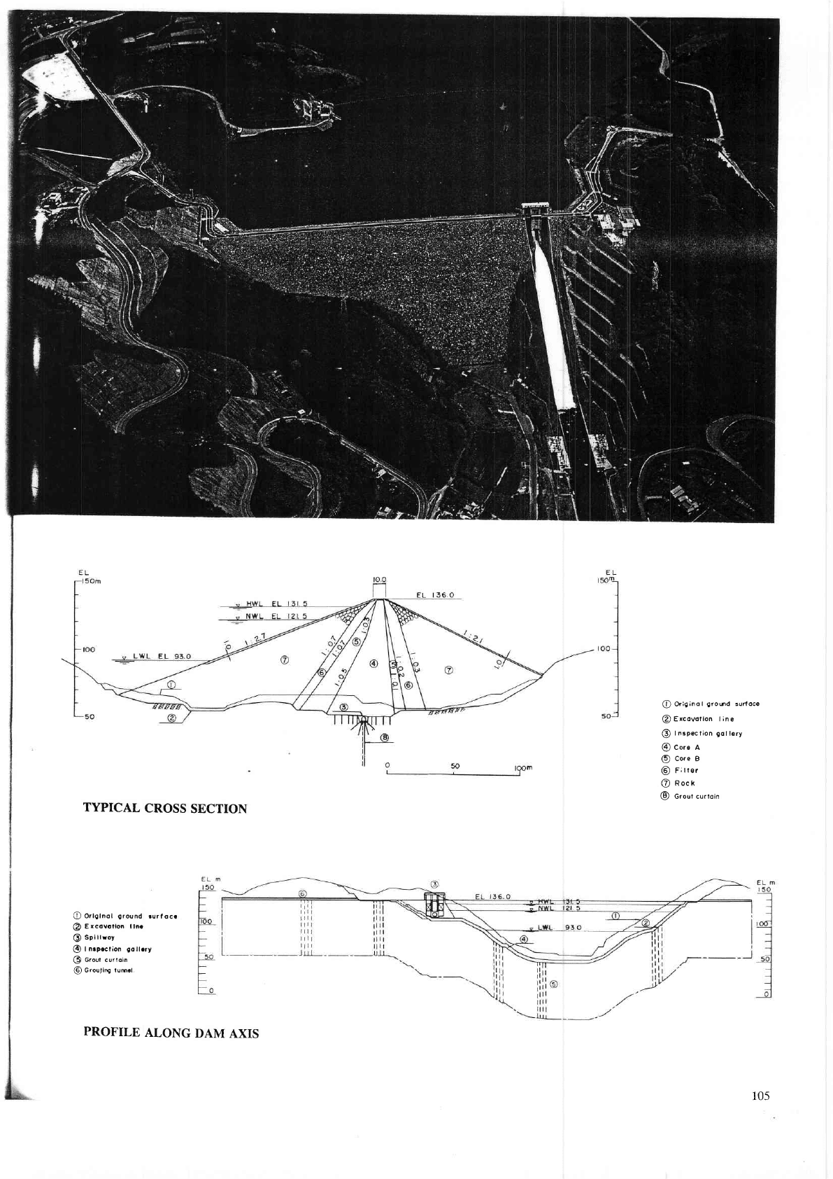
@
Or;9;no
t
gro0d
surf oca
@
Ercov6tlon t
ine
O
Inspection
gotl€ry
@
core n
@
Core
B
@
F;tter
@
nocr
@
Grout curtoin
TYPICAL
CROSS
SECTION
@
Ortgtnot
ground
rurfocr
@
Excovotlon lln.
@
sptttroy
@
|
nrpcction
gollrry
@
Grour curtoin
@
Grouring tum.t
105
PROFILE
ALONG
DAM
AXIS