Jan Svoboda. Magnetic Techniques for the Treatment of Materials
Подождите немного. Документ загружается.


330 CHAPTER 5. PRACTICAL ASPECTS OF MAGNETIC METHODS
Table 5.2: Comparison of dierent types of dry magnetic separators, as applied
to phosphate recovery (after Roux et al. [R19]).
Parameter IMR RE Roll HGMS OGMS
Capacity Low, 4
t/h/m
Low, 8
t/h/m
High, 400
t/h
High, 60 t/h
Power input 2kW/t 0.6 kWh/t 5.6 kWh/t 0.5 kWh/t
Ore distribution Complex Complex Simple Simple
Mass [kg] per t/h of
feed
2200 440 4100 41
Sensitivity to ore
variation
High Low Low Very high
Recovery of the fines Poor Very poor Good Very poor
Table 5.3: Comparison of IMR and RE roll in ilmenite-rutile separation (after
Arvidson [A26]).
Product IMR @ 2.5 t/m/h RE roll @ 4 t/h/m
Magnetics (mass %) 25 30.5
Non-mags in mags (%) 2.5 0.46
Middlings (%) 10 0.8
Non-magnetics (%) 65 68.7
Mags in non-mags (%) 0.5 0.28
velocity to the particles, thereby counteracting, to a considerable extent, the
sweeping across of non-magnetic particles by the magnetic ones. This approach
made it possible to obtain metallurgical results comparable with those of IMR
separators, at feed rates of up to 6 t/h per meter width, or 3.5 times the optimum
feed rate of an IMR.
Comparison of dry separators for beneficiation of beach sands and
other industrial minerals.
High-intensity magnetic separation has been a standard beneficiation method
for heavy mineral sands and various industrial minerals, and a variety of dry
magnetic separators has been used. With the advent of aordable rare-earth
permanent magnets, and as a result of design improvements, the conventional
dry separators, such as induced magnetic roll and cross-belt separators are be-
ing replaced by reliable and economical rare-earth roll and drum separators
[A24, A25, A26]. Although the plant data are usually confidential, comparative
studies indicate superior performance of the rare-earth-based separators. An
example is shown in Table 5.3, which compares the separation e!ciency of IMR
and RE roll separators as applied to ilmenite and rutile separation.
A similar improvement in the e!ciency of separation after replacing the in-
duced magnetic roll with a permanent magnetic roll, was obtained with feldspar.

5.2. DRY MAGNETIC SEPARATION 331
Table 5.4: Comparison of IMR and RE roll magnetic separation as applied to
beneficiation of feldspar [A24].
Product IMR RE Roll
Magnetic fraction 12% - 14% 4% - 4.5%
Non-magnetic fraction 86% - 88% 95.5% - 96%
Table 5.5: Reduction of the iron content in various size fractions of feldspar, by
IMR and roll permanent magnetic separators. IMR was operated at
1.8 T [A27].
Separator Fraction [m] Fe oxides
in feed [%]
Yield into
non-mags
[%]
Fe oxides in
non-mags
[%]
IMR - 500 + 212 0.20 95.5 0.04
- 212 + 106 0.43 93.0 0.06
- 106 + 74 0.45 82.3 0.07
Roll - 500 + 212 0.20 86.6 0.08
- 212 + 106 0.43 85.8 0.10
- 106 + 74 0.45 79.5 0.11
This is shown in Table 5.4. On the other hand, results of another comparative
study [A27], summarized in Table 5.5, indicate a superior performance of an
induced magnetic roll, in the entire range of particle sizes.
Dry magnetic separators can also be e!ciently used to recover metal from
slags. Comparison of several dry separation techniques to recover ferrochrome
from coarse slag is shown in Table 5.6 [S58].
A dry ferrite roll separator was also successfully applied to the recovery of
the ferrochrome metallics from a fine fraction (- 0.8 mm) of slag. Comparison
of its performance with a wet rare-earth drum separator is shown in Table 5.7.
Replacement of conventional electromagnet-based separators by rare-earth
permanent magnet units also often results in economic advantages. Improved
quality of the ilmenite concentrate and reduced operating costs contribute to
improved plant e!ciency, as shown in Table 5.8. Additional cost savings result
Table 5.6: Recovery of ferrochrome metal from slag (- 15 + 2 mm) by magnetic
separation [S58].
Separator Head grade
[FeCr%]
Mags grade
[FeCr%]
Recovery [%]
Dry LIMS 22.7 60.6 85.0
Lifting IMR 20.1 77.6 85.8
Ferrite roll 27.1 45.7 97.5

332 CHAPTER 5. PRACTICAL ASPECTS OF MAGNETIC METHODS
Table 5.7: Recovery of ferrochrome metal from fine slag (- 0.8 mm) by magnetic
separation [S58].
Separator Head grade
[FeCr%]
Mags grade
[FeCr%]
Recovery [%]
Ferrite roll 4.4 16.9 65.6
Wet RE drum 4.7 17.3 70.2
Table 5.8: Comparison of the operating costs of various dry magnetic separators
applied to ilmenite beneficiation, in relation to a cross-belt separator
[A24].
Magnetic separator Cost
Cross-belt 100
IMR 42 to 53
RE drum separator 17
RE roll (short belt life) 21 to 42
RE roll (long belt life) 11 to 15
from a smaller size of the plant for a given throughput. Since a plant with
rare-earth magnetic separators would use between 6% and 20% of a cross-belt
plant space [A24], the cost saving can be considerable. Compared to IMR for
non-magnetic cleaning applications, the space saving can be 50% to 70% [A24].
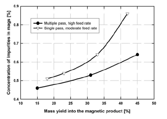
Improved performance can be also obtained by implementing multiple-stage
separation, as is demonstrated in Fig. 5.7. Combined with higher roll speeds,
the selectivity of separation increases in addition to a higher throughput.
In some applications, it was found advantageous to combine rare-earth roll
separators with rare-earth drum separators. While roll separators tend to be
more e!cient, more selective and can be more readily adjusted to feed variations,
drum separators have a higher throughput and are less demanding from the
maintenance point of view. Comparison of the roll and roll+drum options is
shown in Table 5.9.
Table 5.9: Comparison of roll and roll+drum alternatives for treatment of il-
menite gravity concentrate (- 0.9 + 0.1 mm), at 30 t/h, in 1999
prices [A25].
Parameter Drum + Roll Roll separator only
Stages required 1 drum + 2 rolls 3 stages
Capacity 7 t/h/m 4 t/h/m
Quantity 3 5
Price per unit [US$] $114 000.00 $65 000.00
Total price [US$] $342 000.00 $325 000.00
5.2. DRY MAGNETIC SEPARATION 333
Figure 5.7: Comparison of single and multiple-pass separation of ilmenite, by a
roll separator, at dierent feed rates (adapted from Arvidson [A26]).
Comparison of roll and matrix separators
Jirestig and Forssberg [J7] carried out a detailed comparative study of four dry
high-intensity magnetic separators. Three of these separators were roll units:
Permroll
R
°
(E.L. Bateman) with Kevlar belt, High Force
R
°
(Inprosys) with
polyurethane belt, induced magnetic roll (Humboldt Wedag) and dry HGMS
(Sala). An expanded metal matrix, with and without spacers, was used in the
Sala HGMS and particles were propelled through the matrix by a compressed
air-driven vacuum pump. Various size fractions of calcite and dolomite samples
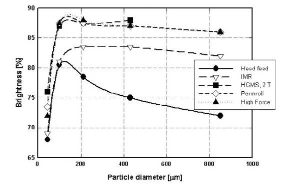
were used as test materials. Permroll, High force and dry HGMS, operating at
2 T yielded products of similar brightness for fine to medium-size (- 450 + 38
m) particles, as can be seen in Fig. 5.8. For particles larger than 450 m,
the Sala HGMS machine experienced problems with matrix clogging, while the
e!ciency of the induced magnetic roll was slightly inferior.
The significant advantage of the matrix separator, compared to belt-type
separators, is its high selectivity of separation of fine particles, smaller than 100
m. The high brightness of products from belt separators was achieved at great
cost to the recovery. Only about 5% of 38 m material reported to the mag-
netic fraction in the matrix separator, while Permroll and High Force machines
experienced significant losses (35% to 80 %) of the valuable material into the
magnetic tailings. The dierent performances of the two belt separators are
probably due to dierent types of belts used and the results indicate the impor-
tance of controlling electrostatic properties of the belt material, as discussed in
Section 5.2.1.
334 CHAPTER 5. PRACTICAL ASPECTS OF MAGNETIC METHODS
Figure 5.8: Brightness of various size fractions of the calcite non-magnetic prod-
uct, as obtained in several dry magnetic separators (adapted from
Jirestig and Forssberg [J7]).
Comparison of rolls of dierent diameters
Magnetic rolls of diameter ranging from 72 mm to 300 mm are commercially
available and judicious selection of the most suitable unit is essential for opti-
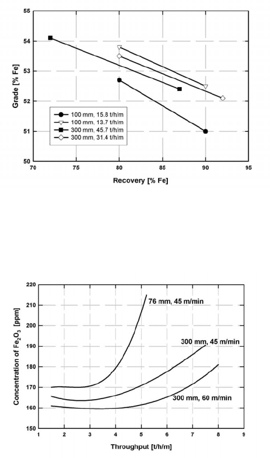
mum metallurgical results and operating costs. Figures 5.9 and 5.10 illustrate
that magnetic rolls of larger diameter (300 mm) can operate at higher feed
rates than standard 76 and 100 mm diameter rolls. By increasing the speed
of rotation the same performance can be maintained. As has been discussed
in Section 4.6.2, the magnetic force is practically independent of the magnetic
ring diameter. The increase in the rotational speed of the roll, maintaining the
same residence time of particles in the magnetic field as in a smaller diameter
roll, results in the increase of the centrifugal force on a particle. In turn, this
results in a closer balance of the magnetic and competing forces and better se-
lectivity of separation can thus be obtained. This additional benefit of larger
ring diameters is depicted in Fig. 5.10.
Comparison of RE roll and RE drum separators
Rare-earth roll separators and rare-earth drum separators are designed to ad-
dress similar beneficiation applications. The choice between these two types
of separators is rarely made on the basis of comprehensive comparative tests.
Since the pattern of the magnetic force around the roll and drum dier consid-
erably, correct systematic evaluation of the operation is essential. As has been
discussed in Section 4.6.2, magnetic roll separators generate a much higher mag-
5.2. DRY MAGNETIC SEPARATION 335
Figure 5.9: Comparison of separation e!ciencies of magnetic rolls of diameters
100 and 300 mm, at dierent throughputs, as applied to beneficiation
of - 3 mm iron ore (adapted from Arvidson and Dillé [A23]).
Figure 5.10: Comparison of performances of 76 mm and 300 mm rolls at dierent
speeds of rotation, applied to purification of - 600 + 800 mm silica
sand (adapted from Dobney [D8]).
336 CHAPTER 5. PRACTICAL ASPECTS OF MAGNETIC METHODS
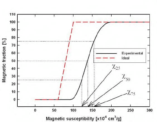
Figure 5.11: Magnetic partition curves. The ideal curve corresponds to a mag-
netic susceptibility cut-point of "
50
=80×10
6
cm
3
/g (10×10
7
m
3
/kg) [M24].
netic force, which, however, is of short reach. On the other hand, the magnetic
force on the surface of a drum separator is much lower, as a result of a con-
siderably lower magnetic field gradient. The reach of the force is, however,
much longer than that in a roll separator. The behaviour of particles in these
two types of separator is dierent and the settings of the optimum operating
conditions dier widely.
Detailed comparative tests on rare earth roll and drum separators were con-
ducted by Murariu and Svoboda [M24]. Magnetic tracers of various sizes and
mass magnetic susceptibilities were used to set the optimum operating condi-
tions, and magnetic partition curves were generated. The values of Hs, given by
eq. (4.58), of these curves were compared. Figure 5.11 illustrates such a parti-
tion curve for the cut-point magnetic susceptibility of 80×10
6
cm
3
/g (10×10
7
m
3
/kg). The cut-point is defined as the value of magnetic susceptibility ("
50
),
for which the particles having this susceptibility split equally into the magnetic
and non-magnetic fractions.
It was observed that the same cut point could be obtained using dierent
combinations of the speed of rotation of the drum or roll and of the position of
the splitter. However, not all combinations of these parameters give the same
optimum e!ciency of separation, as is demonstrated by Fig. 5.12. It can be seen
that, for a drum separator, a lower speed and a closer position of the splitter
between the magnetic and non-magnetic fractions, result in lower Hs and thus
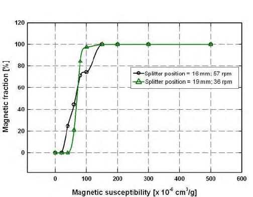
5.2. DRY MAGNETIC SEPARATION 337
Figure 5.12: Experimental partition curves for an NdFeB drum magnetic sep-
arator. The curves were obtained for the same value of the cut
point, but for dierent positions of the splitter and the rotational
speed of the drum. Drum diameter: 600 mm, magnetic induction
on the drum surface: 0.9 T [M24].
amoree!cient separation.
However, with a roll separator (diameter 100 mm), a more selective separa-
tion was achieved at a high roll speed and with a splitter far from the roll. This
dierence in the optimum operations of drum and roll magnetic separators re-
sults from the fact that the magnitude of the magnetic force acting on a particle
in a drum is much smaller than that in a roll separator. As discussed in Section
1.2, the separation is selective when the magnitudes of the magnetic force and
the competing forces are of comparable magnitudes. The magnetic roll, which
generates a higher magnetic force than the drum, requires a higher centrifugal
force (i.e. a higher roll speed) and a more distant position of the splitter.
Tracer tests showed that the setting of the cut point, that is of the rotation
speed of the roll or drum and position of the splitter, is dependent on particle
size. The size dependence was found to be approximately linear for both separa-
tors, as is illustrated in Fig. 5.13. The slope of the plots indicates sensitivity of a
separator to the size of the tracers. It can be seen that roll magnetic separators
are considerably more sensitive to particle size and the sensitivity increases with
decreasing thicknesses of the magnet and steel rings. A roll separator of a given
configuration is, therefore, suitable for accurate separation of only a narrow size
range of the feed particles. For example, if the cut point is set to 10×10
7
m
3
/kg
(80×10
6
cm
3
/g) and the required accuracy is ± 10% (two horizontal lines in
Fig. 5.13), a roll separator with configuration 12/7.5 will satisfy the accuracy
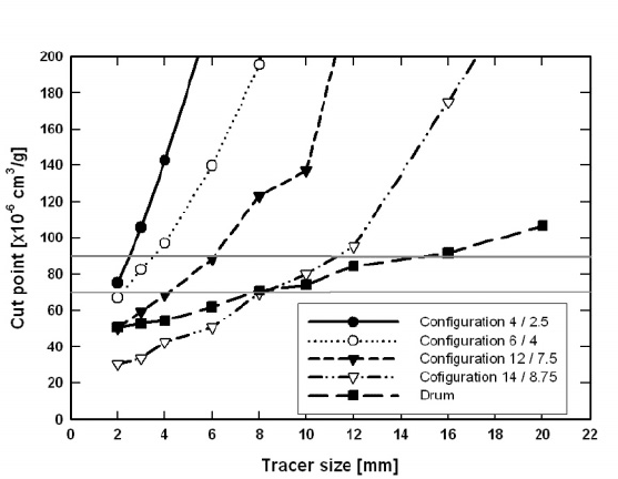
338 CHAPTER 5. PRACTICAL ASPECTS OF MAGNETIC METHODS
Figure 5.13: Variation of the cut-point magnetic susceptibility with the size of
magnetic tracers, for roll and drum magnetic separators of dierent
configurations [M24].
requirement for a size fraction - 6 + 4 mm. A roll separator with configuration
4/2.5 will meet this requirement only for particle size of 2 mm. On the other
hand, the drum separator will be able to treat selectively a size fraction of - 16
+8mm.
The loading of the belt or the drum The loading of the drum and of
the belt of the roll separator, influences the throughput and the e!ciency of
separation, and a compromise must be found between these two contradictory
requirements. As a result of a short residence time of particles on the roll surface,
the feed material must be distributed evenly over the belt in a monolayer and
a safe belt loading is approximately 25%. Lower belt loadings lead to a low
throughput and generally cannot be justified in view of a limited benefit and
high cost of the separator.
In drum separators, the residence time is much longer and if the feeding
system is optimized and the feeder tray is su!ciently close to the drum, to
avoid particle bouncing, the particles usually spread evenly on the drum surface
even when particles flow in a thicker layer on the feeder tray. Typical flow
of material onto a drum surface is shown in Figs. 5.14 and 5.15. However,
adherence of strongly magnetic particles on the drum surface can be a problem,
as shown in Fig. 5.16.
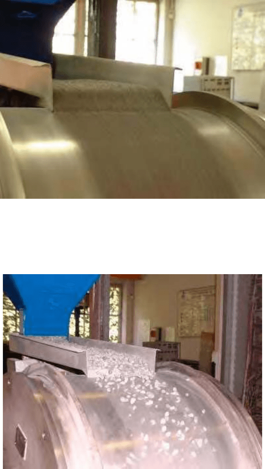
5.2. DRY MAGNETIC SEPARATION 339
Figure 5.14: Flow of the - 2 + 1 mm material on the surface of an NdFeB drum
magnetic separator.
Figure 5.15: Flow of the - 16 + 8 mm material on the surface of an NdFeB drum
magnetic separator.