Hughes M.P., Hoettges K.F. (Eds.) Microengineering in Biotechnology
Подождите немного. Документ загружается.

is the material of choice for many micromoulding applications. It is
inexpensive, biocompatible and transparent, making it ideal for use
in many biochemical applications. PDMS also has excellent sealing
properties both to glass and also to itself, the latter allowing for the
fabrication of complex multilayered fluidic structures (49). Typi-
cally, a mould (commonly known as a ‘‘master’’) is produced using
one of the hard micromachining technologies described above
(depending on the material, surface treatment of the master may
be required to facilitate delamination of the cured PDMS from the
master). The PDMS prepolymer (mixture of the PDMS linear
polymer and a cross-linking agent) is mixed and then poured
onto the mould and left to cure. Once the polymerisation is
complete, the cured PDMS is peeled off the master and can be
bonded to a solid substrate (e.g. glass) or another piece of cured
PDMS to form the fluidic channel. Surface treatment of the
PDMS is possible, allowing one to change its wetting properties
(from hydrophobic to hydrophilic), as well as other surface func-
tionalisation techniques (50, 51). A number of review articles by
Whitesides and others are available (48–50).
3.2.2.2. Hot Embossing Polycarbonate and PMMA are the most widely used polymers for
embossing (45, 52, 53). A stamp (master) is brought into contact
with the polymer surface. An even pressure is applied and the
polymer substrate is heated above its glass transition temperature,
the polymer flows taking up the profile of the master. The sub-
strate is cooled and removed from the stamp. This technique can
be used to produce micro- and nanoscale features and is described
as micro- or nanoimprint lithography (54). As well as microfluidic
channels, embossing has been used to fabricate a number of optical
components such as microlenses, diffraction gratings and wave-
guides (55, 56).
3.2.3. In Situ Construction The incorporation of hydrogels and other similar polymers into
microfluidic channels is a recent development (67–60). The inte-
gration of such active polymers with other micromachined and
soft materials allows for the implementation of environmentally
(i.e. within the microfluidic channel) responsive functionalities
that are difficult to realise otherwise. Work has shown the use of
polymers that react by swelling in response to changes in the local
environment of the fluidic channel. Hydrogels sensitive to pH,
temperature, conductivity, light, glucose level, etc., have been
demonstrated, and applications include their use in ‘‘smart’’ on-
chip fluid flow control (57–61).
3.3. Other Methods A number of other technologies have been explored within the
literature. Microstereolithography is a technique allowing the fab-
rication of three-dimensional structures; it relies on the photo-
polymerisation of liquid polymers using a focused beam of UV
The Application of Microfluidics in Biology 65

light (62). Powder blasting has been used to fabricate channels
with dimensions down to 50 mm; this technique is limited by the
rather rough channel surfaces created, resulting in difficulties in
observation (63).
A number of examples of channel-free microfluidic devices
have been presented; these can generally be described as dro-
plet-based microfluidics, where the sample volume is confined
within droplets formed in two-phase systems (typically such
experiments are carried out in water-in-oil or vice versa to
reduce the effect of evaporation). Examples can be found in
electrowetting technologies (64, 65) and droplet-based chemi-
cal reactors (66).
3.4. Biocompatibility Surface chemistry is of great importance in microfluidic systems
due to the extremely high surface area to volume ratio, with non-
specific adsorption of sample to the channel walls resulting
in channel blocking and disruption of the fluid flow (especially
in electrokinetic-based flow devices). As described above, silicon
does not generally lend itself to chemical modification and there-
fore is limited in its utility. Glass and various polymers have good
properties and are widely used, with polymers generally being
preferable due to their reduced cost over glass. PDMS has the
highly desirable property of being gas permeable, thus making it
suitable for cell culture applications. For a recent review on
biocompatibility in microsystems the reader is referred to the
literature (67).
4. Applications
We will now look at some examples of microdevices used in
biology. The selection of devices represents a diverse range of
applications, but is by no means exhaustive in its coverage.
4.1. Cellular
Manipulation
and Analysis
A number of on-chip cell detection and handling techniques have
been demonstrated in the literature. Examples include cell culture
devices, electroporation and lysis chips and microfabricated flow
cytometers. Working with small numbers of cells also becomes
possible and recently a number of single-cell devices have been
developed.
4.1.1. Cell Culture Devices Studies of drug effects, osmotic balance, cytogenic and immuno-
logic responses and metabolism have all been carried out using
microfabricated cell culture devices (68). The first human embryo-
nic stem cell culture in a microfluidic channel was recently reported
by Abhyankar et al. (69). Integrated chips with embedded fluidic
66 Holmes and Gawad
channels for nutrient delivery were reported by Heuschkel et al.
(70). A number of systems demonstrating the possibility of
long-term cell culture in microfluidic networks have been
reported, and the effects of nutrient levels and oxygenation (71).
Chin et al. (72) demonstrated a massively parallel single cell array
consisting of 10,000 microwells, all of which were exposed to the
same media. Over 3,000 individual rat neural stem cells were
cultured simultaneously. The cells were able to draw signalling
factors released from neighbouring cells within the device and
were also able to maintain paracrine signalling throughout experi-
mentation. Single cells were shown to survive and proliferate,
demonstrating the importance of intercellular signalling on cell
viability. Microfluidic devices capable of long-term culture of
multiple isolated cells, separated in individual wells, have obvious
application in drug testing or cell growth analysis (73, 74).
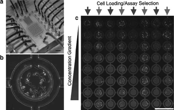
Figure 2.3 shows a multiplexed cell culturing device as
reported by Lee et al. (73). An addressable 8 8 array of 3-nL
chambers was fabricated and used to observe the serum response of
HeLa cells in 64 parallel cultures. The device is capable of produ-
cing concentration gradients along the length of the device and
individual rows are separately addressable.
Using photo-thermal etching of agar, it is possible to modify
the culture chamber geometry during culture. Studies have
demonstrated that it is possible to construct dynamic 3D networks
of cells, with no adverse effects on the cells under culture (75).
Fig. 2.3. (a) Micro cell culture device with a concentration gradient generator. (b) HeLa
cells cultured in a single well of the array; the central growth area has a total volume of 3
nL. (c) Fluorescence image of the array after 5 days of culture (73). (Reproduced with
permission from John Wiley & Sons, Inc.)
The Application of Microfluidics in Biology 67
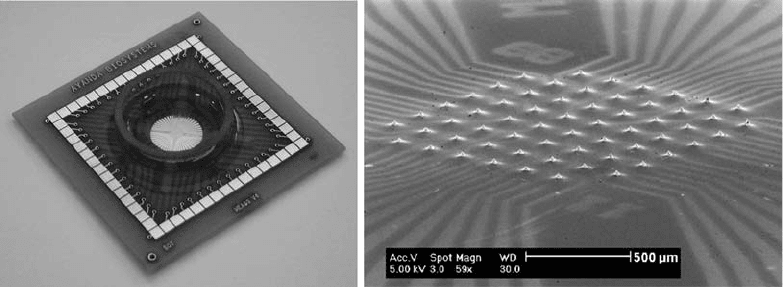
The inclusion of microelectrode arrays (MEA) in the base of
cell culture chips allows for the electrical recording and stimulation
of the cells under culture. Figure 2.4 shows an example of such a
device. Measurements of the localized electrical signals from neu-
rons and cardiac cells have been performed with application to the
study of drug effects on ion channels (76–78). The possibility of
culturing cells on multiparametric integrated sensors on silicon
was demonstrated by Brischwein et al. (79).
A number of systems for studying the effect of drugs on cells
have been developed. Tools for cell docking and capture have been
used in conjunction with controlled drug application and concen-
tration gradients (80). Patterned self-assembled monolayers
(SAMs) are also used to control cell surface topology and mole-
cular structure. Whitesides’ group used these techniques to help
understand the interaction of man-made surfaces with cells and
proteins (81) and for the study of cell conformation, attachment
and function (82).
Laminar flow can easily be used to create spatially and tempo-
rally varying microenvironments within the cell culture device.
Takayama et al. (83, 84) adhered a single bovine capillary endothe-
lial (BCE) cell in a microfluidic channel and flowed Trypsin/
EDTA locally over it and observed the detachment of the treated
area of the cell from the channel floor. The simple microfluidic
device consisted of three inlets from which the flows converged
into a rectangular capillary as parallel laminar streams. Different
fluorescent dyes were flowed over opposite sides of a live cell,
staining two subpopulations of mitochondria for observation.
The cell was locally treated with latrunculin A and the mitochon-
drial response to the cellular damage was observed.
Fig. 2.4. (a) Picture of the packaged MEA culture device. (b) SEM of a MEA showing the 60 tip-shaped protruding platinum
electrodes. A thin layer of polymer is used to insulate the electrode tracks so that only the tips are exposed for recording
and stimulation. (Images courtesy of M. Heuschkel, Ayanda Biosystems, Switzerland.)
68 Holmes and Gawad
4.1.2. Electroporation
and Cell Lysis
Electroporation exposes cells to electrical pulses of high intensity
(10
6
Vm
–1
) and of short duration (10
–3
–10
–6
s), causing a tempor-
ary increase of the cell membrane permeability. This leads to ion
leakage, escape of metabolites and increased uptake of drugs, mole-
cular probes, DNA, etc. (85). Applications of electroporation
include the introduction of plasmids or foreign DNA into living
cells for transfection and the insertion of proteins into cell mem-
branes. Generally performed in large vessels, this technique suffers
from a relatively low efficiency due to that fact that all cells are
exposed to the same electric fields. On-chip electroporation has
been demonstrated (86, 87). The application of nanosecond pulsed
electric fields (nsPEF), with high intensity and low energy, to single
cells allows the targeting of intracellular membranes and has been
shown to induce a number of cellular apoptotic or non-apoptotic
functions without directly harming the plasma membrane (88).
Single-cell electroporation is easily achievable in microfluidic
devices and permits the tuning of the applied electric pulse for the
individual cell according to its size and other electrical parameters,
giving more accurate control of the transmembrane voltage. The
composition of the medium directly around the cell is of prime
importance and can be closely controlled during the electroporation
process and pore opening time. For instance, the influx of Ca
2+
into
the cell should be kept low. Reactive oxygen species (ROS) liberated
by the cell during the electroporation process also impact on the cell
survival rate. Microfluidic studies have demonstrated that ascorbate
(a ROS scavenger) can reduce the cellular damage induced by ROS
and increase cell survival rate up to 50% (89).
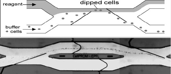
Cell dipping and washing using controlled fluid flow and nDEP
was recently demonstrated on a chip (Fig. 2.5) (90). Cells flow into
the main channel of the device from one of the inlet channels. The
reagent of interest is flowed in through a second inlet and flows side
by side with the cell sample in the channel. Electrodes on the walls of
Fig. 2.5. (a) Schematic of cell flow dipping in a microchannel. (b) RBCs suspended in PBS
are deviated laterally into an adjacent stream. After a short exposure to the other stream,
the cells are brought back into the PBS stream. (Images courtesy of Nicolas Demierre
and Urban Seger.)
The Application of Microfluidics in Biology 69
the flow channel guide the cells across the channel into and out of
the reagent stream. Flow ratios and speeds are set such that no dye
contaminates the cell outlet and to permit nDEP cell manipulation.
Varying the flow rate allows control of the incubation time of the
cells in the reagent under study. Very rapid reaction and washing
cycles are possible with such a device.
4.1.2.1. Cell Lysis Cell lysis is a preliminary step in the analysis and separation of
intracellular components such as DNA and proteins. Lytic agents
such as detergents or pure water are used to rupture the cell
membrane. A change in the tonicity of the suspension medium is
typically used to lyse erythrocytes and produce ghosts (spherical
emptied RBCs), which can then be resealed. On-chip electrolysis
has been demonstrated and can be performed in a timely, selective
and localized manner with reduced risk of damage or alteration of
the cellular content before separation (91, 92). Single-cell enzy-
matic lysis and identification of b-galactosidase activity have been
demonstrated (93).
4.1.3. Microflow Cytometry For single-cell optical measurement and sorting, the fluorescence-
activated cell sorter (FACS) offers a broad range of possibilities
(94). Flow cytometry allows the simultaneous measurement of
multi-colour fluorescence and light scattering from individual
cells as they rapidly pass through one or more focused laser
beams. Light absorption and scattering can be used to determine
relative cell size, shape, density, granularity of a particle as well as
stain uptake due to labelling with fluorescent probes. Modern
benchtop flow cytometers allow high-speed analysis and cell sort-
ing, with sort rates in excess of 10,000 cells per second possible
with modern machines.
It has been recently pointed out that even for high-end
versions of commercially available FACS instruments, forward
scattering signals of a mixture of size-calibrated beads is strongly
non-monotonic with particle volume (96). This issue seems to be
completely ignored by most FACS users, who are generally inter-
ested in broadly positive or negative fluorescence decisions.
The major drawbacks that currently limit the widespread
use of FACS systems are the high cost, complexity and size of
the instruments. To this end, a number of groups have been
developing microfabricated flow cytometers. On-chip optical
detection of single cells using forward scatter or fluorescence
signal has been demonstrated. Some of these systems have also
integrated sorting functionality, although at much reduced
rates compared with commercial instruments. Rare-event cell
sorting in a microfluidic system was suggested as a safer alter-
native method for the enrichment of prenatal nucleated RBC
from maternal blood (97).
70 Holmes and Gawad
Early results obtained using a microfluidic-based haematology
analyzer using small-angle scattering information from hydrodyna-
mically focused leukocytes showed possible differentiation of leu-
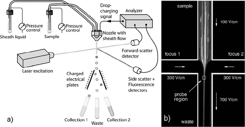
kocytes (98). Schrum et al. presented a microchip flow cytometer
that uses electrokinetically generated sheath flows as an alternative
way to achieve particle focusing (Fig. 2.6) (95). A microfabricated
fluorescence-activated cell sorter that can achieve rates up to 20
cellss
–1
was demonstrated by Fu et al., based on a fast forward–
backward electrokinetic flow switching procedure in a T-shaped
channel structure (99). A microfluidic device for fluorescence-
activated cell sorting that incorporates integrated light sources,
sensors and micro-optical components was discussed by Kruger
et al. (100). Measurement of the intrinsic autofluorescence signal
of single cells on chip showed measurable differences in the fluor-
escence levels between erythrocytes and granulocytes (101).
Optical tweezers using tightly focused laser beams provide a
tool for the manipulation of single micron-sized particles (102).
The technique is commonly used in microchips to capture beads,
cells and DNA (103). Complete integration of such a system into a
portable unit presents some issues (laser power source, movable
optics, etc.). DEP techniques are often favoured for control of
particle trajectories within the flow. Moreover, simultaneous
Fig. 2.6. (a) Schematic of a fluorescence-activated cell sorter. (b) Time-integrated CCD image of electrokinetically
focused 1.88 mm labelled particles on microchip. The exposure time was 5 s with sample and focusing field strengths of
100 V cm
–1
and 300 V cm
–1
, respectively. Arrows depict the direction of fluid transport and their lengths are proportional
to average fluid velocities in each channel. (Figure (b) reproduced with permission from Schrum et al. (95), ª 1999
American Chemical Society.)
The Application of Microfluidics in Biology 71
manipulation of multiple objects using the laser tweezer technique
is difficult. However, newly developed holographically generated
optical traps have demonstrated the possibility of generating mul-
tiple optical traps in three dimensions (104).
The first mCoulter devices were presented by Larsen et al.
(105) and Koch et al. (106, 107). These systems were microfabri-
cated in silicon and use microfluidic sheath flows and filter struc-
tures. These devices allow the measurement of the electrical
properties of individual particles as they flow through a micro-
channel. Reports of more sophisticated on-chip impedance mea-
surement devices were published later by Fuller et al., who looked
at granulocytes (108), Larsen et al. studied somatic cells using a
simple silicon aperture (109) and Gawad et al. used a coplanar and
facing electrode geometry to measure the properties of erythro-
cytes (110). More recently, Benazzi et al. investigated the proper-
ties of different species of marine algae; this work also
implemented optical detection in the same device allowing corre-
lation between the fluorescence of individual algae and their impe-
dance properties (111). The original mCoulter technique is clearly
limited to cell sizing by the use of a single measurement frequency,
generally at low frequency or DC. Measurement at multiple fre-
quencies is necessary to determine other attributes of the cell,
similar to what is obtained in traditional dielectric spectroscopy.
Microfabricated broadband single-cell dielectric spectroscopy
chips have recently been developed by the current authors (112)
and other groups (108). These are capable of performing high-
throughput analysis of the electrical properties of single cells and
other organisms. Details of this work can be found in Chapter 7
(Gawad et al.) within this volume.
4.1.4. Cell Sorting A number of on-chip cell-sorting devices have been described in the
literature. Quake et al. demonstrated a PDMS-based FACS capable
of sorting bacteria, DNA and other particles into two outlet chan-
nels based on the measured fluorescence of the particle (104).
A number of other groups used similar devices based on the switch-
ing of fluid flows between outlet channels using electrokinetic flow.
Holmes et al. (113) demonstrated devices for high-speed
analysis and sorting of individual cells and polymer beads based
on their optical properties. The device used nDEP to focus the
particles onto the central flow axis of the channel as they flowed
through the device. They obtained results similar to that of com-
mercial FACS, although at reduced particle throughput (100 s of
particles per minute). An arrangement of electrodes at the channel
junction is used to allow fast sorting of particles into one of two
outlets, using nDEP. Fluorescently labelled beads demonstrate the
system’s performance. Similar work was carried out on samples of
blood cells, bacteria and algae. A number of other DEP-based
particle sorting devices have been reported (7, 27, 114–116).
72 Holmes and Gawad
4.2. Macromolecules The area of micro total analysis systems that has seen the largest
number of applications is that of molecular separation, in particular
the separation and analysis of subcellular components such as
proteins and DNA. On-chip separation techniques making use of
electrophoresis include capillary electrochromatography (CEC)
(117), which typically employs microbeads packed in the capillary
channel. Isoelectric focusing (IEF) is a commonly used technique,
whereby a molecular-specific isoelectric equilibrium point
is reached in a pH gradient (118, 119). Dielectrophoresis is widely
used to separate proteins, DNA, viruses and other bio-
nanoparticles (19).
4.2.1. DNA
4.2.1.1. PCR
One of the most common methods for analysing DNA and
proteins is capillary electrophoresis (CE). In the case of DNA
it is generally preceded by an amplification technique: the poly-
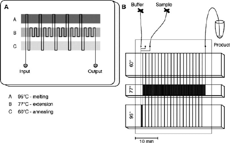
merase chain reaction (120). Figure 2.7 illustrates an example
of an on-chip PCR device; a serpentine channel was fabricated
to flow across three heater elements with temperatures of 95C,
77Cand60C. The flow rate, length of the channel and
serpentine geometry define the duration, rate and number of
heating cycles that the sample undergoes. Microdevices that
intergrate cell lysing, PCR and CE functionalities have been
demonstrated (121).
Fig. 2.7. Continuous-flow PCR on-a-chip. (a) Schematic of chip layout; (b) schematic of experimental set-up. (Reproduced
with permission from Kopp et al. (120), ª 1998 American Association for the Advancement of Science.)
The Application of Microfluidics in Biology 73
4.2.1.2. Sequencing A number of sequencing techniques have been developed based on
DNA sequencing-by-synthesis methods. Kartalov and Quake
(122) demonstrated a PDMS chip with active valves and specific
surface chemistry capable of sequencing four consecutive base
pairs. Electrical methods for sequence recognition may be possi-
ble, using Coulter-type devices. Nanopores could be used to
resolve the DNA sequences base-by-base as the DNA molecule
passes through the pore; temporal fluctuations in the current
passing through the pore have been shown to relate to poly-A
sequences (123). Further refinement of the technique is required
but it has the potential for label-free sequencing.
4.2.2. Proteins
4.2.2.1. Immunoassays
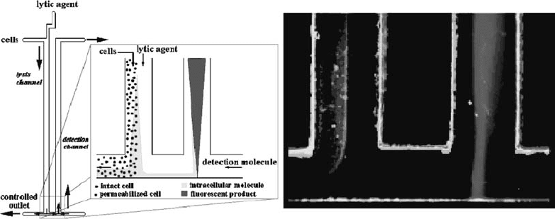
Different variants of the standard enzyme-linked immunosorbent
assay (ELISA) have been demonstrated on chip. A fast technique
based on the diffusion immunoassay (DIA) using flurogenic
enzymes to optically detect specific proteins was reported by Schil-
ling et al. (124). The chip integrates cell lysis and enzyme detec-
tion and is shown in Fig. 2.8.
A number of immunoassay systems have been demonstrated.
On-chip examples include the detection of HIV-1 from infected
and non-infected patients (125), the detection of cytokine tumour
necrosis factor with picomolar sensitivity (126), the integration of
standard immunostrip into microflow channels for the detection of
cardiac troponin I (marker for acute myocardial infarction) (127)
and the use of microfabricated filters for bead-based detection of
viruses (128). ELISA techniques combined with electrochemical
detection have also been demonstrated by Rossier et al. (129).
Fig. 2.8. Schematic view and fluorescence image of a diffusion immunoassay chip (DIA) for the detection of
b-galactosidase enzyme. The lytic agent and the cell suspension are introduced into the same flow channel. The lytic
agent diffuses into the cell suspension, lysing the cells. Intracellular components diffuse from the cell stream and a portion
flow into the detection channel, where their presence is detected by the production of a fluorescent species (resorfurine)
from a fluorogenic substrate. (Reproduced with permission from Schilling et al. (124), ª 2002 American Chemical
Society.)
74 Holmes and Gawad