Hibbeler R.C. Structural Analysis
Подождите немного. Документ загружается.

430 CHAPTER 10 ANALYSIS OF S TATICALLY INDETERMINATE STRUCTURES BY THE F ORCE METHOD
10
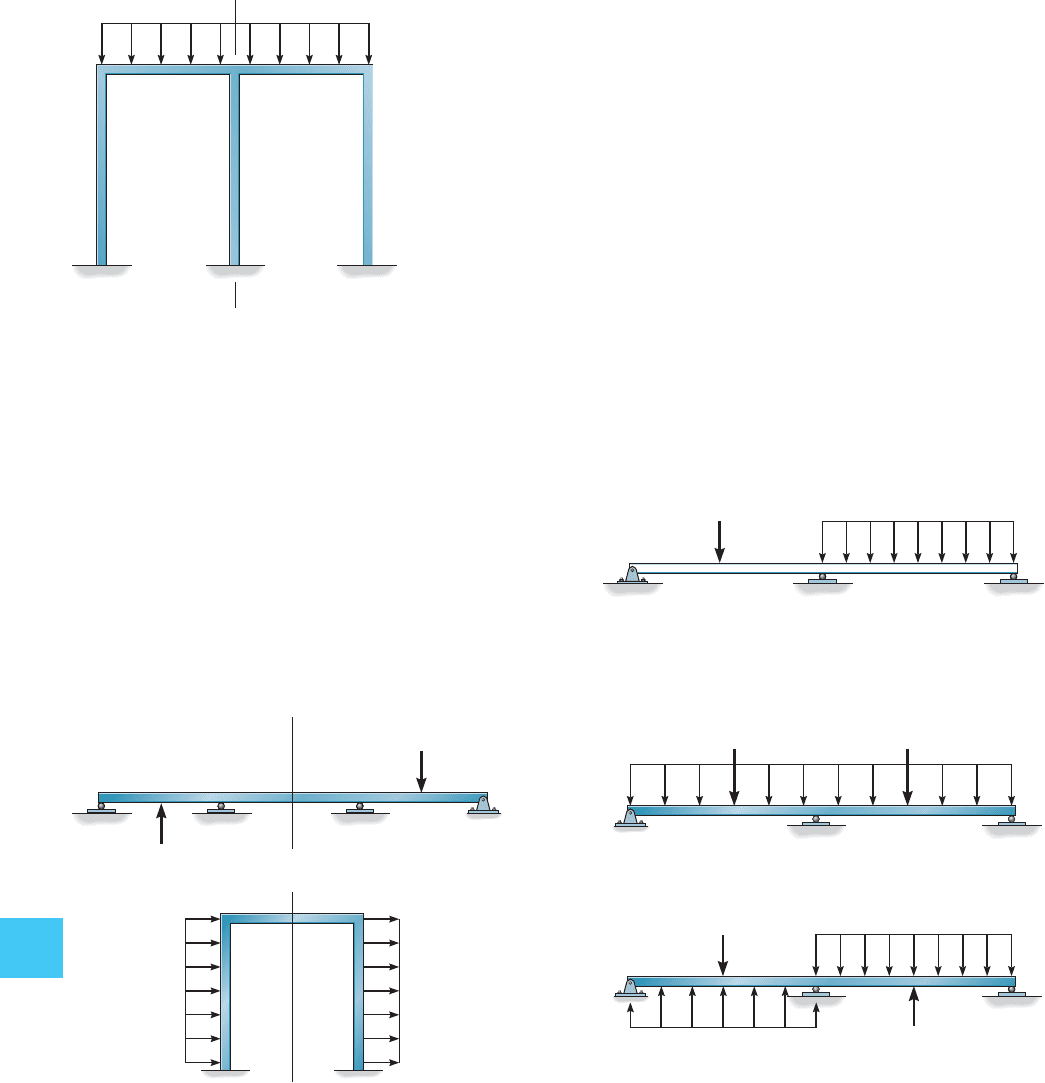
Sometimes a symmetric structure supports an antisymmetric loading,
that is, the loading on its reflected side has the opposite direction, such
as shown by the two examples in Fig. 10–18. Provided the structure is
symmetric and its loading is either symmetric or antisymmetric, then a
structural analysis will only have to be performed on half the members
of the structure since the same (symmetric) or opposite (antisymmetric)
results will be produced on the other half. If a structure is symmetric
and its applied loading is unsymmetrical, then it is possible to transform
this loading into symmetric and antisymmetric components. To do this,
the loading is first divided in half, then it is reflected to the other side of
the structure and both symmetric and antisymmetric components are
produced. For example, the loading on the beam in Fig. 10–19a is divided
by two and reflected about the beam’s axis of symmetry. From this, the
symmetric and antisymmetric components of the load are produced as
shown in Fig. 10–19b. When added together these components produce
the original loading.A separate structural analysis can now be performed
using the symmetric and antisymmetric loading components and the
results superimposed to obtain the actual behavior of the structure.
Antisymmetric loading
P
P
ww
8 kN
2 kN/m
ⴝ
(b)
4 kN
4 kN
1 kN/ m
ⴙ
symmetric loading
4 kN
4 kN
1 kN/ m
1 kN/m
antisymmetric loading
Fig. 10–18
Fig. 10–19
Fig. 10–17
axis of symmetry
(
c
)
A
w
(a)
10.9 SYMMETRIC STRUCTURES 431
10
2 in
2
2 in
2
2 in
2
2 in
2
2 in
2
3 in
2
3 in
2
3 in
2
A
3 ft
4 ft
5 k
B
C
D
E
4 ft
4 k
A
B
C
4 ft
8 k
6 k
3 ft
1 in.
2
1 in.
2
1 in.
2
1 in.
2
2 in.
2
2 in.
2
D
10 kN
D
C
B
E
A
3 m
3 m
4 m
A
C
D
B
3 ft
800 lb
3 ft
4 ft
Prob. 10–25
Prob. 10–26
Prob. 10–27
Prob. 10–28
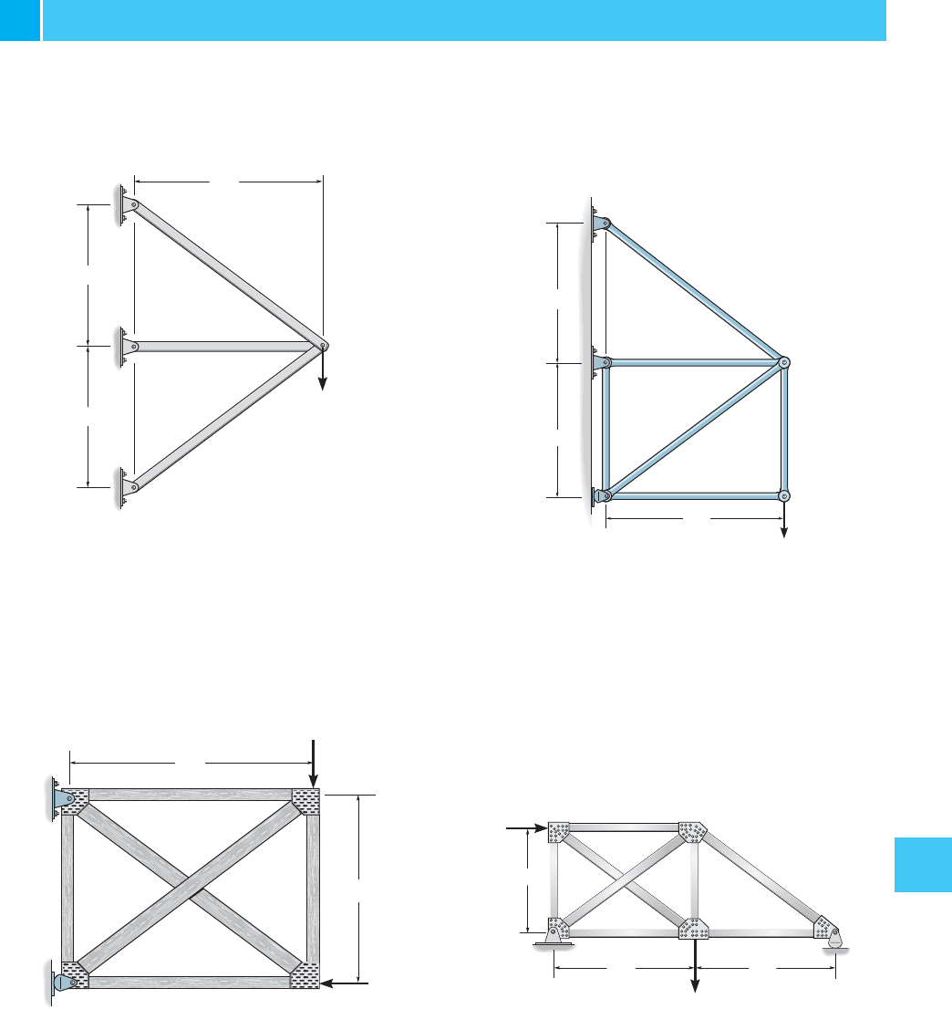
*10–28. Determine the force in member AD of the truss.
The cross-sectional area of each member is shown in the fig-
ure. Assume the members are pin connected at their ends.
Take .E = 29(10
3
) ksi
10–26. Determine the force in each member of the truss.
The cross-sectional area of each member is indicated in the
figure. . Assume the members are pin
connected at their ends.
E = 29(10
3
) ksi
10–27. Determine the force in member AC of the truss.
AE is constant.
10–25. Determine the force in each member of the truss.
AE is constant.
PROBLEMS
432 CHAPTER 10 ANALYSIS OF S TATICALLY INDETERMINATE STRUCTURES BY THE F ORCE METHOD
10
CDE
A
B
10 kN
20 kN
15 kN
2 m
2 m
2 m
B
A
C
4 m
3 m
9 kN
4 m4 m
D
10 ft
10 k
10ft 10 ft 10 ft
15 k 5 k
H
BC
D
E
A
GF
10 ft
2 k2 k
D
A
B
C
3 ft
3 ft
Prob. 10–29
Prob. 10–30
Prob. 10–31
Prob. 10–32
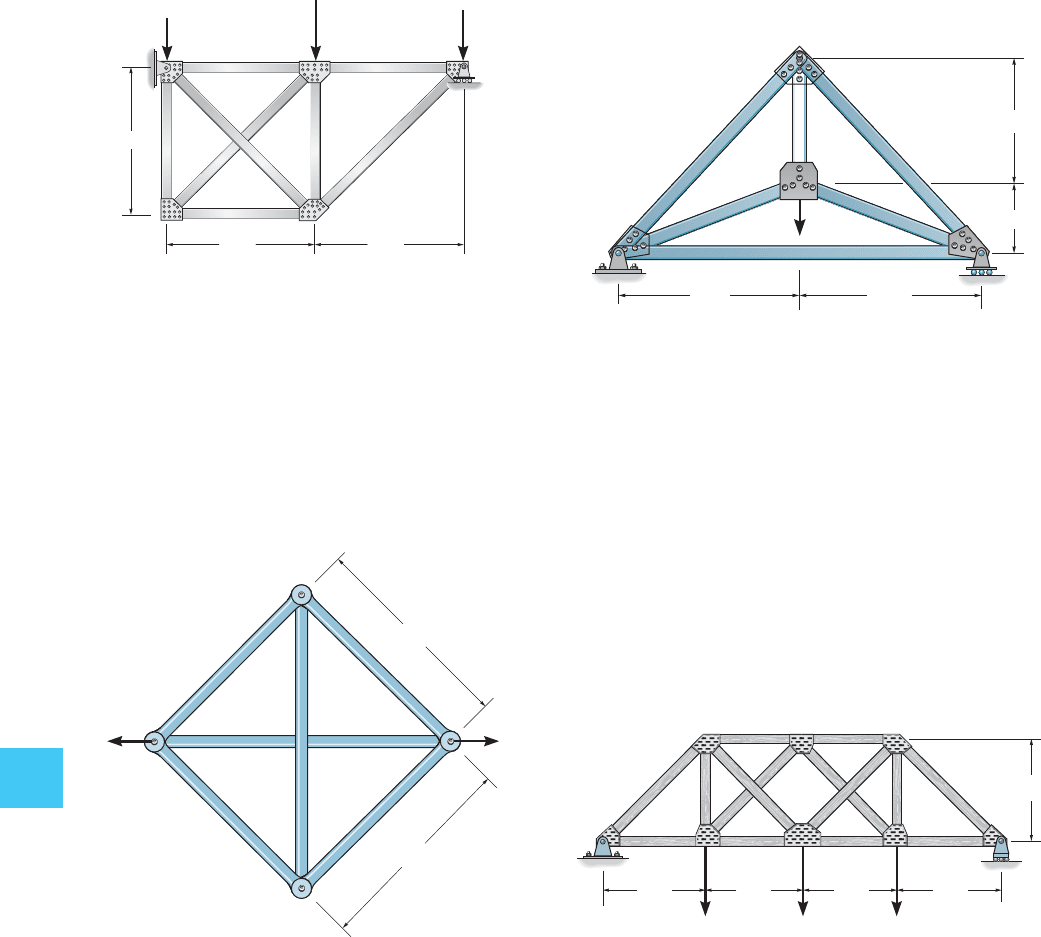
10–29. Determine the force in each member of the truss.
Assume the members are pin connected at their ends. AE is
constant.
10–31. Determine the force in member CD of the truss.
AE is constant.
10–30. Determine the force in each member of the pin-
connected truss. AE is constant.
*10–32. Determine the force in member GB of the truss.
AE is constant.
10.9 SYMMETRIC STRUCTURES 433
10
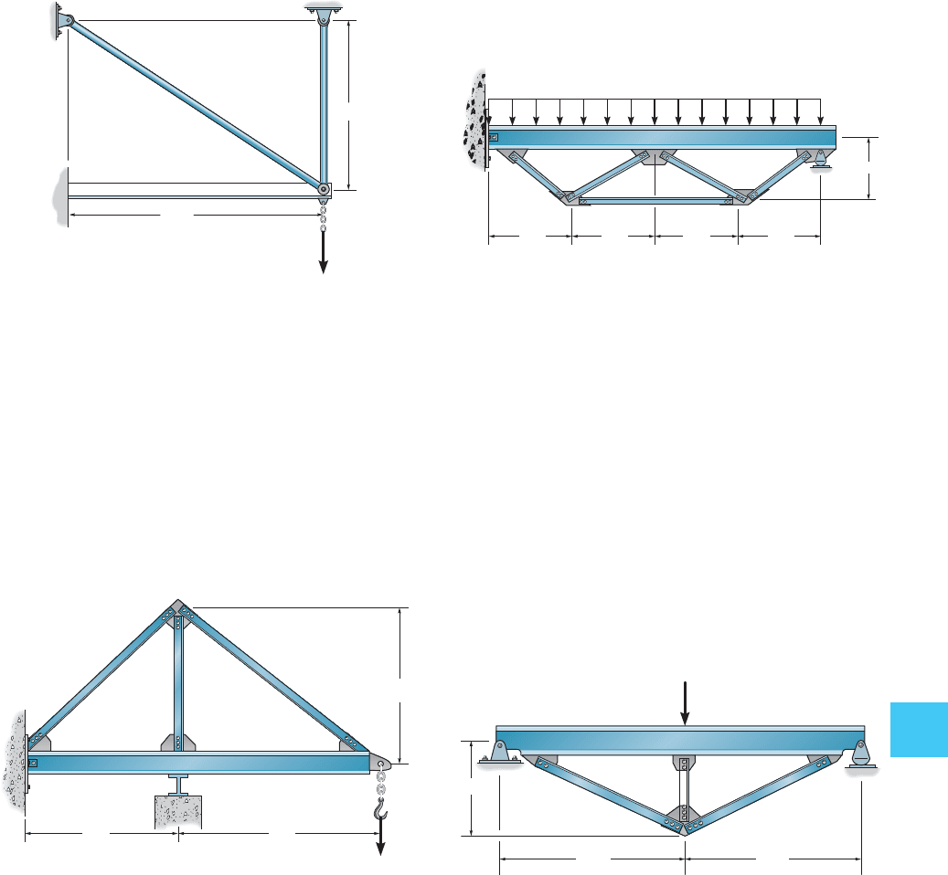
10–33. The cantilevered beam AB is additionally supported
using two tie rods. Determine the force in each of these
rods. Neglect axial compression and shear in the beam.
For the beam, , and for each tie rod,
. Take .E = 200 GPaA = 100 mm
2
I
b
= 200(10
6
) mm
4
10–35. The trussed beam supports the uniform distributed
loading. If all the truss members have a cross-sectional
area of 1.25 in
2
, determine the force in member BC. Neglect
both the depth and axial compression in the beam. Take
for all members. Also, for the beam
. Assume A is a pin and D is a rocker.I
AD
= 750
in
4
E = 29(10
3
) ksi
10–34. Determine the force in member AB, BC and BD
which is used in conjunction with the beam to carry the
30-k load. The beam has a moment of inertia of ,
the members AB and BC each have a cross-sectional area
of 2 in
2
, and BD has a cross-sectional area of 4 in
2
. Take
ksi. Neglect the thickness of the beam and its
axial compression, and assume all members are pin
connected. Also assume the support at A is a pin and E is
a roller.
E = 29110
3
2
I = 600
in
4
*10–36. The trussed beam supports a concentrated force
of 80 k at its center. Determine the force in each of the three
struts and draw the bending-moment diagram for the beam.
The struts each have a cross-sectional area of 2 in
2
. Assume
they are pin connected at their end points. Neglect both the
depth of the beam and the effect of axial compression in the
beam. Take ksi for both the beam and struts.
Also, for the beam .I = 400
in
4
E = 29110
3
2
4 m
80 kN
3 m
A
B
C
D
A
B
D
C
E
4 ft
4 ft4 ft 4 ft
3 ft
5 k/ ft
AB
C
D
80 k
12 ft
5 ft
12 ft
E
D
3 ft
CA
B
3 ft
4 ft
30 k
Prob. 10–33
Prob. 10–34
Prob. 10–35
Prob. 10–36
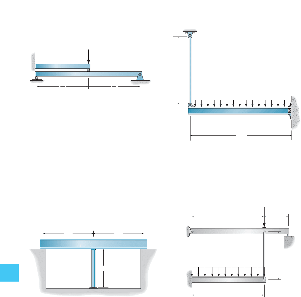
434 CHAPTER 10 ANALYSIS OF S TATICALLY INDETERMINATE STRUCTURES BY THE F ORCE METHOD
10
10–37. Determine the reactions at support C. EI is
constant for both beams.
*10–40. The structural assembly supports the loading
shown. Draw the moment diagrams for each of the beams.
Take for the beams and
for the tie rod. All members are made of steel for which
.E = 200 GPa
A = 200 mm
2
I = 100110
6
2
mm
4
10–39. The contilevered beam is supported at one end by
a -diameter suspender rod AC and fixed at the other
end B. Determine the force in the rod due to a uniform
loading of for both the beam and
rod.
4 k>ft. E = 29(10
3
) ksi
1
2
-in.
10–38. The beam AB has a moment of inertia
and rests on the smooth supports at its ends. A 0.75-in-
diameter rod CD is welded to the center of the beam and to
the fixed support at D. If the temperature of the rod is
decreased by 150°F, determine the force developed in the
rod. The beam and rod are both made of steel for which
and .a = 6.5(10
-6
)>F°E = 200 GPa
I = 475
in
4
AC
D
P
B
L
2
L
2
B
C
A
I
BC
350 in.
4
4 k/ft
20 ft
15 ft
50 in.
5 ft 5 ft
AB
C
D
6 m
8 kN/m
6 m
2 m
4 m
15 kN
A
B
C
D
E
Prob. 10–37
Prob. 10–40
Prob. 10–38
Prob. 10–39
10.10 INFLUENCE LINES FOR STATICALLY INDETERMINATE BEAMS 435
10
10.10 Influence Lines for Statically
Indeterminate Beams
In Sec. 6–3 we discussed the use of the Müller-Breslau principle for drawing
the influence line for the reaction, shear, and moment at a point in a
statically determinate beam. In this section we will extend this method
and apply it to statically indeterminate beams.
Recall that, for a beam, the Müller-Breslau principle states that the
influence line for a function (reaction, shear, or moment) is to the same
scale as the deflected shape of the beam when the beam is acted upon by
the function. To draw the deflected shape properly, the capacity of the
beam to resist the applied function must be removed so the beam can
deflect when the function is applied. For statically determinate beams, the
deflected shapes (or the influence lines) will be a series of straight line
segments. For statically indeterminate beams, curves will result. Construc-
tion of each of the three types of influence lines (reaction, shear, and
moment) will now be discussed for a statically indeterminate beam. In
each case we will illustrate the validity of the Müller-Breslau principle
using Maxwell’s theorem of reciprocal displacements.
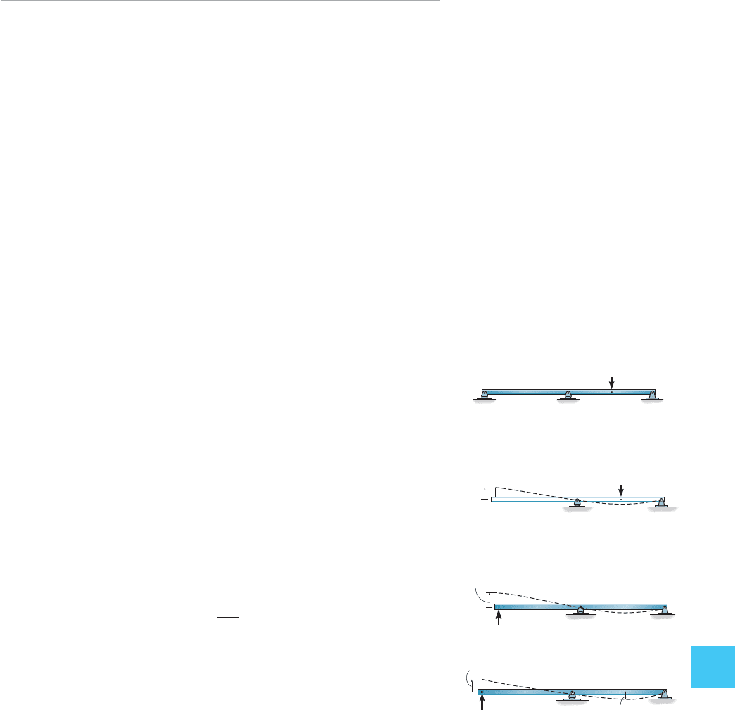
Reaction at
A
. To determine the influence line for the reaction at A
in Fig. 10–20a, a unit load is placed on the beam at successive points, and
at each point the reaction at A must be determined. A plot of these
results yields the influence line. For example, when the load is at point D,
Fig. 10–20a, the reaction at A, which represents the ordinate of the
influence line at D, can be determined by the force method. To do this,
the principle of superposition is applied, as shown in Figs. 10–20a
through 10–20c. The compatibility equation for point A is thus
or however, by Maxwell’s theorem
of reciprocal displacements Fig. 10–20d, so that we can
also compute (or the ordinate of the influence line at D) using the
equation
By comparison, the Müller-Breslau principle requires removal of the
support at A and application of a vertical unit load. The resulting deflec-
tion curve, Fig. 10–20d, is to some scale the shape of the influence line for
From the equation above, however, it is seen that the scale factor is
1>f
AA
.
A
y
.
A
y
= a
1
f
AA
bf
DA
A
y
f
AD
=-f
DA
,
A
y
=-f
AD
>f
AA
;0 = f
AD
+ A
y
f
AA
f
AA
A
C
B
(d)
1
D
f
DA
A
y
f
AA
A
C
B
(c)
redundant A
y
applied
A
y
f
AD
A
C
B
(b)
1
D
primary structure
ⴝ
ⴙ
Fig. 10–20
AC
B
(a)
1
D
actual beam
436 CHAPTER 10 ANALYSIS OF S TATICALLY INDETERMINATE STRUCTURES BY THE F ORCE METHOD
10
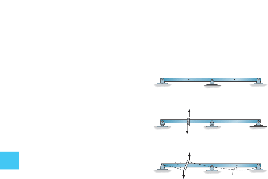
Shear at
E
. If the influence line for the shear at point E of the
beam in Fig. 10–21a is to be determined, then by the Müller-Breslau
principle the beam is imagined cut open at this point and a sliding
device is inserted at E, Fig. 10–21b. This device will transmit a moment
and normal force but no shear. When the beam deflects due to positive
unit shear loads acting at E, the slope on each side of the guide remains
the same, and the deflection curve represents to some scale the
influence line for the shear at E, Fig. 10–21c. Had the basic method for
establishing the influence line for the shear at E been applied, it would
then be necessary to apply a unit load at each point D and compute the
internal shear at E, Fig. 10–21a. This value, would represent the
ordinate of the influence line at D. Using the force method and
Maxwell’s theorem of reciprocal displacements, as in the previous case,
it can be shown that
This again establishes the validity of the Müller-Breslau principle,
namely, a positive unit shear load applied to the beam at E,
Fig. 10–21c, will cause the beam to deflect into the shape of the influ-
ence line for the shear at E. Here the scale factor is 11>f
EE
2.
V
E
= a
1
f
EE
bf
DE
V
E
,
(a)
DE
AC
(b)
E
1
1
(c)
E
1
1
f
EE
D
f
DE
Fig. 10–21
10.10 INFLUENCE LINES FOR STATICALLY INDETERMINATE BEAMS 437
10
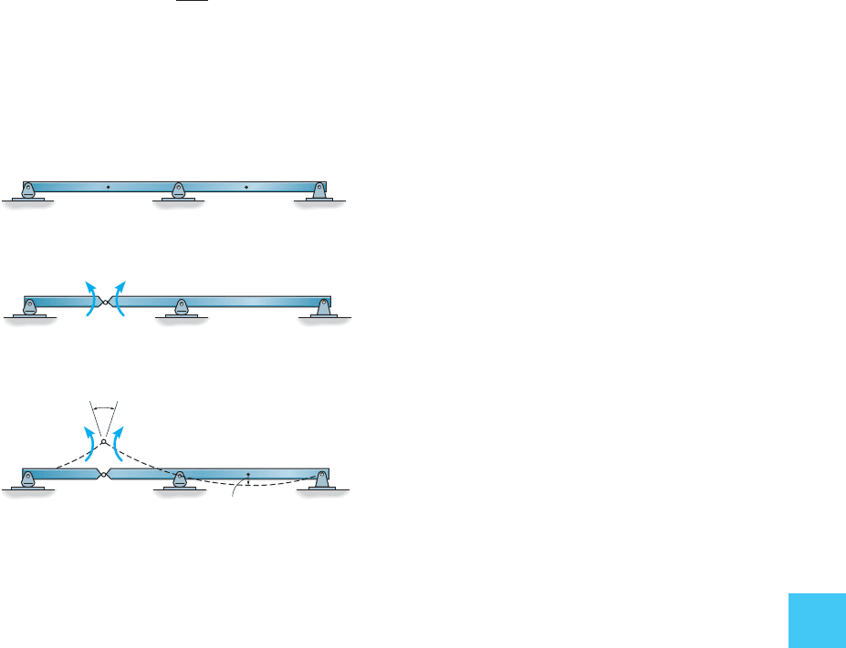
Moment at
E
. The influence line for the moment at E in
Fig. 10–22a can be determined by placing a pin or hinge at E, since this
connection transmits normal and shear forces but cannot resist a
moment, Fig. 10–22b. Applying a positive unit couple moment, the beam
then deflects to the dashed position in Fig. 10–22c, which yields to some
scale the influence line, again a consequence of the Müller-Breslau
principle. Using the force method and Maxwell’s reciprocal theorem, we
can show that
The scale factor here is 11>a
EE
2.
M
E
= a
1
a
EE
bf
DE
Fig. 10–22
(
a
)
DE
AC
(b)
E
11
(
c
)
E
11
D
f
DE
a
EE
438 CHAPTER 10 ANALYSIS OF S TATICALLY INDETERMINATE STRUCTURES BY THE F ORCE METHOD
10
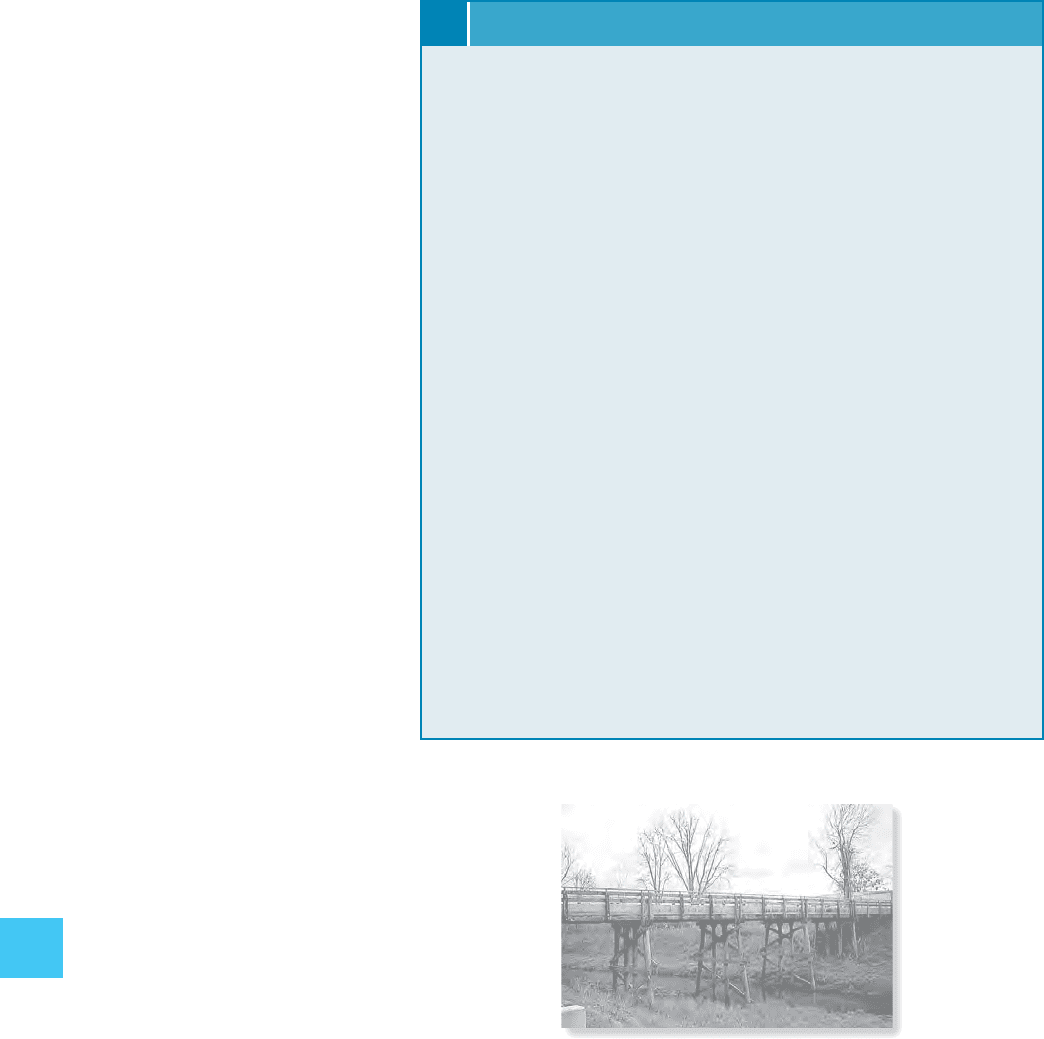
Influence lines for the continuous girder of
this trestle were constructed in order to prop-
erly design the girder.
Procedure for Analysis
The following procedure provides a method for establishing the
influence line for the reaction, shear, or moment at a point on a
beam using the Müller-Breslau technique.
Qualitative Influence Line
At the point on the beam for which the influence line is to be
determined, place a connection that will remove the capacity of the
beam to support the function of the influence line. If the function is
a vertical reaction, use a vertical roller guide; if the function is shear,
use a sliding device; or if the function is moment, use a pin or hinge.
Place a unit load at the connection acting on the beam in the “positive
direction” of the function. Draw the deflection curve for the beam.
This curve represents to some scale the shape of the influence line
for the beam.
Quantitative Influence Line
If numerical values of the influence line are to be determined,
compute the displacement of successive points along the beam when
the beam is subjected to the unit load placed at the connection
mentioned above. Divide each value of displacement by the
displacement determined at the point where the unit load acts. By
applying this scalar factor, the resulting values are the ordinates of
the influence line.
10.11 QUALITATIVE INFLUENCE LINES FOR FRAMES 439
10
Fig. 10–23
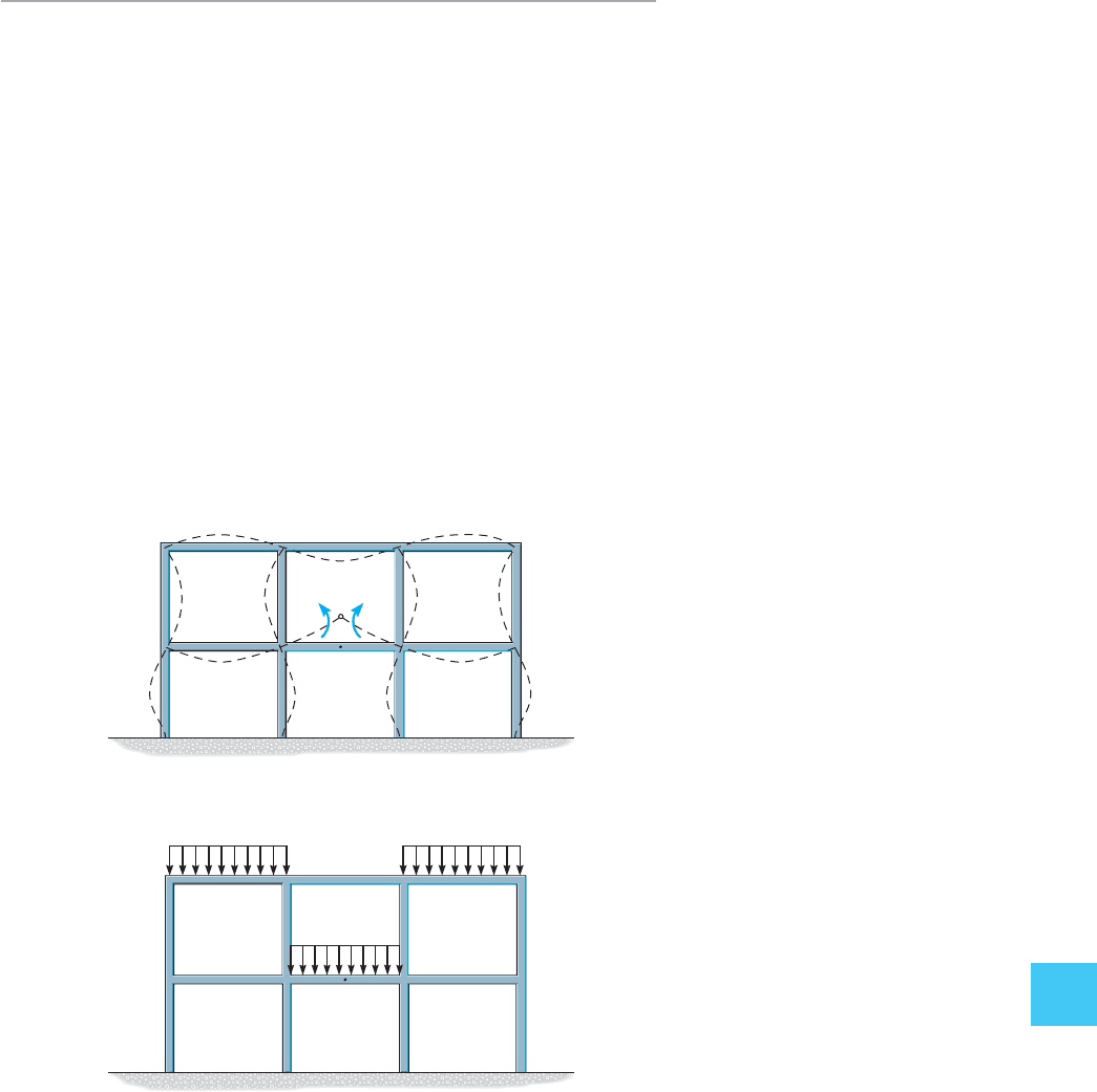
10.11 Qualitative Influence Lines
for Frames
The Müller-Breslau principle provides a quick method and is of great
value for establishing the general shape of the influence line for building
frames. Once the influence-line shape is known, one can immediately
specify the location of the live loads so as to create the greatest influence
of the function (reaction, shear, or moment) in the frame. For example,
the shape of the influence line for the positive moment at the center I of
girder FG of the frame in Fig. 10–23a is shown by the dashed lines. Thus,
uniform loads would be placed only on girders AB, CD, and FG in order
to create the largest positive moment at I. With the frame loaded in this
manner, Fig. 10–23b, an indeterminate analysis of the frame could then
be performed to determine the critical moment at I.
A
E
B
F
C
G
D
H
I
(a)
A
E
B
F
C
G
D
H
I
(b)
