Heywood J.B. Internal Combustion Engines Fundamentals
Подождите немного. Документ загружается.

850
INTERNAL COMBUSTION
ENGINE
FUNDAMENTALS
More rapid initial flame growth results in less variation in flame center motion
during the critical flame-development phase. The resulting geometric variations
in the flame frontlchamber wall interaction are therefore reduced; this decreases
the variations in burn rate that result from these geometric variations. Also, the
faster burning process ends earlier in the expansion stroke. Thus the problem of
occasional slow burning cycles, partial burning cycles, and eventually misfire,
which occurs with dilute mixtures under normal burning conditions due to quen-
ching of the combustion process
as
gas temperatures fall during expansion, is
largely avoided (see Sec. 9.4.3).
15.43
Factors That Control Performance
VOLUMETRIC
EFFICIENCY.
Combustion chamber shape affects volumetric efi-
ciency through its constraints on maximum valve size and through the degree of
swirl
(if
any) that the chamber and port designs produce to achieve the desired
combustion characteristics. To obtain maximum performance and to reduce
pumping losses, the size of the valve heads should be as large as practical; the
valve sizes that can be accommodated depend on cylinder head layout. Table 6.1
lists the typical maximum valve sizes that can be accommodated into several
common chamber shapes (see Fig. 15-15). The approximate mean piston speed at
maximum power is a measure of the maximum air flow that each engine design
can pump. Note that of the two-valve configurations, the designs with inclined
valve stems permit substantially greater maximum air flow. The four-valve pent-
roof design, which also has inclined valve stems, is the best of those listed since it
accommodates the largest valve and port areas (there are other four-valve head
designs which are comparable).
Swirl can be generated during the intake process through suitable port,
valve, and head design. It requires either that the flow through the intake valve
be directed tangentially into the cylinder so that gas flows through one side of the
valve opening preferentially
(e.g., through the use of masks to restrict flow at the
mask location or through the use of a tangentially directed port or a flow deflec-
tor in the port just upstream of the valve), or requires the use of a helical intake
port that imparts an angular velocity to the flow before it enters the cylinder. In
either case the inlet flow enters the cylinder with higher velocity than it would
have in the absence of swirl; hence the pressure drop across the valve is
increased, and maximum air flow through the cyiinder is reduced. Well-designed
helical swirl-generating ports (see
Sec. 8.3.2) appear to be the best way to create
swirl. However, geometric and production constraints often prevent the incorpo-
ration of such ports into the cylinder head design, and other swirl-generating
methods must be used. The engine maximum-power penalty associated with gen-
erating significant swirl is of order 5 to 10 per cent.
Since swirl is only required at part-throttle operation when enhancement of
the burn rate is most critical and is not usually required at full throttle when the
flow restriction penalty is most significant, induction systems with a separate
passage for the part-throttle air flow, where only this separate passage generates
swirl, are an attractive option. However, the gains in volumetric efficiency are
offset by a higher cost due to the additional complexity in port and manifold of
the double passage and the individual throttle valves required in each port for
flow control.
Swirl can be
intensijed
during compression with bowl-in-piston combustion
chambers by decreasing the moment of inertia of the in-cylinder charge as the
piston moves toward top-center, and thereby increasing its angular velocity (see
Sec. 8.3.3). An advantage here is that the swirl level generated during induction is
less than would be required without the compression-produced radially inward
motion of the charge. This approach can be used with combustion chamber
designs that are axisymrnetric and compact. Swirl can also
be
generated
by squish
motion toward the end of compression with a suitable design of chamber. The
advantage of this approach is that there is no induction-stroke swirl-generating
volumetric efficiency penalty. However, the cylinder head geometries proposed to
date for either intensifying or generating swirl have vertical valve stems, and
hence have smaller valve sizes which in themselves restrict air flow. Also, the
cylinder head geometry required to generate swirl during compression has a
larger surface area than more open chamber designs and, therefore, has signifi-
cantly higher heat losses.
The impact of conventional radially inward squish motion (see
Sec. 8.4) on
in-cylinder turbulence, and hence combustion, is unclear. Chambers with signifi-
cant squish are also more compact; for this reason alone they would
be
faster
burning.
HEAT
TRANSFER.
The convective engine heat transfer to the combustion
chamber walls is described by equations of the form of (12.2): e.g., Eq. (12.21).
The heat-transfer coefficient is usually correlated by expressions of the form of
Eq.
(12.3), which relate the Nusselt, Reynolds, and Prandtl numbers (see Sec.
12.4). Thus combustion chamber surface area, and especially the surface area in
contact with the burned gases, is important. Gas velocity is also important; it
influences the heat-transfer rate through the Reynolds number. Various charac-
teristic velocities have been used in the Reynolds number to scale heat transfer:
mean piston speed, mean in-cylinder gas velocity, turbulence intensity, either
individually or in combination. Both of these variables, area and velocity, are
affected by combustion chamber design.
Studies of engine performance using thermodynamic-based simulations of
the engine's operating cycle (see Sec. 14.4) provide data that indicate the impor-
tance of changes in heat transfer. At part-throttle operating conditions, such
simulation calculations show that a 10 percent change in combustion chamber
heat losses results in a change of between 2 and
5
percent in brake specific fuel
consumption; an average fuel consumption change of about one-third the magni-
tude of the heat-transfer change (and of opposite sign) is an appropriate rule of
thumb.25*
"
At wide-open throttle, the effect on mean effective pressure is compa-
rable: a 10 percent change in heat transfer results in about a 3 percent change in
bmep.
This impact of heat transfer on engine efficiency and performance under-
lines the importance of combustion chamber details that affect heat transfer. For
the chamber shapes shown in Fig. 15-16, the total heat losses as a fraction of the
fuel's energy, at fixed engine speed and intake conditions, were also calculated.
Both chamber shape and spark plug details affect heat losses since together these
govern the surface area of the hot burned gases in contact with the walls. The
open and hemispherical chambers had least heat transfer. Geometries such as the
bowl-in-piston, which obviously have a higher surface area, had about 10 percent
higher heat transfer. The effect of shifting the plug from a side to center location
depended on chamber shape. Open and bowl-in-piston chambers showed little
change; the hemispherical chamber showed a
4
percent reduction. Given
a
general chamber shape choice, the details of the actual design are important also;
it is easy to add substantial surface area with piston cutouts, plug bosses, and
cylinder head masking or squish regions which will deteriorate chamber per-
formance to a measurable degree.
Higher in-cylinder velocities affect heat-transfer rates through the Reynolds
number term in the heat-transfer coefficient correlation. Swirl- and
squish-
generated flows increase in-cylinder gas velocities and will, therefore, increase
heat-transfer rates.
15.4.4
Chamber
Octane Requirement
Knock limits an engine's compression ratio, and hence its performance and effi-
ciency. The more fundamental aspects of knock were reviewed in Sec. 9.6. Knock
occurs when the end-gas autoignites prior to its being burned up by the normal
flame-propagation process. The tendency to knock depends on engine design and
operating variables which influence end-gas temperature, pressure, and time
spent at high values of these two properties before flame arrival.
The presence or absence of knock in an engine depends primarily on the
antiknock quality of the fuel, which is defined by the fuel's
octane number
(see Sec.
9.6.3). It determines whether or not a fuel will knock in a given engine under
given operating conditions: the higher the octane number, the higher the resist-
ance to knock. The
octane number requirement
of an engine is defined as the
minimum fuel octane number that will resist knock throughout its speed and
load range. The following factors affect an engine's octane requirement: (1) com-
position of the fuel; (2) chamber geometry and size; (3) charge motion;
(4)
spark-
advance curve; (5) inlet air, intake manifold, and water jacket temperatures; (6)
carburetor or fuel-injector air-fuel ratio calibration;
(7)
the ambient conditions-
pressure, temperature, and relative humidityduring the requirement determi-
nation.
The following illustrates the interaction between fuel factors and engine
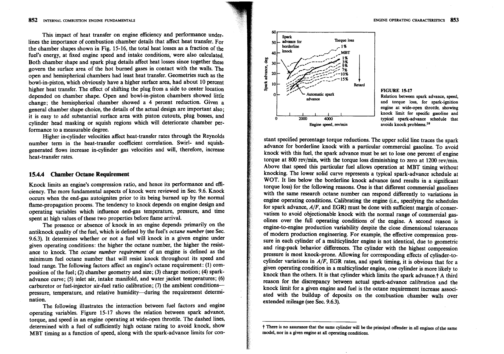
operating variables. Figure 15-17 shows the relation between spark advance,
torque, and speed in an engine operating at wide-open throttle. The dashed lines,
determined with a fuel of sufficiently
high
octane rating to avoid knock, show
MBT timing as
a
function of speed, along with the spark-advance limits for con-
ENGINE OPERATING CHARACTERISTICS
853
Torque loss
-
1%
knock
,-
Retard
V)
Automatic
spark
I
advance
FIGURE
15-17
Relation between spark advance, speed,
and torque loss, for spark-ignition
I
-
-
I
engine a; wide-om throttle, showing
1
I
I
I
I
I
I
knock limit for
specific
gasoline and
0
2000
4000
typical spark-advance schedule that
Engine
speed,
revlmin avoids knock problems.28
stant specified percentage torque reductions. The upper solid line traces the spark
advance for borderline knock with a particular commercial gasoline. To avoid
knock with this fuel, the spark advance must be set to lose one percent of engine
torque at
800
rev/min, with the torque loss diminishing to zero at 1200 revlmin.
Above that speed this particular fuel allows operation at MBT timing without
knocking. The lower solid curve represents a typical spark-advance schedule at
WOT. It lies below the borderline knock advance (and results in a significant
torque loss) for the following reasons. One is that different commercial gasolines
with the same research octane number can respond differently to variations in
engine operating conditions. Calibrating the engine
(i.e., specifying the schedules
for spark advance, A/F, and EGR) must
be
done with sufficient margin of conser-
vatism to avoid objectionable knock with the normal range of commercial gas-
oline~ over the full operating conditions of the engine. A second reason is
engine-to-engine production variability despite the close dimensional tolerances
of modem production engineering. For example, the effective compression pres-
sure in each cylinder of a multicylinder engine is not identical, due to geometric
and ring-pack behavior differences. The cylinder with the highest compression
pressure is most knock-prone. Allowing for corresponding effects of
cylinder-to-
cylinder variations in AIF,
EGR
rates, and spark timing, it is obvious that for a
given operating condition in a multicylinder engine, one cylinder is more likely to
knock than the others. It is that cylinder which limits the spark advance.? A third
reason for the discrepancy between actual spark-advance calibration and the
knock limit for a given engine and fuel is the octane requirement increase associ-
ated with the buildup of deposits on the combustion chamber walls over
extended mileage (see
Sec. 9.6.3).
t
There
is no assurance that the
same
cylinder
will
be
the principal offender in
all
engines of the same
model, nor
in
a given engine at
all
operating conditions.
854
INTERNAL COMBUSTION ENGINE FUNDAMENTALS
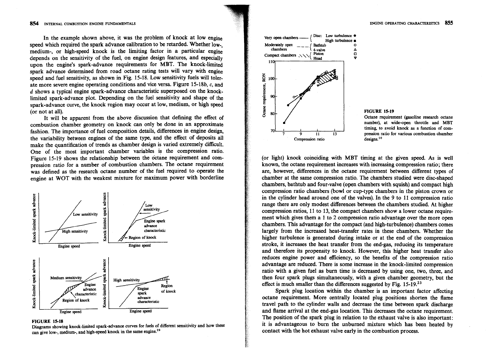
In the example shown above, it was the problem of knock at low engine
speed which required the spark advance calibration to be retarded. Whether low-,
medium-, or high-speed knock is the limiting factor in a particular engine
depends on the sensitivity of the fuel, on engine design features, and especially
upon the engine's spark-advance requirements for
MBT.
The knock-limited
spark advance determined from road octane rating tests will vary with engine
speed and fuel sensitivity, as shown in Fig. 15-18. Low sensitivity fuels will toler-
ate more severe engine operating conditions and vice versa. Figure 15-18b,
c,
and
d
shows a typical engine spark-advance characteristic superposed on the knock-
limited spark-advance plot. Depending on the fuel sensitivity and shape of the
spark-advance curve, the knock region may occur at low, medium, or high speed
(or not at all).
It will be apparent from the above discussion that defining the effect of
combustion chamber geometry on knock can only be done in an approximate
fashion. The importance of fuel composition details, differences in engine design,
the variability between engines of the same type, and the effect of deposits all
make the quantification of trends as chamber design is varied extremely difficult.
One of the most important chamber variables is the compression ratio.
Figure 15-19 shows the relationship between the octane requirement and com-
pression ratio for a number of combustion chambers. The octane requirement
was defined as the research octane number of the fuel required to operate the
engine at WOT with the weakest mixture for maximum power with borderline
Low
sensitivity
/
High sensitivity
F
senslttvity
characteristic
A-
Region of
knock
Engine
speed
Engine
speed
'3
.-
d
advance
characteriskic
Engine
speed
Engine speed
FIGURE
15-18
Diagrams showing knock-limited spark-advance curves for fuels of different sensitivity and how these
can
give low-, medium-, and high-speed knock in the same engine.2g
chambers
1
4-valve
A
Compact
chambers
.\\\{
0
v
I
1
9
It 13
Compression ratio
FIGURE
15-19
Octane requirement (gasoline research octane
number), at wide-open throttle and
MBT
timing,
to avoid knock
as
a function of
com-
pression ratio for various combustion chamber
designs.1•‹
(or light) knock coinciding with MBT timing at the given speed. As is well
known, the octane requirement increases with increasing compression ratio; there
are, however, differences in the octane requirement between different types of
chamber at the same compression ratio. The chambers studied were disc-shaped
chambers, bathtub and four-valve (open chambers with squish) and compact high
compression ratio chambers (bowl or cup-type chambers in the piston crown or
in the cylinder head around one of the valves). In the 9 to 11 compression ratio
range there are only modest differences between the chambers studied. At higher
compression ratios, 11 to 13, the compact chambers show a lower octane require-
ment which gives them a 1 to
2
compression ratio advantage over the more open
chambers. This advantage for the compact (and high-turbulence) chambers comes
largely from the increased heat-transfer rates in these chambers. Whether the
higher turbulence is generated during intake or at the end of the compression
stroke, it increases the heat transfer from the end-gas, reducing its temperature
and therefore its propensity to knock. However, this higher heat transfer also
reduces engine power and
efficiency, so the benefits of the compression ratio
advantage are reduced. There is some increase in the knock-limited compression
ratio with a given fuel as bum time is decreased by using one, two, three, and
then four spark plugs simultaneously, with a given chamber geometry, but the
effect is much smaller than the differences suggested by Fig.
15-19.23
Spark plug location within the chamber is
an
important factor affecting
octane requirement. More centrally located plug positions shorten the flame
travel path to the cylinder walls and decrease the time between spark discharge
and flame
amval at the end-gas location. This decreases the octane requirement.
The position of the spark plug in relation to the exhaust valve is also important:
it is advantageous to burn the unburned mixture which has been heated by
contact with the hot exhaust valve early in the combustion process.
856
INTERNAL
COMBUSTION
ENGINE
FUNDAMENTALS
TABLE
15.2
Engine
conditions
affecting
octane
number requirement
Octane
number
rep.irement
octane
number
requirement
tends to
go
yp
when:
tends
to
p
down
when:
1. Ignition timing is advanced.
1. Ignition timing is retarded.
2.
Air density
rises
due to
2.
Engine
is operated at
highcr
supercharging or a larger
altitudes or smaller throttle
throttle opening or higher
opening or lower barometric
barometric pressure. pressure.
3.
Humidity or moisture content
3.
Humidity of the air increases.
of the air decreases.
4.
Inlet air temperature
is
increased.
5.
Coolant temperature is
raised.
6.
Antifreeze (glycol) engine
coolant is used.
7.
Engine load is increased.
4.
Inlet
air
temperature is
decreased.
5.
Fuellair ratio
is
richer or
leaner than that producing
maximum knock.
6.
Exhaust gas recycle system
operates at part throttle.
7.
Engine load is reduced.
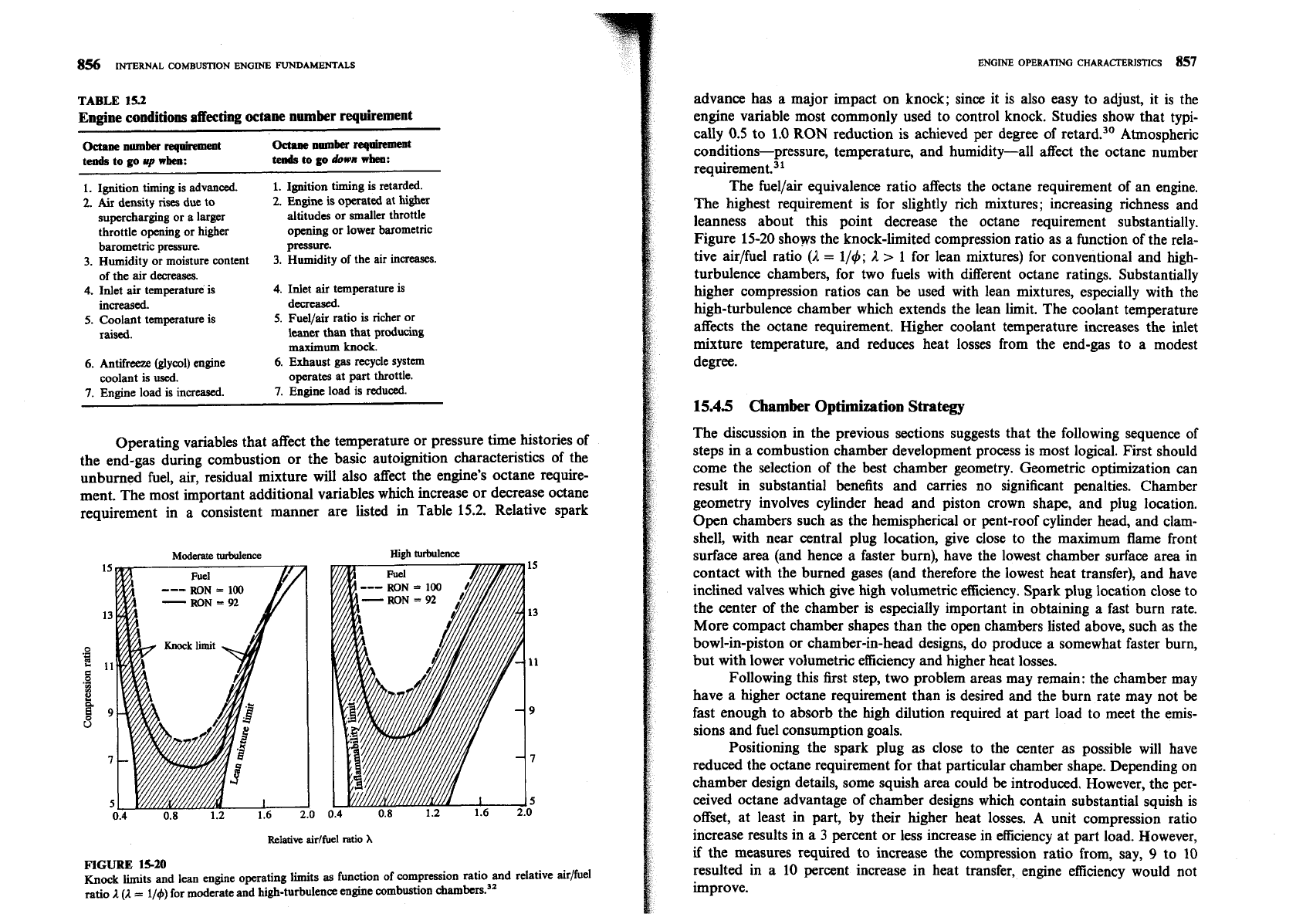
Operating variables that affect the temperature or pressure time histories of
the end-gas during combustion or the basic autoignition characteristics of the
unburned fuel,
air,
residual mixture will also affect the engine's octane require-
ment. The most important additional variables which increase or decrease octane
requirement in a consistent manner are listed in Table
15.2.
Relative spark
Moderate
turbulence
Hi&
turbulence
Relative.
aidfuel
ratio
X
FIGURE
15-20
Knock
lits and lean engine operating limits
as
function of compression ratio and relative air/fuel
ratio
I (I
=
114) for moderate and high-turbulence engine combustion
advance has a major impact on knock; since it is also easy to adjust, it is the
engine variable most commonly used to control knock. Studies show that typi-
cally
0.5
to
1.0
RON
reduction is achieved per degree of retard.30 Atmospheric
conditions-pressure, temperature, and humidity-all affect the octane number
req~irement.~~
The fuellair equivalence ratio affects the octane requirement of an engine.
The highest requirement is for slightly rich mixtures; increasing richness and
leanness about this point decrease the octane requirement substantially.
Figure
15-20
shops the knock-limited compression ratio as a function of the rela-
tive air/fuel ratio
(2
=
114;
2
>
1 for lean mixtures) for conventional and high-
turbulence chambers, for two fuels with different octane ratings. Substantially
higher compression ratios can
be
used with lean mixtures, especially with the
high-turbulence chamber which extends the lean limit. The coolant temperature
affects the octane requirement. Higher coolant temperature increases the inlet
mixture temperature, and reduces heat losses from the end-gas to a modest
degree.
15.45
Chamber
Optimization
Strategy
The discussion in the previous sections suggests that the following sequence of
steps in a combustion chamber development process is most logical. First should
come the selection of the best chamber geometry. Geometric optimization can
result in substantial benefits and carries no significant penalties. Chamber
geometry involves cylinder head and piston crown shape, and plug location.
Open chambers such as the hemispherical or pent-roof cylinder head, and clam-
shell, with near central plug location, give close to the maximum flame front
surface area (and hence a faster burn), have the lowest chamber surface area in
contact with the burned gases (and therefore the lowest heat transfer), and have
inclined valves which give high volumetric efficiency. Spark plug location close to
the center of the chamber
is
especially important in obtaining a fast burn rate.
More compact chamber shapes than the open chambers listed above, such as the
bowl-in-piston or chamber-in-head designs, do produce a somewhat faster burn,
but with lower volumetric efficiency and higher heat losses.
Following this first step, two problem areas may remain: the chamber may
have a higher octane requirement than is desired and the burn rate may not
be
fast enough to absorb the high dilution required at part load to meet the emis-
sions and fuel consumption goals.
Positioning the spark plug as close to the center as possible will have
reduced the octane requirement for that particular chamber shape. Depending on
chamber design details, some squish area could
be
introduced. However, the per-
ceived octane advantage of chamber designs which contain substantial squish is
offset, at least in part, by their higher heat losses. A unit compression ratio
increase results in a
3
percent or less increase in efficiency at part load. However,
if
the measures required to increase the compression ratio from, say,
9
to
10
resulted in a
10
percent increase in heat transfer, engine efficiency would not
improve.
The next step should be to reduce the cyclic variability in the combustion
process to the maximum extedt feasible, by improving the uniformity of the
intake fuel, air, and
EGR
mixture. Delivery of equal amounts of each of these
constituents to each cylinder, provision for good mixing between constituents in
the intake manifold and port, and accurate control of mixture composition
during engine transients are all especially important. Also important is achieving
closely similar flow patterns within each engine cylinder during intake so as to
obtain equal burn rates in all cylinders. Attention to these intake process and
mixture preparation details will always improve engine operation and carries no
performance penalties.
However, the bum rate may still not be fast enough, especially during the
critical early stages of flame development, and cyclic variability may still be too
high to meet the engine's performance goals. Then higher
turbxlence levels
during combustion must be achieved. This is usually best done by creating swirl
during the induction process. The appropriate method for introducing swirl will
depend on any geometric manufacturing constraints and cost issues. With no
geometric constraints, use of helical swirl-generating ports or a divided
intake-
port system with valves to control the flow at light load are likely to have the
lowest power penalties. It is especially important that only the minimum addi-
tional turbulence required to achieve the performance objectives be added at this
stage. Higher than necessary gas velocities within the cylinder result in excessive
heat losses and low volumetric efficiency.
In summary, to meet the objectives of a fast, repeatable, and robust com-
bustion process with high volumetric efficiency, low heat transfer, and acceptable
octane requirement, combustion chamber development should proceed through
the following steps.
1.
Optimize the chamber geometry within the design constraints for the
maximum flame front area, minimum burned gaslchamber wall contact area,
and largest valve size.
2.
Obtain additional reductions in the cyclic combustion variability by improv-
ing mixture distribution and uniformity and by creating flow patterns into
each cylinder that are essentially identical.
3.
Achieve any additional improvement in bum rate and cyclic variability
required to meet objectives by increasing turbulence to the minimum extent.
This is usually best done by creating swirl during the induction process.
155
VARIABLES THAT AFFECT CI
ENGINE PERFORMANCE, EFFICIENCY,
AND EMISSIONS
155.1
Load
and
Speed
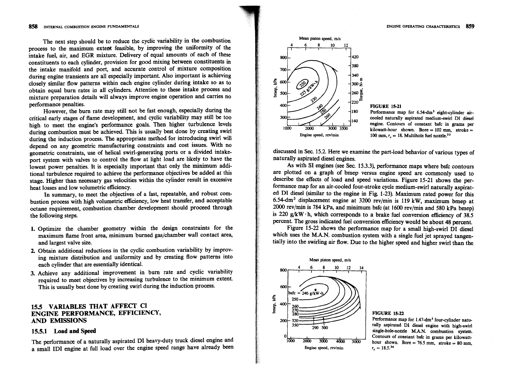
The performance of
a
naturally aspirated DI heavy-duty truck diesel engine and
a small ID1 engine at full load over the engine speed range have already been
Mean
piston
speed, mls
800
FIGURE
15-21
Performance map for 6.W3 eight-cylinder air-
cooled naturally aspirated medium-swirl
DI
diesel
engine. Contours of constant bsfc in grams per
Kilowatt-hour shown. Bore
=
102
mm,
stroke
=
Engine
speed, mlmin
100
mm,
r,
=
18.
Multihole fuel
discussed in Sec. 15.2. Here we examine the part-load behavior of various types of
naturally aspirated diesel engines.
As with
SI
engines (see Sec. 15.3.3), performance maps where bsfc contours
are plotted on a graph of bmep versus engine speed are commonly used to
describe the effects of load and speed variations. Figure 15-21 shows the per-
formance map for an air-cooled four-stroke cycle medium-swirl naturally aspirat-
ed DI diesel
(similar to the engine in Fig. 1-23). Maximum rated power for this
6.54-dm3 displacement engine at 3200 revlmin is 119 kW, maximum bmep at
2000 revlmin is
784
kPa, and minimum bsfc (at 1600 revlmin and 580 kPa bmep)
is 220 g/kW. h, which corresponds to a brake fuel conversion efficiency of 38.5
percent. The gross indicated fuel conversion efficiency would be about 48 percent.
Figure 15-22 shows the performance map for a small high-swirl DI diesel
which uses the M.A.N. combustion system with a single fuel jet sprayed tangen-
tially into the swirling
air
flow. Due to the higher speed and higher swirl than the
Mean
piston
speed,
mls
8001
1
4
6
8
10 12 14
1
I
I
I
I
0
1
I
I
loo0
2000
3000
4ooo
5000
Engine
speed,
revlmin
FIGURE
1522
Performance map for 1.47-dm3 four-cylinder natu-
rally aspirated
DI
diesel engine
with
high-swirl
single-hole-nozzle
M.A.N.
combustion system.
Contours of constant bsfc in grams
per
kilowatt-
hour shown. Bore
=
76.5
mm,
stroke
=
80
mm,
re
=
18.5.34
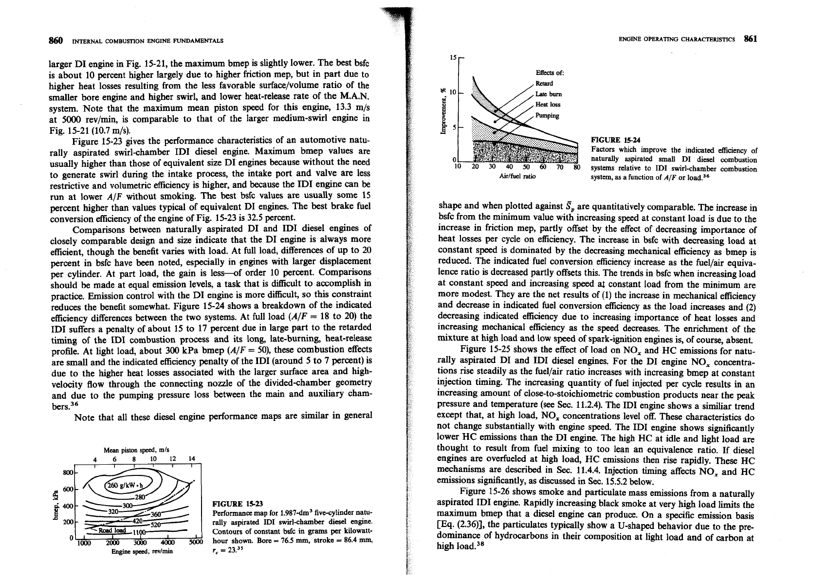
larger DI engine in Fig. 15-21, the maximum bmep is slightly lower. The best bsfc
is about 10 percent higher largely due to higher friction mep, but in part due to
higher heat losses resulting from the less favorable surface/volume ratio of the
smaller bore engine and higher swirl, and lower heat-release rate of the M.A.N.
system. Note that the maximum mean piston speed for this engine, 13.3 m/s
at 5000 revlmin, is comparable to that of the larger medium-swirl engine in
Fig. 15-21 (10.7 m/s).
Figure 15-23 gives the performance characteristics of an automotive natu-
rally aspirated swirl-chamber ID1 diesel engine. Maximum bmep values are
usually higher than those of equivalent size DI engines because without the need
to generate swirl during the intake process, the intake port and valve are less
restrictive and volumetric efficiency is higher, and because the ID1 engine can
be
run at lower
AIF
without smoking. The best bsfc values are usually some 15
percent higher than values typical of equivalent DI engines. The best brake fuel
conversion efficiency of the engine of Fig. 15-23 is 32.5 percent.
Comparisons between naturally aspirated DI and ID1 diesel engines of
closely comparable design and size indicate that the DI engine is always more
efficient, though the benefit varies with load. At full load, differences of up to 20
percent in bsfc have been noted, especially in engines with larger displacement
per cylinder. At part load, the gain is less-of order 10 percent. Comparisons
should be made at equal emission levels, a task that is
dmcult to accomplish in
practice. Emission control with the DI engine is more difficult, so this constraint
reduces the benefit somewhat. Figure 15-24 shows a breakdown of the indicated
efficiency differences between the two systems. At full load (AIF
=
18 to 20) the
ID1 suffers a penalty of about 15 to 17 percent due in large part to the retarded
timing of the ID1 combustion process and its long, late-burning, heat-release
profile. At light load, about 300 kPa bmep (AIF
=
SO), these combustion effects
are small and the indicated efficiency penalty of the ID1 (around 5 to
7
percent) is
due to the higher heat losses associated with the larger surface area and high-
velocity flow through the connecting nozzle of the divided-chamber geometry
and due to the pumping pressure loss between the main and auxiliary cham-
ber~.~~
Note that all these diesel engine performance maps are similar in general
Mean
piston
speed,
mls
4
6
8
10 12
14
FIGURE
15-23
Performance
map
for 1.987-dm3 fivecylinder natu-
rally aspirated
ID1
swirl-chamber diesel engine.
Contours of constant bsfc
in
grams per Kilowatt-
O'
2&
&
-
&
hour shown. Bore
=
76.5
mml
stroke
=
86.4
mm,
Engine
sped,
mrlmin
r,
=
23.35
ENGINE OPERATING
CHARACTERISTICS
861
Effects
of:
,
Retard
F'IGURE
15-24
Factors which improve the indicated efficiency of
naturally aspirated small
DI
diesel combustion
systems relative to
ID1
swirl-chamber combustion
Airlfuel
ratio
system,
as
a function of
A/F
or load.36
shape and when plotted against
S,
are quantitatively comparable. The increase in
bsfc from the minimum value with increasing speed at constant load is due to the
increase in friction mep, partly offset by the effect of decreasing importance of
heat losses per cycle on efficiency. The increase in bsfc with decreasing load at
constant speed is dominated by the decreasing mechanical efficiency as bmep is
reduced. The indicated fuel conversion efficiency increase as the fuellair equiva-
lence ratio is decreased partly offsets this. The trends in bsfc when increasing load
at constant speed and increasing speed
al
constant load from the minimum are
more modest. They are the net results of (1) the increase in mechanical efficiency
and decrease in indicated fuel conversion efficiency as the load increases and (2)
decreasing indicated efficiency due to increasing importance of heat losses and
increasing mechanical efficiency as the speed decreases. The enrichment of the
mixture at high load and low speed of spark-ignition engines is, of course, absent.
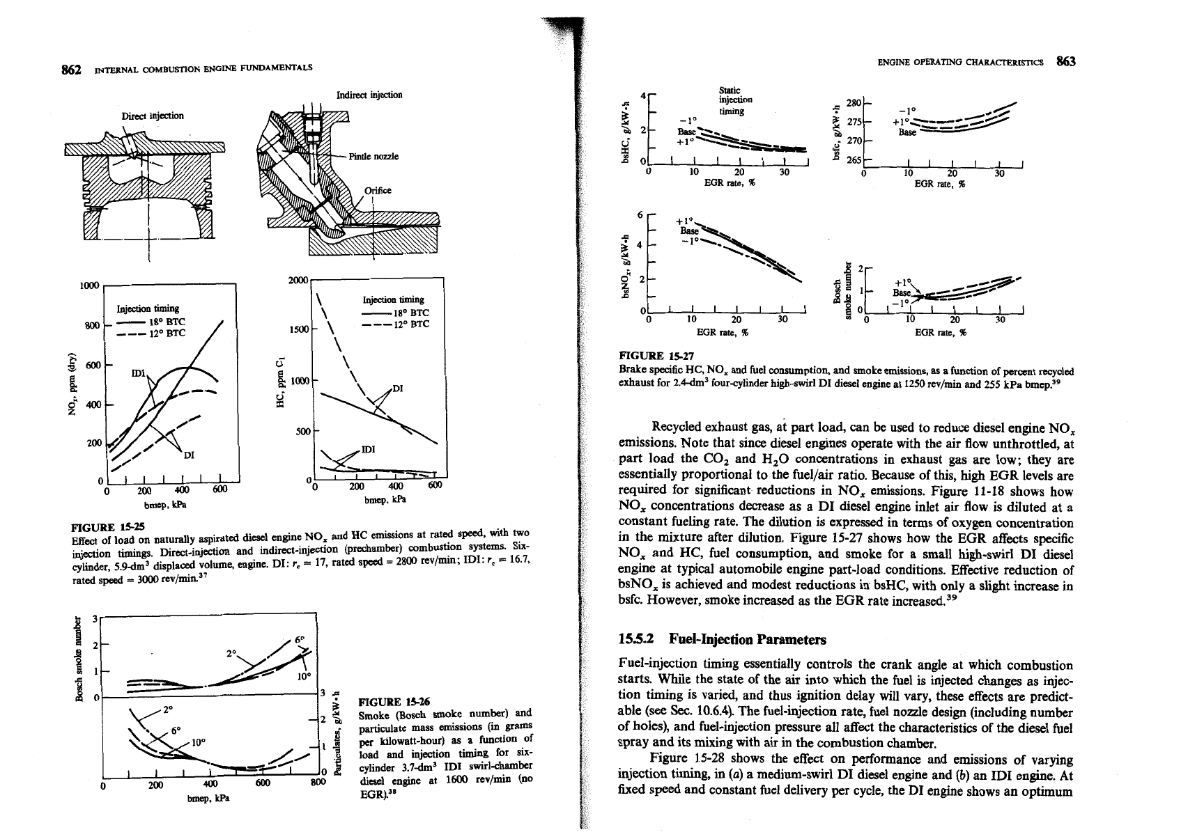
Figure 15-25 shows the effect of load on NO, and HC emissions for natu-
rally aspirated DI and
ID1 diesel engines. For the DI engine NO, concentra-
tions rise steadily as the fuellair ratio increases with increasing bmep at constant
injection timing. The increasing quantity of fuel injected per cycle results in an
increasing amount of close-to-stoichiometric combustion products near the peak
pressure and temperature (see
Sec.
11.2.4). The ID1 engine shows a similiar trend
except that, at high load, NO, concentrations level off. These characteristics do
not change substantially with engine speed. The ID1 engine shows significantly
lower
HC
emissions than the DI engine. The high HC at idle and light load are
thought to result from fuel mixing to too lean an equivalence ratio. If diesel
engines are overfueled at high load, HC emissions then rise rapidly. These HC
mechanisms are described in
Sec. 11.4.4. Injection timing affects NO, and HC
emissions significantly, as discussed in Sec. 15.5.2 below.
Figure 15-26 shows smoke and particulate mass emissions from a naturally
aspirated ID1 engine. Rapidly increasing black smoke at very high load limits the
maximum bmep that a diesel engine can produce. On a specific emission basis
[Eq.
(2.3611, the particulates typically show a U-shaped behavior due to the pre-
dominance of hydrocarbons in their composition at light load and of carbon at
high load.38
Indirect
injection
Direct
injection
Injection
timing
,
-
18'
BTC
12'
BTC
---
/
FIGURE
15-25
1500-
5
Ei
~~-
!i
500
Effect
of load on naturally aspirated diesel engine NO, and
HC
emissions at rated speed,
with
two
injection timings. Direct-injection and indirect-injection @rechamber) combustion systems.
Six-
cvlinder. 5.9dm3 displaced volume, engine. DI:
r,
=
17, rated speed
=
2800
rev/min;
IDI:
r,
=
16.7,
\
Injection timing
\
-
18"
BTC
\
---
120
BTC
\
\
\
-7
yml
\
-
FIGURE
15-26
Smoke
(Bosch
smoke number) and
particulate mass emissions
(in
gram
per
kilowatt-hour) as a function of
load and injection timing for six-
cylinder 3.7dm"DI swirl-chamber
diesel
engine at
1600
rev/min (no
EGR)."
Oo
'2&'4bOYfJ
bmcp,
kPa
timing
EGR
rate,
%
0 10 20 30
EGR
rate,
%
ENGINE
OPERATING
CHARACTERISncS
863
265
20 30
EGR rate.
%
EGR
rate,
%
FIGURE
15-27
Brake specific
HC,
NO, and fuel consumption, and smoke emissions, as a function of perant recycled
exhaust for
2.W3
four-cylinder high-swirl DI diesel engine at
1250
rev/min and 255 kPa brne~.~~
Recycled exhaust gas, at part load, can be used to reduce diesel engine NO,
emissions. Note that since diesel engines operate with the air flow unthrottled, at
part load the
CO, and H,O concentrations in exhaust
gas
are low; they are
essentially proportional to the fuellair ratio. Because of this,
high
EGR levels are
required for significant reductions in NO, emissions. Figure 11-18 shows how
NO, concentrations decrease as a DI diesel engine inlet air flow
is
diluted at a
constant fueling rate. The dilution is expressed in terms of oxygen concentration
in the mixture after dilution. Figure 15-27 shows how the EGR affects specific
NO, and HC, fuel consumption, and smoke for a small high-swirl DI diesel
engine at typical automobile engine part-load conditions. Effective reduction of
bsNO, is achieved and modest reductions in bsHC, with only a slight increase in
bsfc. However, smoke increased
as
the EGR rate increased.3g
155.2
Fuel-Injection
Parameters
Fuel-injection timing essentially controls the crank angle at which combustion
starts. While the state of the
air
into which the fuel is injected changes as injec-
tion timing is varied, and thus ignition delay
will
vary, these effects are predict-
able
(see
See. 10.6.4). The fuel-injection rate, fuel nozzle design (including number
of holes),
and
fuel-injection pressure all affect the characteristics of the diesel fuel
spray and its mixing with
air
in the combustion chamber.
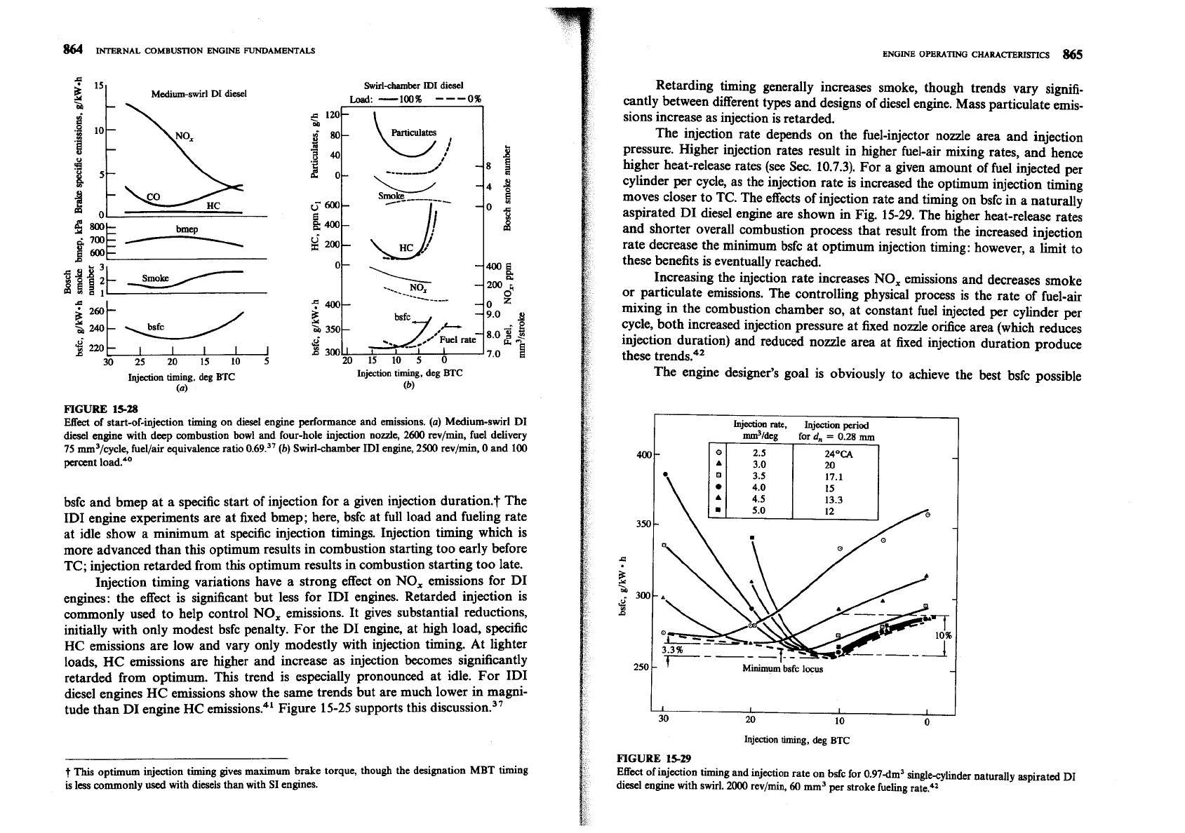
Figure 15-28 shows the effect on performance and emissions of varying
injection
timing,
in
(a)
a medium-swirl DI diesel engine and
(b)
an ID1 engine. At
fixed speed and constant fuel delivery per cycle, the DI engine shows an optimum
Medium-swirl
DI
diesel
Swirlchamber ID1
diesel
Load:-100%
---
0%
Injection timing, deg
BTC
(a)
Injection timing, deg
BTC
(b)
FIGURE
15-28
Effect of start-of-injection timing on diesel engine performance and emissions.
(a)
Medium-swirl
DI
diesel engine with deep combustion bowl and four-hole injection nozzle,
2600
rev/min, fuel delivery
75
mm3/cycle, fuellair equivalence ratio 0.69.37
(b)
Swirl-chamber
ID1
engine,
2500
rev/min,
0
and
100
percent
bsfc and bmep at a specific start of injection for a given injection duration.? The
ID1 engine experiments are at fixed bmep; here, bsfc at full load and fueling rate
at idle show a minimum at specific injection timings. Injection timing which is
more advanced than this optimum results in combustion starting too early before
TC; injection retarded from this optimum results in combustion starting too late.
Injection timing variations have a strong effect on NO, emissions for DI
engines: the effect is significant but less for
ID1 engines. Retarded injection is
commonly used to help control NO, emissions. It gives substantial reductions,
initially with only modest bsfc penalty. For the DI engine, at high load, specific
HC emissions are low and vary only modestly with injection timing. At lighter
loads, HC emissions are higher and increase as injection becomes significantly
retarded from optimum. This trend is especially pronounced at idle. For ID1
diesel engines HC emissions show the same trends but are much lower in magni-
tude than DI engine HC
emission^.^'
Figure 15-25 supports this di~cussion.~'
-
-
This optimum injection timing gives maximum brake torque, though the designation MBT timing
is
less commonly used with diesels than with
SI
engines.
Retarding timing generally increases smoke, though trends vary signifi-
cantly between different types and designs of diesel engine. Mass particulate emis-
sions increase
as
injection is retarded.
The injection rate depends on the fuel-injector nozzle area and injection
pressure. Higher injection rates result in higher fuel-air mixing rates, and hence
higher heat-release rates (see
Sec. 10.7.3). For a given amount of fuel injected per
cylinder per cycle, as the injection rate is increased the optimum injection timing
moves closer to TC. The effects of injection rate and timing on bsfc in a naturally
aspirated DI diesel engine are shown in Fig. 15-29. The higher heat-release rates
and shorter overall combustion process that result from the increased injection
rate decrease the minimum bsfc at optimum injection timing: however,
a
limit to
these benefits is eventually reached.
Increasing the injection rate increases NO, emissions and decreases smoke
or particulate emissions. The controlling physical process is the rate of fuel-air
mixing in the combustion chamber so, at constant fuel injected per cylinder per
cycle, both increased injection pressure at fixed nozzle orifice area (which reduces
injection duration) and reduced nozzle area at fixed injection duration produce
these trends.42
The engine designer's goal is obviously to achieve the best bsfc possible
250
t
'
Minimum
bsfc
locus
400-
I
I
I
I
30 20 10
0
Injection timing, deg
BTC
FIGURE
15-29
Effect of injection timing and injection rate on bsfc for 0.97dm3 single-cylinder naturally aspirated
DI
diesel engine with swirl.
2000
rev/min,
60
mm3 per stroke fueling rate.*=
Injection
rate,
Injection
period
mm3/deg
for
d,,
=
0.28
mm
0
2.5
3.0
24OCA
20
-
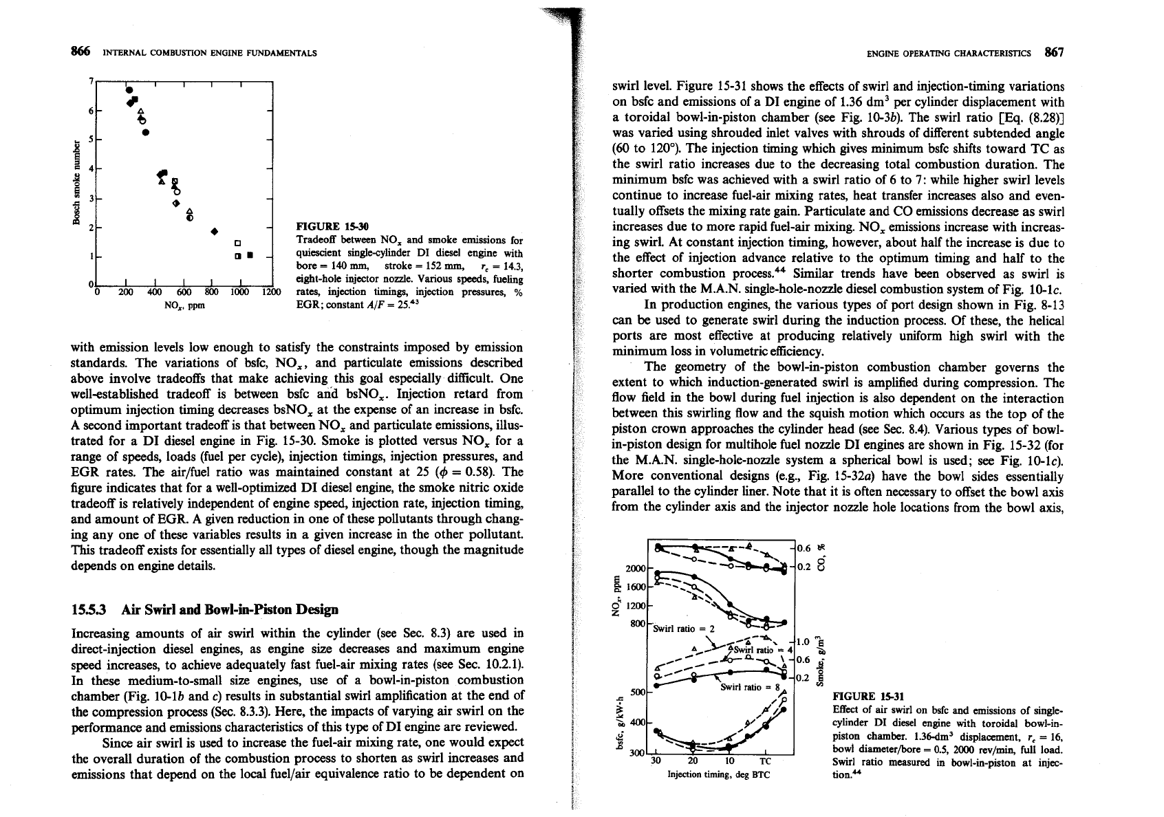
FIGURE
15-30
Tradeoff between
NO,
and smoke emissions for
quiescient single-cylinder
DI
diesel engine
with
bore
=
140
mm,
stroke
=
152
mm,
r,
=
14.3,
eight-hole injector node. Various speeds, fueling
rates, injection timings, injection pressures,
%
EGR;
constant
AIF
=
25.43
with emission levels low enough to satisfy the constraints imposed by emission
standards. The variations of bsfc, NO,, and particulate emissions described
above involve tradeoffs that make achieving this goal especially difficult. One
well-established
tradeoff is between bsfc and bsNO,. Injection retard from
optimum injection timing decreases bsNO, at the expense of an increase in bsfc.
A second important tradeoff is that between NO, and particulate emissions, illus-
trated for a DI diesel engine in Fig. 15-30. Smoke is plotted versus NO, for a
range of speeds, loads (fuel per cycle), injection timings, injection pressures, and
EGR
rates. The air/fuel ratio was maintained constant at 25
(4
=
0.58). The
figure indicates that for a well-optimized DI diesel engine, the smoke nitric oxide
tradeoff is relatively independent of engine speed, injection rate, injection timing,
and amount of
EGR.
A given reduction in one of these pollutants through chang-
ing any one of these variables results in a given increase in the other pollutant.
This
tradeoff exists for essentially all types of diesel engine, though the magnitude
depends on engine details.
155.3
Air
Swirl
and
Bowl-in-Piston
Design
Increasing amounts of air swirl within the cylinder (see Sec. 8.3) are used in
direct-injection diesel engines, as engine size decreases and maximum engine
speed increases, to achieve adequately fast fuel-air mixing rates (see Sec. 10.2.1).
In these medium-to-small size engines, use of a bowl-in-piston combustion
chamber (Fig. 10-lb and
c)
results in substantial swirl amplification at the end of
the compression process (Sec. 8.3.3). Here, the impacts of varying air swirl on the
performance and emissions characteristics of this type of DI engine are reviewed.
Since air swirl is used to increase the fuel-air mixing rate, one would expect
the overall duration of the combustion process to shorten as swirl increases and
emissions that depend on the local
fuelfair equivalence ratio to be dependent on
ENGINE
OPERATING
CHARACTERISTICS
867
swirl level. Figure 15-31 shows the effects of swirl and injection-timing variations
on bsfc and emissions of a DI engine of 1.36 dm3 per cylinder displacement with
a toroidal bowl-in-piston chamber (see Fig. 10-3b). The swirl ratio [Eq.
(8.2811
was varied using shrouded inlet valves with shrouds of different subtended angle
(60
to 120"). The injection timing which gives minimum bsfc shifts toward TC as
the swirl ratio increases due to the decreasing total combustion duration. The
minimum bsfc was achieved with a swirl ratio of 6 to
7:
while higher swirl levels
continue to increase fuel-air mixing rates, heat transfer increases also and even-
tually offsets the mixing rate gain. Particulate and CO emissions decrease as swirl
increases due to more rapid fuel-air mixing. NO, emissions increase with increas-
ing swirl. At constant injection timing, however, about half the increase is due to
the effect of injection advance relative to the optimum timing and half to the
shorter combustion
process.44 Similar trends have been observed as swirl is
varied with the M.A.N. single-hole-nozzle diesel combustion system of Fig. 10-lc.
In production engines, the various types of port design shown in Fig. 8-13
can be used to generate swirl during the induction process. Of these, the helical
ports are most effective at producing relatively uniform high swirl with the
minimum loss in volumetric efficiency.
The geometry of the bowl-in-piston combustion chamber governs the
extent to which induction-generated swirl is amplified during compression. The
flow field in the bowl during fuel injection is also dependent on the interaction
between this swirling flow and the squish motion which occurs as the top of the
piston crown approaches the cylinder head (see
Sec.
8.4).
Various types of bowl-
in-piston design for multihole fuel nozzle DI engines are shown in Fig. 15-32 (for
the
M.A.N.
single-hole-nozzle system a spherical bowl is used; see Fig. 10-lc).
More conventional designs (e.g., Fig. 15-32a) have the bowl sides essentially
parallel to the cylinder liner. Note that it is often necessary to offset the bowl axis
from the cylinder axis and the injector nozzle hole locations from the bowl axis,
FIGURE
1-1
Effect
of air swirl on bsfc and emissions of single-
cylinder
DI
diesel engine
with
toroidal bowl-in-
&
piston chamber. 1.36-dm3 displacement,
r,
=
16,
B
300
bowl diameter/bore
=
0.5,
2000
rev/min,
full load.
30
20
10
TC
Swirl ratio measured in bowl-in-piston at injec-
Injection timing, deg
BTC
ti~n.~
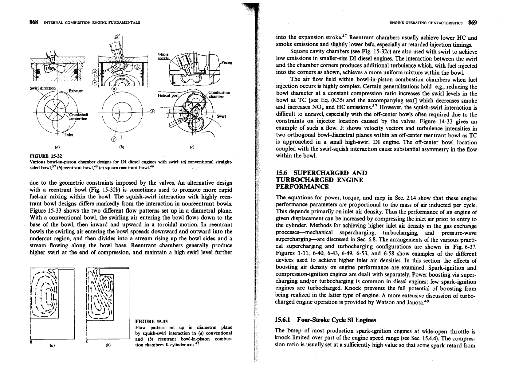
4-hole
nozzle
Piston
(0)
(b)
(4
FIGURE 15-32
Various bowl-in-piston chamber designs for
DI
diesel engines
with
swirl:
(a)
conventional
straight-
sided bowl:7
(b)
reentrant bowlp5
(c)
square reentrant bowl.46
due to the geometric constraints imposed by the valves. An alternative design
with a reentrant bowl (Fig. 15-32b) is sometimes used to promote more rapid
fuel-air mixing within the bowl. The squish-swirl interaction with highly reen-
trant bowl designs differs markedly from the interaction in nonreentrant bowls.
Figure 15-33 shows the two different flow patterns set up in a diametral plane.
With a conventional bowl, the swirling air entering the bowl flows down to the
base of the bowl, then inward and upward in a toroidal motion. In reentrant
bowls the swirling air entering the bowl spreads downward and outward into the
undercut region, and then divides into a stream rising up the bowl sides and a
stream flowing along the bowl base. Reentrant chambers generally produce
higher swirl at the end of compression, and maintain a high swirl level further
FIGURE
15-33
Flow pattern set up in diametral plane
by
squish-swirl interaction in
(a)
conventional
C
t
and
(b)
reentrant bowl-in-piston combus-
(a) (b)
tion chambers.
E
cylinder axis.47
into the expansion stroke.q7 Reentrant chambers usually achieve lower HC and
smoke emissions and slightly lower bsfc, especially at retarded injection timings.
Square cavity chambers (see Fig.
15-32c) are also used with swirl to achieve
low emissions in smaller-size DI diesel engines. The interaction between the swirl
and the chamber comers produces additional turbulence which, with fuel injected
into the corners as shown, achieves a more uniform mixture within the bowl.
The air flow field within bowl-in-piston combustion chambers when fuel
injection occurs is highly complex. Certain generalizations hold: e.g., reducing the
bowl diameter at a constant compression ratio increases the swirl levels in the
bowl at TC [see
Eq.
(8.35) and the accompanying text] which decreases smoke
and increases
NO,
and
HC
emissions.37 However, the squish-swirl interaction is
difficult to unravel, especially with the off-center bowls often required due to the
constraints on injector location caused by the valves. Figure 14-33 gives an
example of such a flow.
It
shows velocity vectors and turbulence intensities in
two orthogonal bowl-diametral planes within an off-center reentrant bowl as TC
is approached in a small high-swirl DI engine. The off-center bowl location
coupled with the swirl-squish interaction cause substantial asymmetry in the flow
within the bowl.
15.6 SUPERCHARGED
AND
TURBOCHARGED ENGINE
PERFORMANCE
The equations for power, torque, and mep in Sec. 2.14 show that these engine
performance parameters are proportional to the mass of air inducted per cycle.
This depends primarily on inlet air density. Thus the performance of an engine of
given displacement can be increased by compressing the inlet air prior to entry to
the cylinder. Methods for achieving higher inlet air density in the gas exchange
processes-mechanical supercharging, turbocharging, and pressure-wave
supercharging-are discussed in
Sec. 6.8. The arrangements of the various practi-
cal supercharging and turbocharging configurations are shown
in
Fig. 6-37.
Figures 1-11, 6-40, 6-43,
6-49,
6-53, and 6-58 show examples of the different
devices used to achieve higher inlet air densities. In this section the effects of
boosting air density on engine performance are examined. Spark-ignition and
compression-ignition engines are dealt with separately. Power boosting via super-
charging and/or turbocharging is common in diesel engines: few spark-ignition
engines are turbocharged. Knock prevents the full potential of boosting from
being realized in the latter type of engine. A more extensive discussion of turbo-
charged engine operation is provided by Watson and
Jan~ta.~~
15.6.1 Four-Stroke Cycle SI
Engines
The bmep of most production spark-ignition engines at wide-open throttle is
knock-limited over part of the engine speed range (see Sec. 15.4.4). The compres-
sion ratio is usually set at a sufficiently high value so that some spark retard from
