Heywood J.B. Internal Combustion Engines Fundamentals
Подождите немного. Документ загружается.

n
Turbocharger
w
8
Inter
wa84gate
AP
I
1
7
4
5
1244
6
-
7
-
Intake
-
Multicylinder
-
Exhaust
manifold
-
diesel
engine
-
manifold
-
-
Q
f
Engine
friction
FIGURE
14-24
Block diagram
of
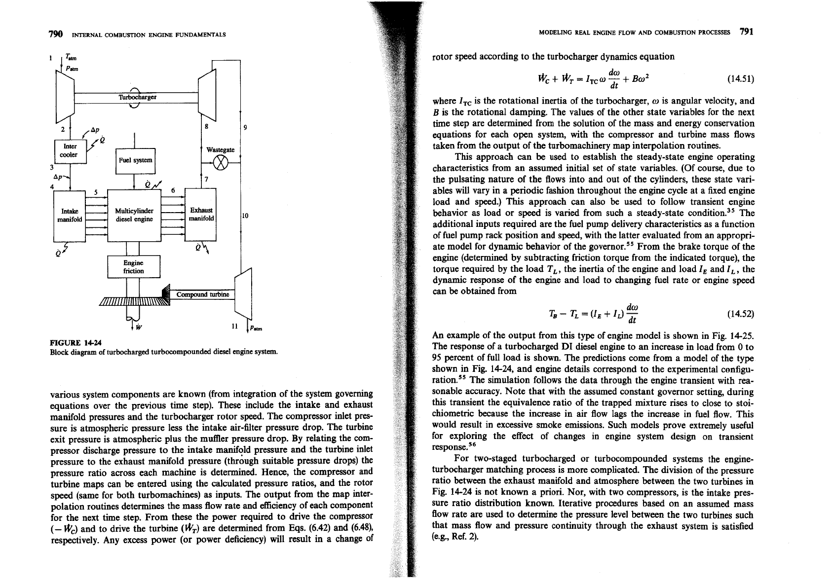
turbocharged turbocompounded diesel engine system.
various system components are known (from integration of the system governing
equations over the previous time step). These include the intake and exhaust
manifold pressures and the turbocharger rotor speed. The compressor inlet pres-
sure is atmospheric pressure less the intake air-filter pressure drop.
The turbine
exit pressure is atmospheric plus the muffler pressure drop. By relating the com-
pressor discharge pressure to the intake manifqld pressure and the turbine inlet
pressure to the exhaust manifold pressure (through suitable pressure drops) the
pressure ratio across each machine is determined. Hence, the compressor and
turbine maps can be entered using the calculated pressure ratios, and the rotor
speed (same for both turbomachines) as inputs. The output from the map inter-
polation routines determines the mass flow rate and efficiency of each component
for the next time step. From these the power required to drive the compressor
(-
wc) and to drive the turbine (wT) are determined from Eqs. (6.42) and (6.48),
respectively. Any excess power (or power deficiency) will result
in
a change of
rotor speed according to the turbocharger dynamics equation
where
ITc
is the rotational inertia of the turbocharger,
o
is angular velocity, and
B
is the rotational damping. The values of the other state variables for the next
time step are determined from the solution of the mass and energy conservation
equations for each open system, with the compressor and turbine mass flows
taken from the output of the turbomachinery map interpolation routines.
This approach can be used to establish the steady-state engine operating
characteristics from an assumed initial set of state variables. (Of course, due to
the pulsating nature of the flows into and out of the cylinders, these state vari-
ables will vary in a periodic fashion throughout the engine cycle at a fixed engine
load and speed.)
This approach can also be used to follow transient engine
behavior as load or speed is varied from such a steady-state condition.35 The
additional inputs required are the fuel pump delivery characteristics as a function
of fuel pump rack position and speed, with the latter evaluated from an appropri-
ate model for dynamic behavior of the
g~vernor.'~ From the brake torque of the
engine (determined by subtracting friction torque from the indicated torque), the
torque required by the load
TL
,
the inertia of the engine and load
I,
and
I,,
the
dynamic response of the engine and load to changing fuel rate or engine speed
can be obtained from
An
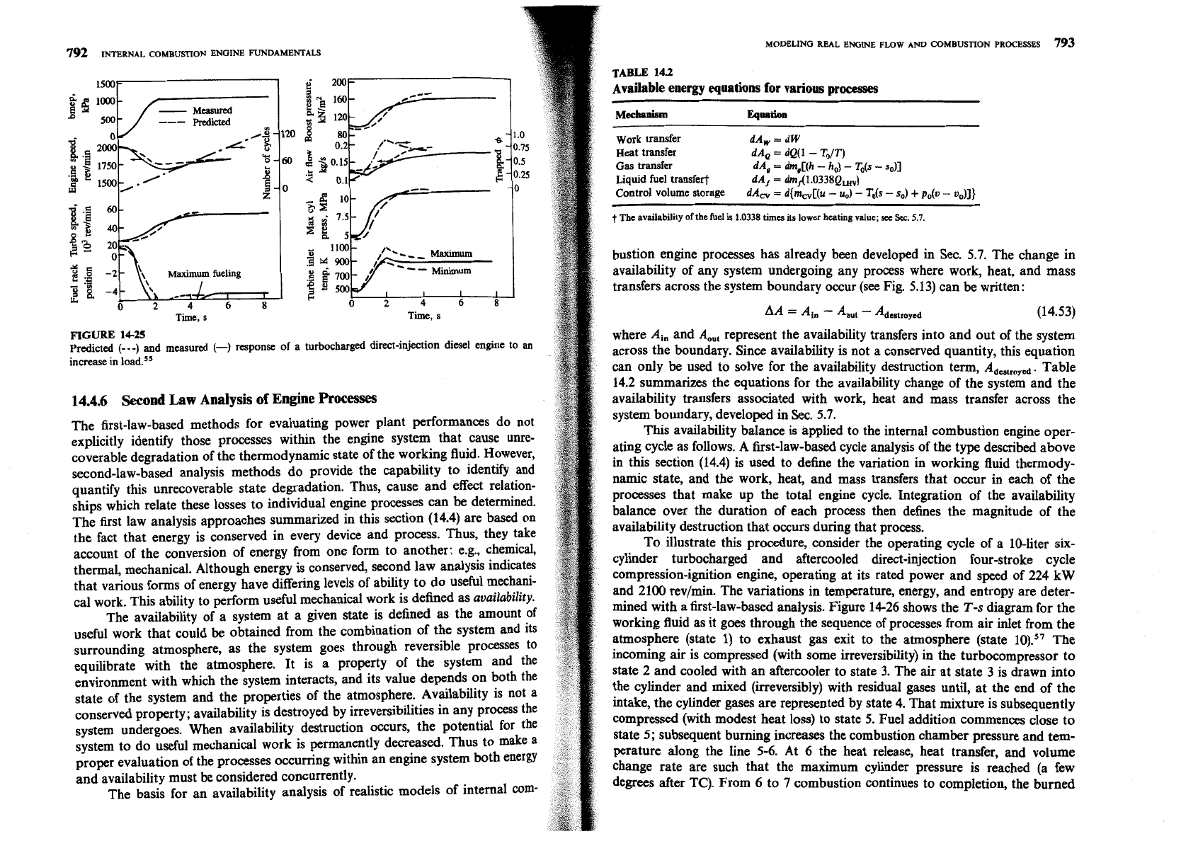
example of the output from this type of engine model is shown in Fig. 14-25.
The response of a turbocharged
DI
diesel engine to an increase in load from
0
to
95
percent of full load is shown. The predictions come from a model of the type
shown in Fig. 14-24, and engine details correspond to the experimental configu-
ration.55 The simulation follows the data through the engine transient with rea-
sonable accuracy. Note that with the assumed constant governor setting, during
this transient the equivalence ratio of the trapped mixture rises to close to
stoi-
chiometric because the increase in air flow lags the increase in fuel flow. This
would result in excessive smoke emissions. Such models prove extremely useful
for exploring the effect
of changes in engine system design on transient
response.56
For two-staged turbocharged or turbocompounded systems the engine-
turbocharger matching process is more complicated. The division of the pressure
ratio between the exhaust manifold and atmosphere between the two turbines in
Fig. 14-24 is not known a priori. Nor, with two compressors, is the intake pres-
sure ratio distribution known. Iterative procedures based on an assumed mass
flow rate are used to determine the pressure level between the two turbines such
that mass flow and pressure continuity through the exhaust system is satisfied
(e.g., Ref. 2).
792
INTERNAL COMBUSTION ENGINE FUNDAMENTALS
MODELING REAL ENGINE FLOW
AND
COMBUSTION PROCESSES
793
1500'
TABLE
143
Available energy equations for various
processes
-
Measured
MeehPnism
Eqllntioo
Work transfer
dA,
=
dW
Heat transfer
dAQ
=
dQ(1
-
To/T)
Gas transfer
dA,
=
dm,[(h
-
h,)
-
To(s
-
so)]
Liquid fuel transfert
dA,
=
dm,-(1.O338Qw)
Control volume storage
dA,
=
d{m,[(u
-
u,)
-
To(s
-
so)
+
p,(v
-
v,)]}
t
The
availability
of
the
he1
is
1.0338
times
its
lower
heating
value;
see
Sec.
5.7.
bustion engine processes has already been developed in Sec. 5.7. The change in
availability of any system undergoing any process where work, heat, and mass
transfers across the system boundary occur (see Fig. 5.13) can be written:
Tie,
s
Ti,
s
AA
=
-
-
Adcstroycd
(14.53)
FIGURE
14-25
where
A,,,
and
A,,,
represent the availability transfers into and out of the system
Predicted
(---)
and measured
(-1
response of
a
turbocharged direct-injection diesel engine to an
increase in load.5s
across the boundary. Since availability is not a conserved quantity, this equation
can only be used to solve for the availability destruction term,
AdeStmye,.
Table
14.2 summarizes the equations for the availability change of the system and the
14.4.6
Second
Law
Analysis
of
Engine
Processes
availability transfers associated with work, heat and mass transfer across the
The first-law-based methods for evaluating power plant performances do not
system boundary, developed
in
Sec. 5.7.
explicitly identify those processes within the engine system that cause unre-
This availability balance is applied to the internal combustion engine oper-
coverable degradation of the thermodynamic state of the working fluid. However,
ating cycle as follows. A first-law-based cycle analysis of the type described above
second-law-based analysis methods do provide the capability to identify and
in this section (14.4) is used to define the variation in working fluid
themody-
quantify this unrecoverable state degradation. Thus, cause and effect relation-
namic state, and the work, heat, and mass transfers that occur
in
each of the
ships which relate these losses to individual engine processes can be determined.
processes that make up the total engine cycle. Integration of the availability
The first law analysis approaches summarized in this section (14.4) are based on
balance over the duration of each process then defines the magnitude of the
the fact that energy is conserved in every device and Process.
Thus, they take
availability destruction that occurs during that process.
account of the conversion of energy from one form to another: e.g., chemical,
To illustrate this procedure, consider the operating cycle of a 10-liter six-
thermal, mechanical. Although energy is conserved, second law analysis indicates
cylinder turbocharged and aftercooled direct-injection four-stroke cycle
that various forms of energy have differing levels of ability to do useful mechani-
compression-ignition engine, operating at its rated power and speed of 224 kW
cal work. This ability to perform useful mechanical work is defined as
availability.
and 2100 rev/min. The variations in temperature, energy, and entropy are deter-
The availability of a system at a given state is defined
as
the amount of
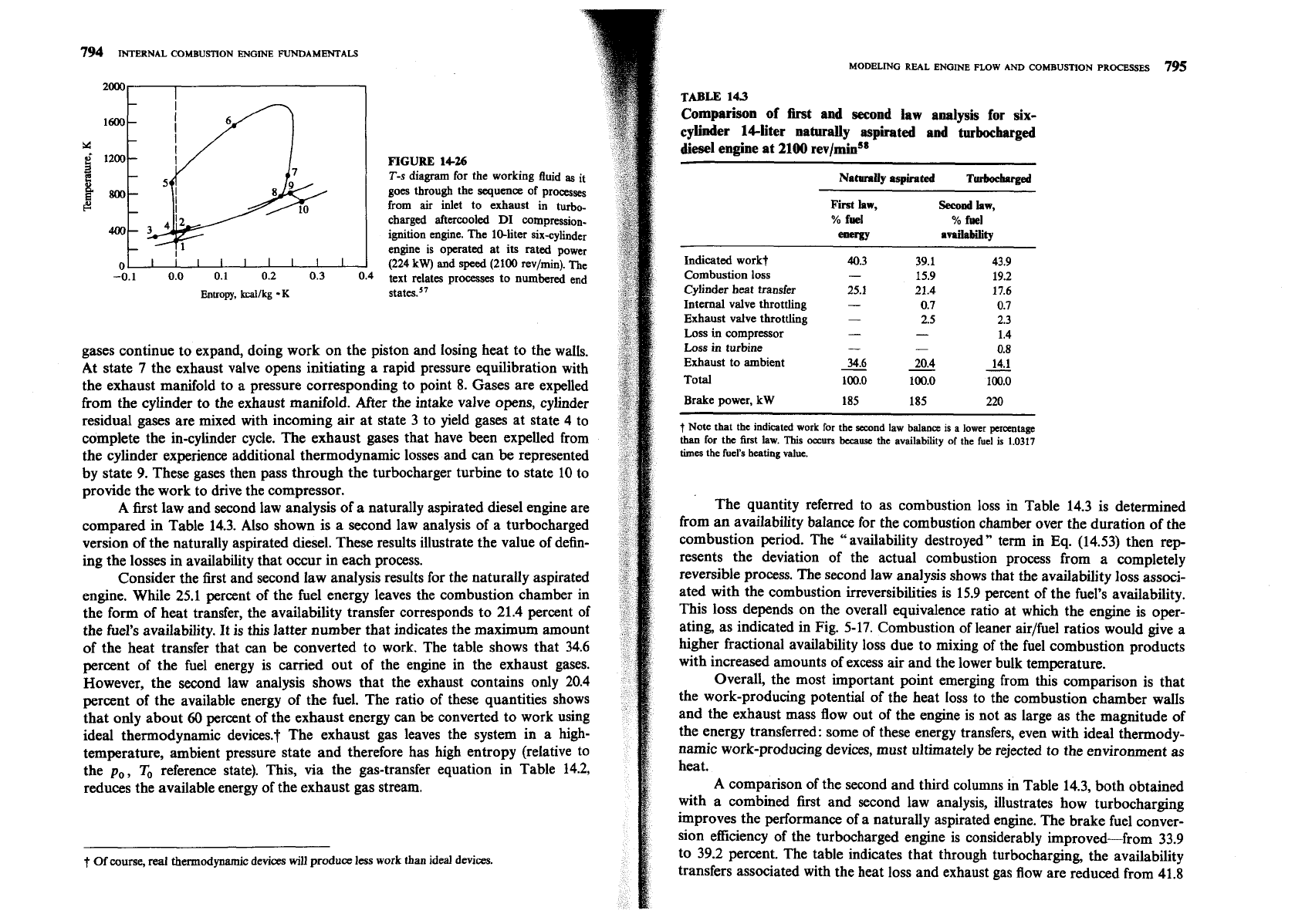
mined with a first-law-based analysis. Figure 14-26 shows the
T-s
diagram for the
useful work that could be obtained from the combination of the system and its
working fluid as it goes through the sequence of processes from air inlet from the
surrounding atmosphere, as the system goes through reversible processes to
atmosphere (state
1)
to exhaust gas exit to the atmosphere (state
The
equilibrate with the atmosphere. It is a property of the system and the
incoming air is compressed (with some irreversibility) in the turbocompressor to
environment with which the system interacts, and its value depends on both the
state 2 and cooled with an aftercooler to state 3. The air at state 3 is drawn into
state of the system and the properties of the atmosphere. Availability is not a
the cylinder and mixed (irreversibly) with residual gases until, at the end of the
conserved property; availability is destroyed by irreversibilities in any process the
intake, the cylinder gases are represented by state 4. That mixture is subsequently
system undergoes. When availability destruction occurs, the potential for
the
compressed (with modest heat loss) to state 5. Fuel addition commences close to
system to do useful mechanical work is permanently decreased.
Thus
to make a
state 5; subsequent burning increases the combustion chamber pressure and
tern-
proper evaluation of the processes occurring within an engine system both energy
perature along the line 5-6. At 6 the heat release, heat transfer, and volume
and availability must be considered concurrently.
change rate are such that the maximum cylinder pressure is reached (a few
The basis for an availability analysis of realistic models of intexd corn-
degrees after TC). From 6 to
7
combustion continues to completion, the burned
794
INTERNAL COMBUSTION ENGME FUNDAMENTALS
20001
1
Entropy,
kcallkg
K
FIGURE
14-26
T-s
diagram for the working fluid
as
it
goes through the
sequence
of processes
from air inlet to exhaust in turbo-
charged aftercooled
DI
compression-
ignition engine. The 10-liter six-cylinder
engine is operated at its
rated
power
(224
kW)
and speed (2100 rev/min). The
text relates processes to numbered end
gases continue to expand, doing work on the piston and losing heat to the walls.
At state
7
the exhaust valve opens initiating a rapid pressure equilibration with
the exhaust manifold to a pressure corresponding to point
8.
Gases are expelled
from the cylinder to the exhaust manifold. After the intake valve opens, cylinder
residual gases are mixed with incoming air at state
3
to yield gases at state
4
to
complete the in-cylinder cycle. The exhaust gases that have been expelled from
the cylinder experience additional thermodynamic losses and can be represented
by state
9.
These gases then pass through the turbocharger turbine to state
10
to
provide the work to drive the compressor.
A
first law and second law analysis of a naturally aspirated diesel engine are
compared in Table
14.3.
Also shown is a second law analysis of a turbocharged
version of the naturally aspirated diesel. These results illustrate the value of defin-
ing the losses in availability that occur in each process.
Consider the first and second law analysis results for the naturally aspirated
engine. While
25.1
percent of the fuel energy leaves the combustion chamber in
the form of heat transfer, the availability transfer corresponds to
21.4
percent of
the fuel's availability. It is this latter number that indicates the maximum amount
of the heat transfer that can be converted to work. The table shows that
34.6
percent of the fuel energy is carried out of the engine in the exhaust gases.
However, the second law analysis shows that the exhaust contains only
20.4
percent of the available energy of the fuel. The ratio of these quantities shows
that only about
60
percent of the exhaust energy can
be
converted to work using
ideal thermodynamic devices.? The exhaust gas leaves the system in a high-
temperature, ambient pressure state and therefore has high entropy (relative to
the
po,
To reference state). This, via the gas-transfer equation in Table
14.2,
reduces the available energy of the exhaust gas stream.
t
Of
course, real thennodynamic devices
will
produce less work than ideal devices.
MODELING REAL ENGINE FLOW AND COMBUSTION PROCESSES
795
TABLE
143
Comparison of first and second law analysis for six-
cylinder 14-liter naturally aspirated and -mbocbarged
diesel engine at 2100 rev/mins8
NatnraUy
aspirated
Turboehvged
First
law,
%
fuel
energy
Second
hw,
%
fwl
availability
Indicated work?
Combustion loss
Cylinder heat transfer
Internal valve throttling
Exhaust valve throttling
Loss
in
compressor
Loss
in
turbine
Exhaust to ambient
Total
Brake power,
kW
185 185 220
-
f
Note that the indicated work for the second law
balance
is a lower
percentage
than
for
the
first law. This occurs
because
the availability of the fuel
is
1.0317
times the fuel's heating value.
The quantity referred to as combustion loss in Table
14.3
is determined
from an availability balance for the combustion chamber over the duration of the
combustion period. The "availability destroyed" term in
Eq.
(14.53)
then rep-
resents the deviation of the actual combustion process from a completely
reversible process. The second law analysis shows that the availability loss associ-
ated with the combustion irreversibilities is
15.9
percent of the fuel's availability.
This loss depends on the overall equivalence ratio at which the engine is oper-
ating, as indicated in Fig.
5-17.
Combustion of leaner airlfuel ratios would give a
higher fractional availability loss due to mixing of the fuel combustion products
with increased amounts of excess air and the lower bulk temperature.
Overall, the most important point emerging from this comparison is that
the work-producing potential of the heat loss to the combustion chamber walls
and the exhaust mass flow out of the engine is not
as
large as the magnitude of
the energy transferred: some of these energy transfers, even with ideal thermody-
namic work-producing devices, must ultimately
be
rejected to the environment as
heat.
A comparison of the second and third columns in Table
14.3,
both obtained
with a combined first and second law analysis, illustrates how turbocharging
improves the performance of a naturally aspirated engine. The brake fuel conver-
sion efficiency of the turbocharged engine is considerably improved-from
33.9
to
39.2
percent. The table indicates that through turbocharging, the availability
transfers associated with the heat loss and exhaust gas flow are reduced from
41.8
7%
INTERNAL COMBUSTION ENGINE FUNDAMENTALS
to 31.7 percent (a difference of 10.1 percentage points), while the combustion and
added turbomachinery availability losses increase from 15.9 to 21.4 percent (a
difference of 5.5 percentage points). By turbocharging, advantage has been taken
of the following changes. While the leaner air/fuel ratio operation of the turbo.
charged engine increases the combustion availability losses due to the use of a
greater portion of the chemical energy of the fuel to mix with and heat excess air,
the lower burned gas temmrature this produces results in reduced heat losses and
-
lower cvlinder exhaust temperature. ~naddition, the turbocharger transfers avail-
able energy from the cylinder exhaust to the inlet air. The reduced heat loss and
lower final exhaust availability level give a substantial performance improve-
ment."
To interpret the second law analysis results, one must remember that the
desired output is brake work and increases in this quantity (for a given fuel flow)
represent improved performance. All other availability terms represent losses
or
undesirable transfers from the system; decreasing these terms constitutes an
improvement. These undesirable available energy transfer and destruction terms
fall into five categories:
(1)
heat transfer, (2) combustion,
(3)
fluid flow,
(4)
exhaust
to ambient, (5) mechanical friction. The available energy flows identified as heat
transfer represent the summation of all availability transfers that occur due to
heat transfers. The most significant of these are the in-cylinder and aftercooler
heat rejection. The combustion loss represents the amount of available energy
destroyed due to irreversibilities occurring in releasing the chemical potential of
the fuel as thermal energy and mixing the combustion products with any excess
air. The fluid flow losses include the available energy destroyed within the
working fluid in the compressor, aftercooler, intake valve, exhaust valve, exhaust
manifold, and turbine due to fluid shear and throttling. The availability
destroyed due to fluid shear and mechanical rubbing, exterior to the working
fluid, are contained in the mechanical friction category. The effect of variations in
engine load and speed on these five categories of losses or transfers will now
be
described.
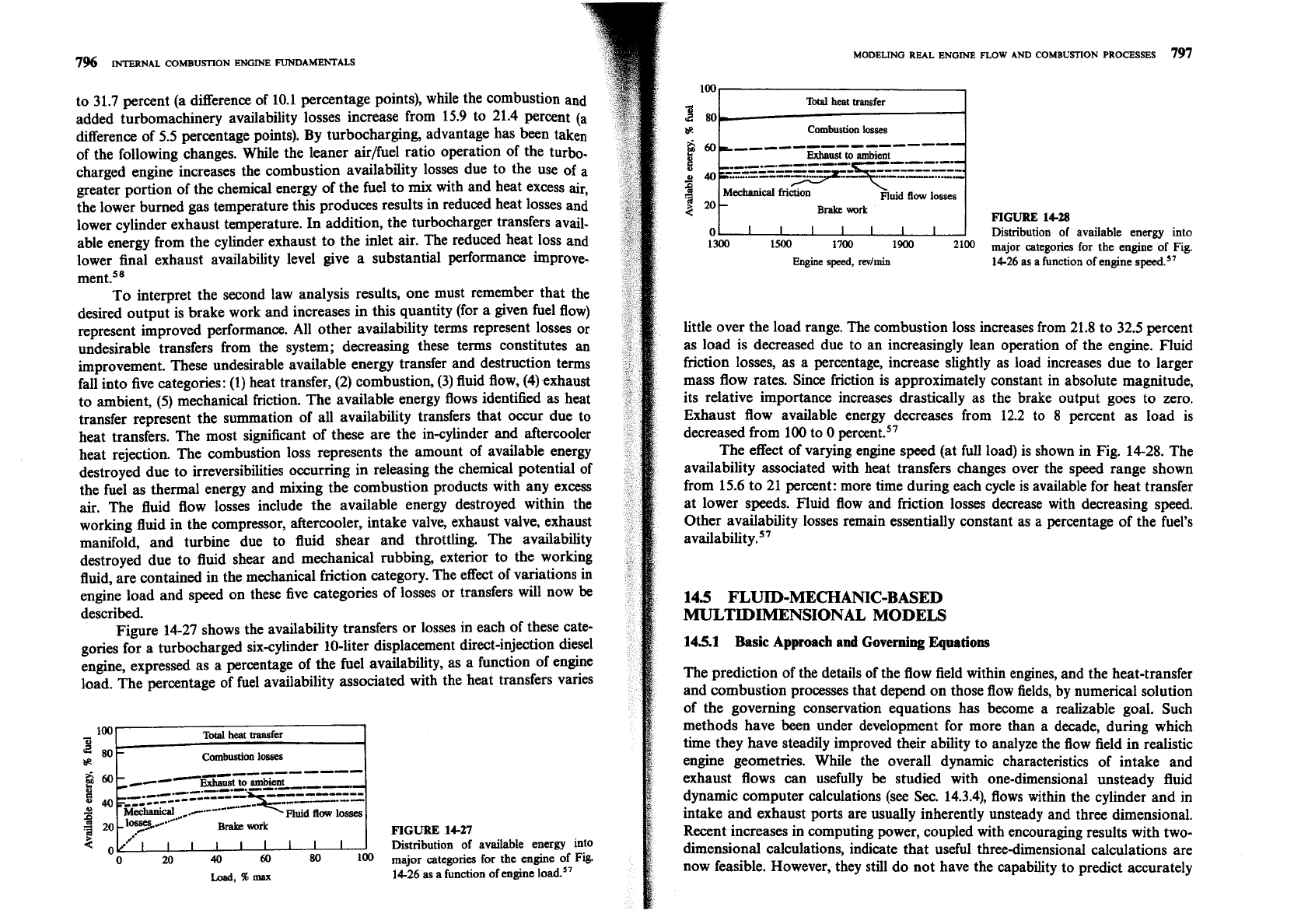
Figure 14-27 shows the availability transfers or losses in each of these cate-
gories for a turbocharged six-cylinder 10-liter displacement direct-injection diesel
engine, expressed as a percentage of the fuel availability, as a function of engine
load. The percentage of fuel availability associated with the heat transfers varies
Fluid
flow
losses
Brake
work
FIGURE
14-27
100
3
80-
BR
ZO~lllll'r I'
..-.
Distribution of available energy into
0
20
40
60
80
100
major categories
for
the engine of Fig.
Losd,%max
14-26
as
a function of engine load."
Total
heat
transfer
Combustion
losses
MODELING REAL ENGINE FLOW AND COMBUSTION PROCESSES
797
100
+
Total
heat
transfer
d
80
Combustion
losses
nuid
flow
losses
Brake
wrk
FIGURE
14-28
0
1
I
I
I I
I
I
I
I
Distribution of available energy into
1300
150 1700
1900
2100
major categories for the engine of Fig.
Engine
speed,
revlmin
14-26 as
a
function
of
engine speed.57
little over the load range. The combustion loss increases from 21.8 to 32.5 percent
as load is decreased due to an increasingly lean operation of the engine. Fluid
friction losses, as a percentage, increase slightly as load increases due to larger
mass flow rates. Since friction is approximately constant in absolute magnitude,
its relative importance increases drastically as the brake output goes to zero.
Exhaust flow available energy decreases from 12.2 to 8 percent as load is
decreased from 100 to
0 percent.''
The effect of varying engine speed (at full load) is shown in Fig. 1428. The
availability associated with heat transfers changes over the speed range shown
from 15.6 to 21 percent: more time during each cycle is available for heat transfer
at lower speeds. Fluid flow and friction losses decrease with decreasing speed.
Other availability losses remain essentially constant as a percentage of the fuel's
availability.
57
145
FLUID-MECHANIC-BASED
MULTIDIMENSIONAL MODELS
14.5.1 Basic Approach
and
Governing
Equations
The prediction of the details of the flow field within engines, and the heat-transfer
and combustion processes that depend on those flow fields, by numerical solution
of the governing conservation equations has become a realizable goal. Such
methods have been under development for more than a decade, during which
time they have steadily improved their ability to analyze the flow field in realistic
engine geometries. While the overall dynamic characteristics of intake and
exhaust flows can usefully be studied with one-dimensional unsteady fluid
dynamic computer calculations (see
Sec. 14.3.4), flows within the cylinder and in
intake and exhaust ports are usually inherently unsteady and three dimensional.
Recent increases in computing power, coupled with encouraging results with two-
dimensional calculations, indicate that useful three-dimensional calculations are
now feasible. However, they still do not have the capability to predict accurately
798
INTERNAL
COMBUSTION
ENGINE
FUNDAMENTALS
all the features of real engine processes of interest. Gas-flow patterns can be pre.
dicted best; predictions of fuel spray behavior are less complete, and combustion
calculations
mesent considerable difficulties.
These lomputational, fluid dynamic, engine process analysis codes solve the
partial differential equations for conservation of mass, momentum, energy, and
species concentrations. To apply a digital computer to the solution of a contin-
uum problem (such as the flow field inside the cylinder), the continuum must
be
represented by a finite number of discrete elements. The most common method of
discretization is to divide the region of interest into a number of small zones or
cells. These cells form a grid or mesh which serves as a framework for construc-
ting finite volume approximations to the governing partial differential equations.
The time variable is similarly discretized into a sequence of small time intervals
called time steps, and the transient solution is "marched out" in time: the solu-
tion at time
t,,,
is calculated from the known solution at time
t,.
Three-
dimensional formulations of the finite difference equations are required for most
practical engine calculations; two-dimensional (or axisyrnmetric) formulations
can
be
useful, however, under simpler flow situations, and have been more exten-
sively used to date due to their simpler models and computer codes and require-
ment for less computer time and storage capacity.
The principal components of these multidimensional engine flow models
are the following:59
1.
The mathematical models or equations used to describe the flow processes.
Especially important is the turbulence model, which describes the small-scale
features of the flow which are not accessible to direct calculation.
2.
The discretization procedures used to transform the differential equations of
the mathematical model into algebraic relations between discrete values of
velocity, pressure, temperature, etc., located on a computing mesh which
(ideally) conforms to the geometry of the combustion chamber with its moving
valves and piston.
3.
The solution algorithm whose function is to solve the algebraic equations.
4.
The computer codes which translate the numerical algorithm into computer
language and also provide easy interfaces for the input and output of informa-
tion.
The basic equations for all existing in-cylinder flow calculation methods are the
differential equations expressing the conservation laws of mass, momentum (the
Navier-Stokes equations-a set of three), energy, and species concentrations.
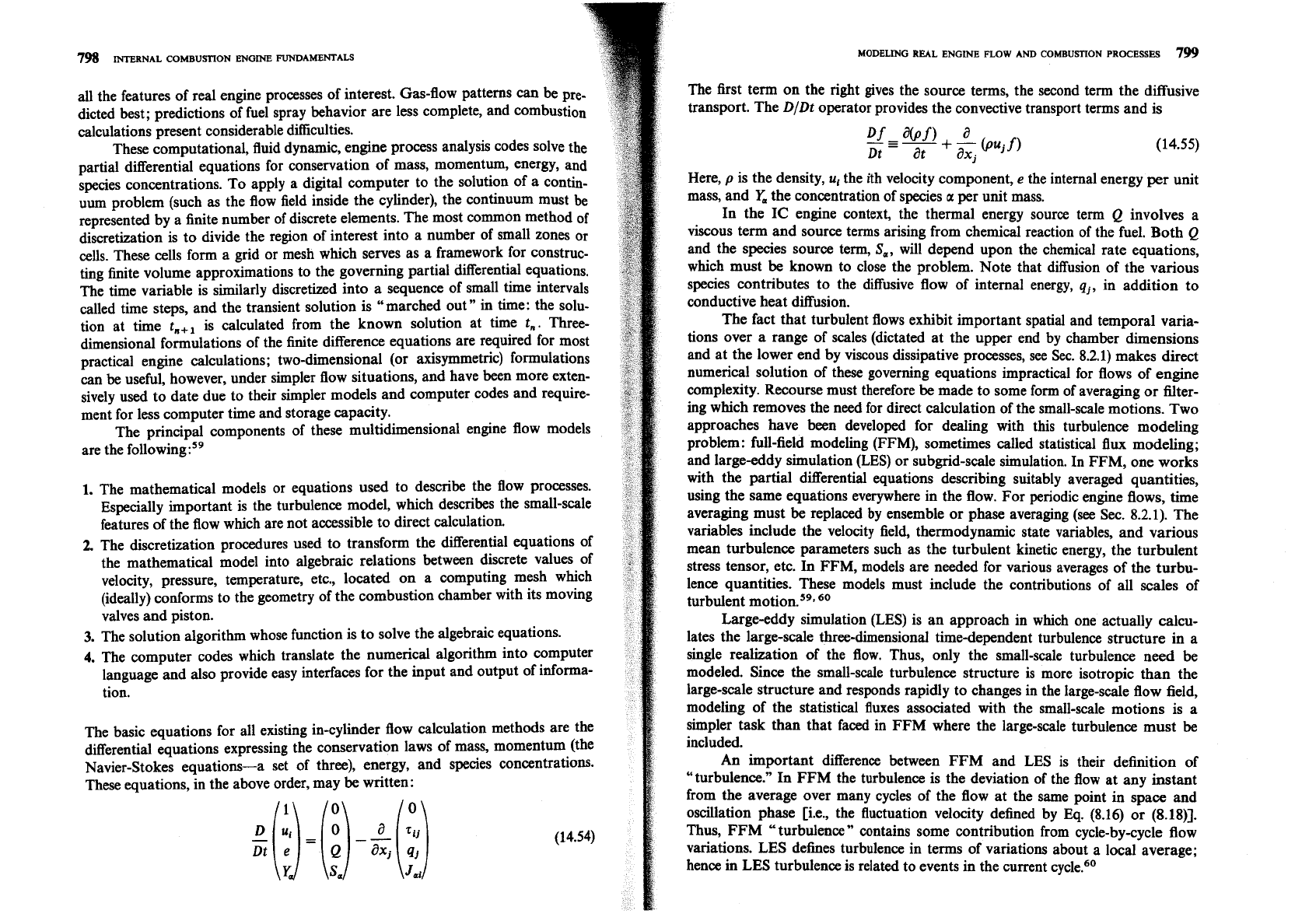
These equations, in the above order, may be written:
i
MODELING REAL ENGINE FLOW AND COMBUSTION PROCESSES
799
The first term on the right gives the source terms, the second term the diffusive
transport. The
D/Dt
operator provides the convective transport terms and is
Here,
p
is the density,
u,
the ith velocity component,
e
the internal energy per unit
mass, and
Y,
the concentration of species
a
per unit mass.
In the IC engine context, the thermal energy source term
Q
involves a
viscous term and source terms arising from chemical reaction of the fuel. Both
Q
and the species source term,
S,,
will depend upon the chemical rate equations,
which must
be
known to close the problem. Note that diffusion of the various
species contributes to the diffusive flow of internal energy,
q,,
in addition to
conductive heat diffusion.
The fact that turbulent flows exhibit important spatial and temporal varia-
tions over a range of scales (dictated at the upper end by chamber dimensions
and at the lower end by viscous dissipative processes, see
Sec. 8.2.1) makes direct
numerical solution of these governing equations impractical for flows of engine
complexity. Recourse must therefore
be
made to some form of averaging or filter-
ing which removes the need for direct calculation of the small-scale motions. Two
approaches have been developed for dealing with this turbulence modeling
problem: full-field modeling (FFM), sometimes called statistical flux modeling;
and large-eddy simulation (LES) or subgrid-scale simulation. In FFM, one works
with the partial differential equations describing suitably averaged quantities,
using the same equations everywhere in the flow. For periodic engine flows, time
averaging must be replaced by ensemble or phase averaging
(see
Sec. 8.2.1). The
variables include the velocity field, thermodynamic state variables, and various
mean turbulence parameters such as the turbulent kinetic energy, the turbulent
stress tensor, etc. In FFM, models are needed for various averages of the turbu-
lence quantities. These models must include the contributions of all scales of
turbulent
motion.s9,
60
Large-eddy simulation (LES) is an approach in which one actually calcu-
lates the large-scale three-dimensional time-dependent turbulence structure in a
single realization of the flow. Thus, only the small-scale turbulence need be
modeled. Since the small-scale turbulence structure is more isotropic than the
large-scale structure and responds rapidly to changes in the large-scale flow field,
modeling of the statistical fluxes associated with the small-scale motions is a
simpler task than that faced in FFM where the
large-scale turbulence must be
included.
An important difference between FFM and LES is their definition of
"turbulence." In FFM the turbulence is the deviation of the flow at any instant
from the average over many cycles of the flow at the same point in space and
oscillation phase
[i.e., the fluctuation velocity defined by Eq. (8.16) or
(8.18)].
Thus, FFM "turbulence" contains some contribution from cycle-by-cycle flow
variations. LES defines turbulence in terms of variations about a local average;
hence in LES turbulence is related to events in the current cycle.60
800
INTERNAL COMBUSTION
ENGINE
FUNDAMENTALS
145.2
Turbulence
Models
In full-jeld modeling (FFM), equations for the averaged variables are formed
from Eqs. (14.54). With periodic engine flows, phase or ensemble averaging must
be
used (see Secs. 8.2.1 and 8.2.2). Since the flow during the engine cycle is corn-
pressed and expanded, mass-weighted averaging (called Favre averaging) can
be
used to make the averaged compressible-flow equations look almost exactly like
the averaged equations for incompressible flows. The combined ensemble-Favre
averaging approach works as follo~s.~'
We denote the phase-averaging process by
{
),
i.e.:
1
{p(x, t))
=
lim
-
C
p(x, t
+
nr)
N-m
n=1
where
z
is the cycle period. We also write {p)
=
P,
and decompose p into
p
=
?,
+
p'. The mass-weighted phase-averaged quantities (indicated by an
overbar) are defined by
N
ax, t)f(x, t)
=
lim
p(x, t
+
nr)
f
(x,
t
+
nz)
(14.57)
N-w
n=l
where all flow variables (except density and pressure) have been decomposed as
f
=
f
+
f.
Note that {p') is zero,
{f)
=x
the mass-weighted phase average off is
zero, but
{
f)
is not zero. With these definitions:
(pf 9)
=
af3
+
m
-
{pfgh)
=
fififi
+fg'h'
+
3-
+
6
f7
+
f
g'h')
(14.58)
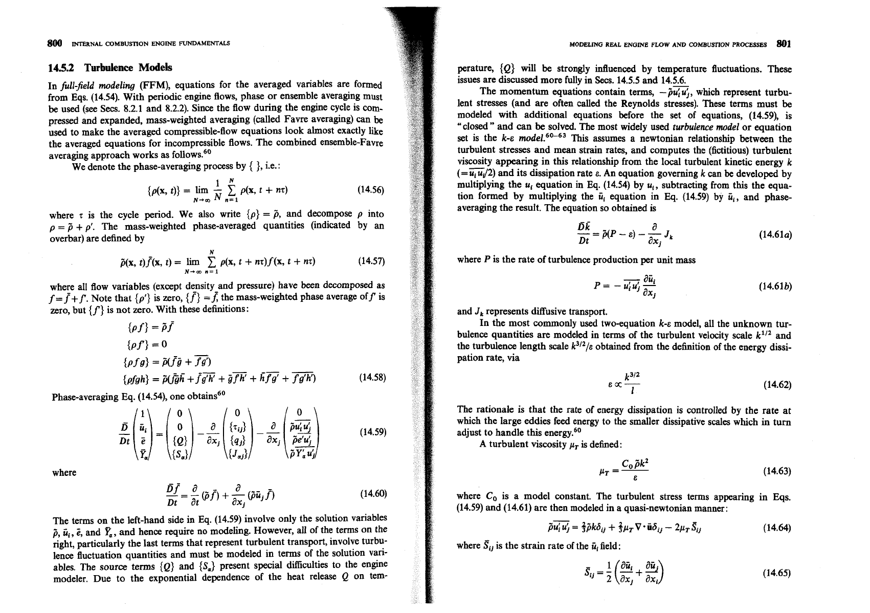
Phase-averaging Eq. (14.54), one obtains6'
where
The terms on the left-hand side in
Eq.
(14.59) involve only the solution variables
3,
ii,,
5,
and
x,
and hence require no modeling. However, all of the terms on the
right, particularly the last terms that represent turbulent transport, involve turbu-
lence fluctuation quantities and must
be
modeled in terms of the solution vari-
ables. The source terms {Q) and
(Sa}
present special difficulties to the engine
modeler. Due to the exponential dependence of the heat release
Q
on tem-
MODELING
REAL
ENGlNE
FLOW
AND COMBUSl7ON
PROCESSES
801
perature, {Q) will be strongly influenced by temperature fluctuations. These
issues are discussed more fully in Secs. 14.5.5 and 14.5.6.
The momentum equations contain terms,
-p&;,
which represent turbu-
lent stresses (and are often called the Reynolds stresses). These terms must
be
modeled with additional equations before the set of equations, (14.59), is
"closed" and can
be
solved. The most widely used turbulence model or equation
set is the k-E rn~del.~"--~~ This assumes a newtonian relationship between the
turbulent stresses and mean strain rates, and computes the (fictitious) turbulent
viscosity appearing in this relationship from the local turbulent kinetic energy k
-
(=
u, uJ2) and its dissipation rate
E.
An equation governing k can
be
developed by
multiplying the u, equation in Eq. (14.54) by u,, subtracting from this the equa-
tion formed by multiplying the
iii
equation in Eq. (14.59) by
ii,,
and phase-
averaging the result. The equation so obtained is
where
P
is the rate of turbulence production per unit mass
-
aii.
p=
-
u!u'
-
a
j
ax,
and
J,
represents diffusive transport.
In the most commonly used two-equation k-E model, all the unknown tur-
bulence quantities are modeled in terms of the turbulent velocity scale k1I2 and
the turbulence length scale
k31Z/&
obtained from the definition of the energy dissi-
pation rate, via
The rationale is that the rate of energy dissipation is controlled by the rate at
which the large eddies feed energy to the smaller dissipative scales which in turn
adjust to handle this energy.'jO
A turbulent viscosity
pT
is defined:
where Co is a model constant. The turbulent stress terms appearing in Eqs.
(14.59) and (14.61) are then modeled in a quasi-newtonian manner:
-
pu; u;
=
$kdij
+
spT
V
iidij
-
2~,
5,
(14.64)
where
Si,
is the strain rate of the
iii
field:
802
INTERNAL COMBUSTION ENGINE FUNDAMENTALS
The viscous-stress terms in the momentum equations are evaluated using a new-
tonian constitutive relation. The turbulent-diffusion terms in the various trans-
port equations are modeled using the turbulent diffusivity. The diffusing flux of a
quantity
4
is given by
where
a+
is a turbulent Prandtl number for
4.
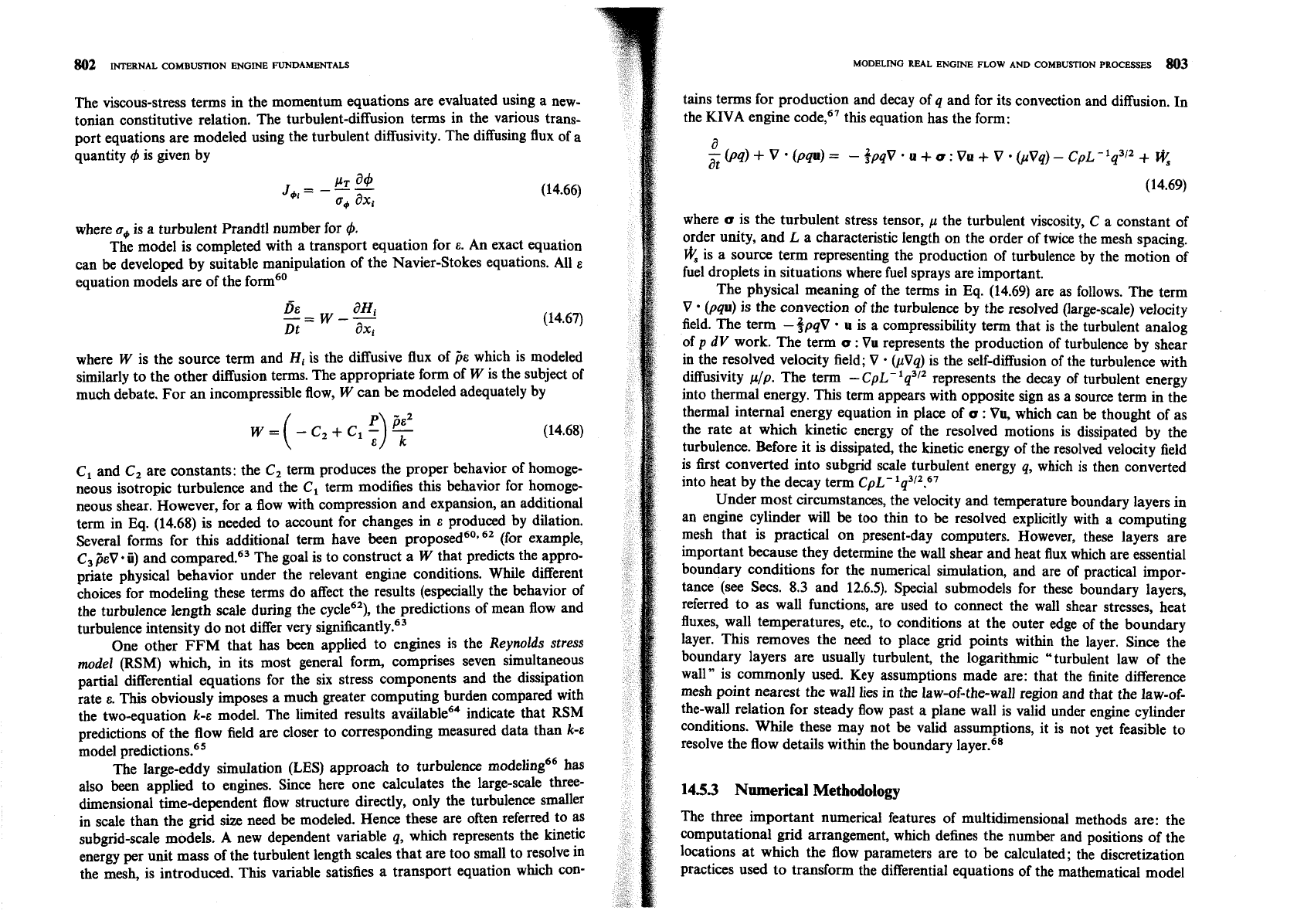
The model is completed with a transport equation for
E.
An exact equation
can be developed by suitable manipulation of the Navier-Stokes equations. All
E
equation models are of the form6'
where
W
is the source term and
Hi
is the diffusive flux of
,%
which is modeled
similarly to the other diffusion terms. The appropriate form of
W
is the subject of
much debate. For an incompressible flow,
W
can be modeled adequately by
C, and C, are constants: the C, term produces the proper behavior of homoge-
neous isotropic turbulence and the C, term modifies this behavior for homoge-
neous shear. However, for a flow with compression and expansion, an additional
term in Eq. (14.68) is needed to account for changes in
E
produced by dilation.
Several forms for this additional term have been propo~ed~'.~~ (for example,
C,
~EV
ii)
and compared.63 The goal is to construct a
W
that predicts the appro-
priate physical behavior under the relevant engine conditions. While different
choices for modeling these terms do affect the results (especially the behavior of
the turbulence length scale during the cycle6'), the predictions of mean flow and
turbulence intensity do not differ very
~ignificantly.~~
One other
FFM
that has been applied to engines is the
Reynolds stress
model
(RSM) which, in its most general form, comprises seven simultaneous
partial differential equations for the six stress components and the dissipation
rate
E.
This obviously imposes a much greater computing burden compared with
the two-equation k-E model. The limited results a~riilable~~ indicate that RSM
predictions of the flow field are closer to corresponding measured data than
k-E
model
prediction^.^^
The large-eddy simulation (LES) approach to turbulence modeling66 has
also been applied to engines. Since here one calculates the large-scale three-
dimensional time-dependent flow structure directly, only the turbulence smaller
in scale than the grid size need be modeled. Hence these are often referred to as
subgrid-scale models.
A
new dependent variable q, which represents the kinetic
energy per unit mass of the turbulent length scales that are too small to resolve in
the mesh, is introduced. This variable satisfies a transport equation which con-
tains terms for production and decay of q and for its convection and diffusion. In
the KIVA engine code,67 this equation has the form:
where
o
is the turbulent stress tensor, p the turbulent viscosity, C a constant of
order unity, and
L
a characteristic length on the order of twice the mesh spacing.
@
is a source term representing the production of turbulence by the motion of
fuel droplets in situations where fuel sprays are important.
The physical meaning of the terms in Eq. (14.69) are as follows. The term
V
(pqu)
is the convection of the turbulence by the resolved (large-scale) velocity
field. The term -3~qV
u
is a compressibility term that is the turbulent analog
of
p
dV
work. The term
o
:
Vu represents the production of turbulence by shear
in the resolved velocity field;
V
.
(pVq) is the selfdiffusion of the turbulence with
diffusivity
pip.
The term -CpL-'q3l2 represents the decay of turbulent energy
into thermal energy. This term appears with opposite sign as a source term in the
thermal internal energy equation in place of
o
:
Vu, which can be thought of as
the rate at which kinetic energy of the resolved motions is dissipated by the
turbulence. Before it is dissipated, the kinetic energy of the resolved velocity field
is first converted into subgrid scale turbulent energy
q,
which is then converted
into heat by the decay term CpL-1q3/2.67
Under most circumstances, the velocity and temperature boundary layers in
an engine cylinder will be too thin to be resolved explicitly with a computing
mesh that is practical on present-day computers. However, these layers are
important because they determine the wall shear and heat flux which are essential
boundary conditions for the numerical simulation, and are of practical
irnpor-
tance (see Secs.
8.3
and 12.6.5). Special submodels for these boundary layers,
referred to as wall functions, are used to connect the wall shear stresses, heat
fluxes, wall temperatures, etc., to conditions at the outer edge of the boundary
layer. This removes the need to place grid points within the layer. Since the
boundary layers are usually turbulent, the logarithmic "turbulent law of the
wall" is commonly used. Key assumptions made are: that the finite difference
mesh point nearest the wall lies in the law-of-the-wall region and that the law-of-
the-wall relation for steady flow past a plane wall is valid under engine cylinder
conditions. While these may not be valid assumptions, it is not yet feasible to
resolve the flow details within the boundary
layer.68
1453
Numerical Methodology
The three important numerical features of multidimensional methods are: the
computational grid arrangement, which defines the number and positions of the
locations at which the flow parameters are to be calculated; the discretization
practices used to transform the differential equations of the mathematical model
*.
into algebraic equations; and the solution algorithms employed to obtain the
flow parameters from the discrete equations.59*
65
COMPUTING
MESH.
The requirements of the computing mesh are:
1.
It adequately fits the topography of the combustion chamber and/or inlet
port, including the moving components.
2.
It allows control of local resolution to obtain the maximum accuracy with a
given number of grid points.
3.
It has the property that each interior grid point is connected to the same
number of neighboring points.
The first requirement obviously follows from the need to simulate the effects of
changes in engine geometry. The second'requirement stems from the fact
that
computing time increases at least linearly with the number of mesh points. Thus
it is desirable that the mesh allow concentration of grid points in regions where
steep gradients exist such as jets and boundary layers. The third requirement
comes from the need for the mesh to be topologically rectangular in some trans-
formed space so that highly efficient equation solvers for such mesh systems can
be utilized.
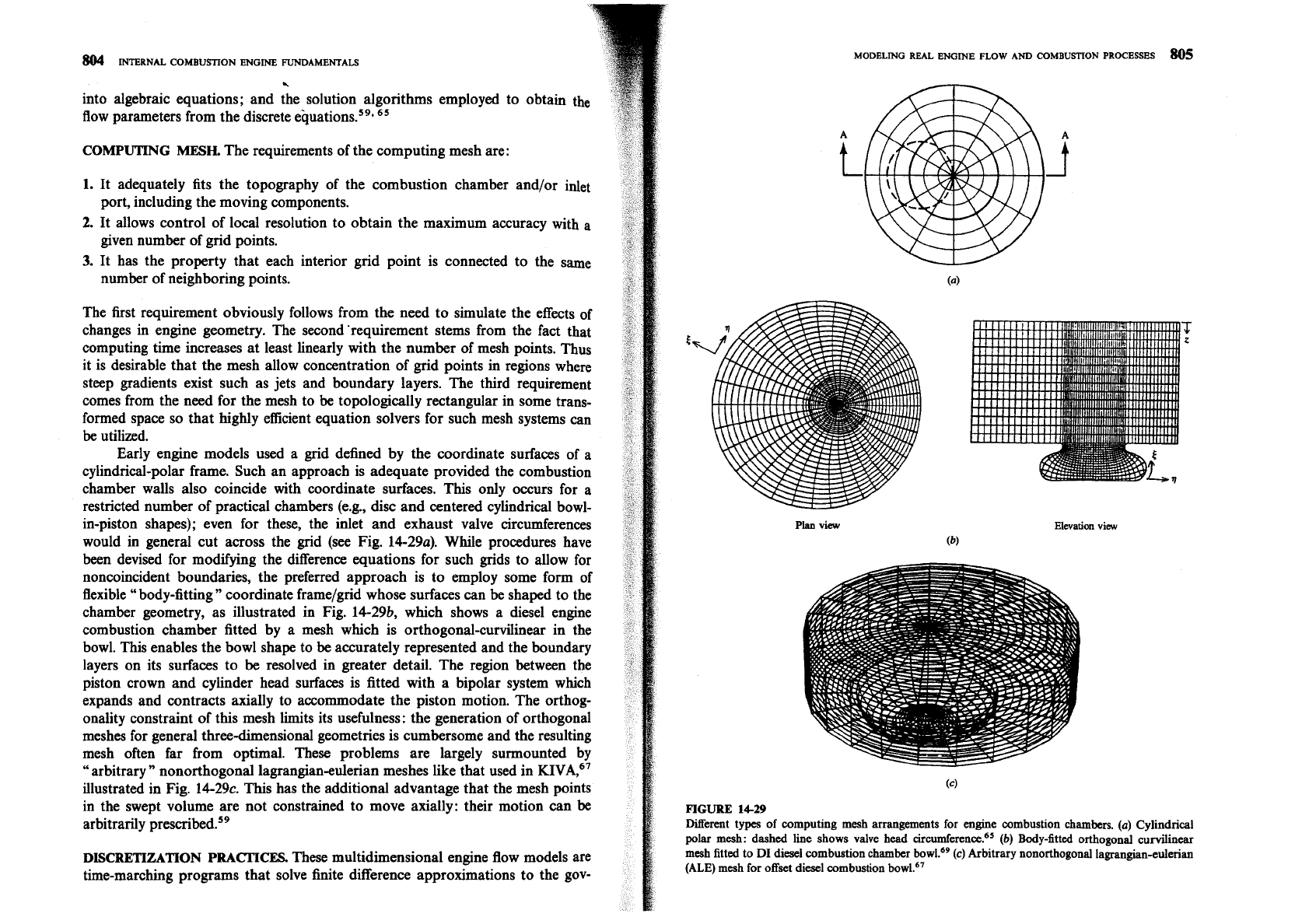
Early engine models used a grid defined by the coordinate surfaces of
a
cylindrical-polar frame. Such an approach is adequate provided the combustion
chamber walls also coincide with coordinate surfaces. This only occurs for a
restricted number of practical chambers
(e.g.,
disc
and centered cylindrical bowl-
in-piston shapes); even for these, the inlet and exhaust valve circumferences
would in general cut across the grid (see Fig. 14-29a). While procedures have
been devised for modifying the difference equations for such grids to allow for
noncoincident boundaries, the preferred approach is to employ some form of
flexible
"
body-fitting" coordinate frame/grid whose surfaces can be shaped to the
chamber geometry, as illustrated in Fig. 14-29b, which shows a diesel engine
combustion chamber fitted by a mesh which is orthogonal-curvilinear in the
bowl. This enables the bowl shape to be accurately represented and the boundary
layers on its surfaces to be resolved in greater detail. The region between the
piston crown and cylinder head surfaces is fitted with a bipolar system which
expands and contracts axially to accommodate the piston motion. The orthog-
onality constraint of this mesh limits its usefulness: the generation of orthogonal
meshes for general three-dimensional geometries is cumbersome and the resulting
mesh often far from optimal. These problems are largely surmounted by
"
arbitrary
"
nonorthogonal lagrangianeulerian meshes like that used in KIVA,~'
illustrated in Fig. 14-29c. This has the additional advantage that the mesh points
in the swept volume are not constrained to move axially: their motion can
be
arbitrarily pre~cribed.~'
DISCRETIZATION PRACIICES.
These multidimensional engine flow models are
time-marching programs that solve finite difference approximations to the gov-
Plan view
Elwation
view
(b)
FIGURE
1429
Different types of computing mesh arrangements for engine combustion chambers.
(a)
Cylindrical
polar mesh: dashed line shows valve head ~ircumference.~'
(b)
Bodyatted orthogonal curvilinear
mesh fitted to
DI
diesel combustion chamber bowL6'
(c)
Arbitrary nonorthogonal lagrangian-eulerian
(ALE)
mesh for offset diesel combustion bowL6'
INTERNAL
COMBUSTION ENGINE
FUNDAMENTALS
erning differential equations. The individual cells formed by the mesh or grid
serve as the spatial framework for constructing these algebraic finite difference
equations. The time variable is similarly discretized into a sequence of small time
intervals called time steps: the solution at time t,,, is calculated from the known
solution at time t,. The spatial differencing is made conservative wherever
pas-
sible. The procedure used is to difference the basic equations in integral form,
with the volume of a typical cell used as the control volume and the divergence
terms transformed into surface integrals using the divergence theorem.67
The discretized equations for any dependent variable
4
are of the general
form
:
AP4r1
=
x
A,&,+'
+
s+,,
V,
+
A:I#:
(14.70)
n
where the A's are coefficients expressing the combined influences of convection
and diffusion,
S+,
,
V,
is the source integral over the cell volume
Vp
,
the subscript
p
denotes a typical node point in the mesh, the summation is over its (six)
nearest neighbors, and the superscripts i
+
1 and
i
denote
"
new" and "old"
values, at times t
+
6t and t, respectively, where 6t is the size of the time step.69
Until recently all methods involved similar spatial approximations to calcu-
late convective and diffusive transport, using a blend of first-order upwind differ-
encing for the former and second-order central differencing for the latter.
Unfortunately, all discretization practices introduce inaccuracies of some kind,
and the standard first-order upwind scheme produces spatial diffusion errors
which act in the same way as real diffusion to "smooth" the solutions. The
magnitude of the numerical diffusion reduces as the mesh density is increased,
but even with as many
as
50 mesh points in each coordinate direction, the effect
is not eliminated.
A
recent development has been the introduction of "higher
order" spatial approximations which, in the past, had a tendency to produce
spurious extrema. This problem has been overcome by the use of
"
flux blending"
techniques. First-order upwind and higher-order approximations are blended in
appropriate proportions to eliminate the overshoots of the latter. Even with these
schemes, however, true mesh-independent solutions could not be achieved with
densities of up to
50 nodes in each coordinate direction; so there is still a need for
further impr~vernent.~~
SOLUTION
ALGORITHMS.
Numerical calculations of compressible flows are
inefficient at low Mach numbers because of the wide disparity between the time
scales associated with convection and with the propagation of sound waves.
While all methods use first-order temporal discretization and are therefore of
comparable accuracy, they differ in whether forward or backward differencing is
employed in the transport equations leading to implicit or explicit discrete equa-
tions, respectively. In explicit schemes, this inefficiency occurs because the time
steps needed to satisfy the sound-speed stability condition are much smaller than
those needed to satisfy the convective stability condition alone. In implicit
schemes, the inefficiency manifests itself in the additional computational labor
needed to solve the implicit (simultaneous) system of equations at each time step.
This solution is usually performed by iterative techniques.
The computing time requirements of these two approaches scale with the
number of equations n and the number of mesh points m, as follows. For explicit
methods, computing time scales as nm, but the time step is limited by the stability
condition as summarized above. For implicit methods, computing time scales as
n3m and At is only limited by accuracy considerations.
One procedure used, a
semi-implicit method, is the acoustic subcycling
method. All terms in the governing equations that are not associated with sound
waves are explicitly advanced with a larger time step At similar to that used with
implicit methods. The terms associated with acoustic waves (the compression
terms in the continuity and energy equations and the pressure gradient in the
momentum equation) are explicitly advanced using a smaller time step
St that
satisfies the sound-speed stability criterion
pq. (14.23)], and of which the
main
time step is an integral multiple. While this method works well in many IC
engine applications where the Mach number is not unduly low, it is unsuitable
for very low Mach number flows since the number of subcycles
(At/&) tends to
infinity
as
the Mach number tends to zero. For values of At/& greater than 50 an
implicit scheme becomes more efficient. Pressure gradient scaling can be used to
extend the method to lower Mach numbers. The Mach number is artificially
increased to a larger value (but still small in an absolute sense) by multiplying the
pressure gradient in the momentum equation by a time-dependent scaling factor
l/a(t)2, where a(t)
>
1. This reduces the effective sound speed by the factor a. This
does not significantly affect the accuracy of the solution because the pressure
gradient in low Mach number flows is effectively determined by the flow field and
not vice versa. Coupling pressure gradient scaling with acoustic subcycling
reduces the number of subcycles by
a.67
The implicit equations that result from forward differencing consist of
simultaneous sets for all variables and thus require more elaborate methods of
solution. However, they contain no intrinsic stability constraints. Fully iterative
solution algorithms for solution of these equation sets are being replaced with
more
efficient simultaneous linear equation solvers.65
145.4
Flow Field Predictions
To illustrate the potential for multidimensional modeling of IC engine flows,
examples of the output from such calculations will now be reviewed.
A
large
amount of information on many fluid flow and state variables is generated with
each calculation, and the processing, organization, and presentation of this infor-
mation are tasks of comparable scope to its generation! Flow field results are
usually presented in terms of the gas velocity vectors at each grid point of the
mesh in appropriately selected planes. Arrows are usually used to indicate the
direction and magnitude (by length) of each vector. Examples of such plots--of
the flow pattern in the cylinder during the intake process-are shown in Fig.
14-
30.70 The flow field is shown
60"
ATC during the intake stroke. A helical intake
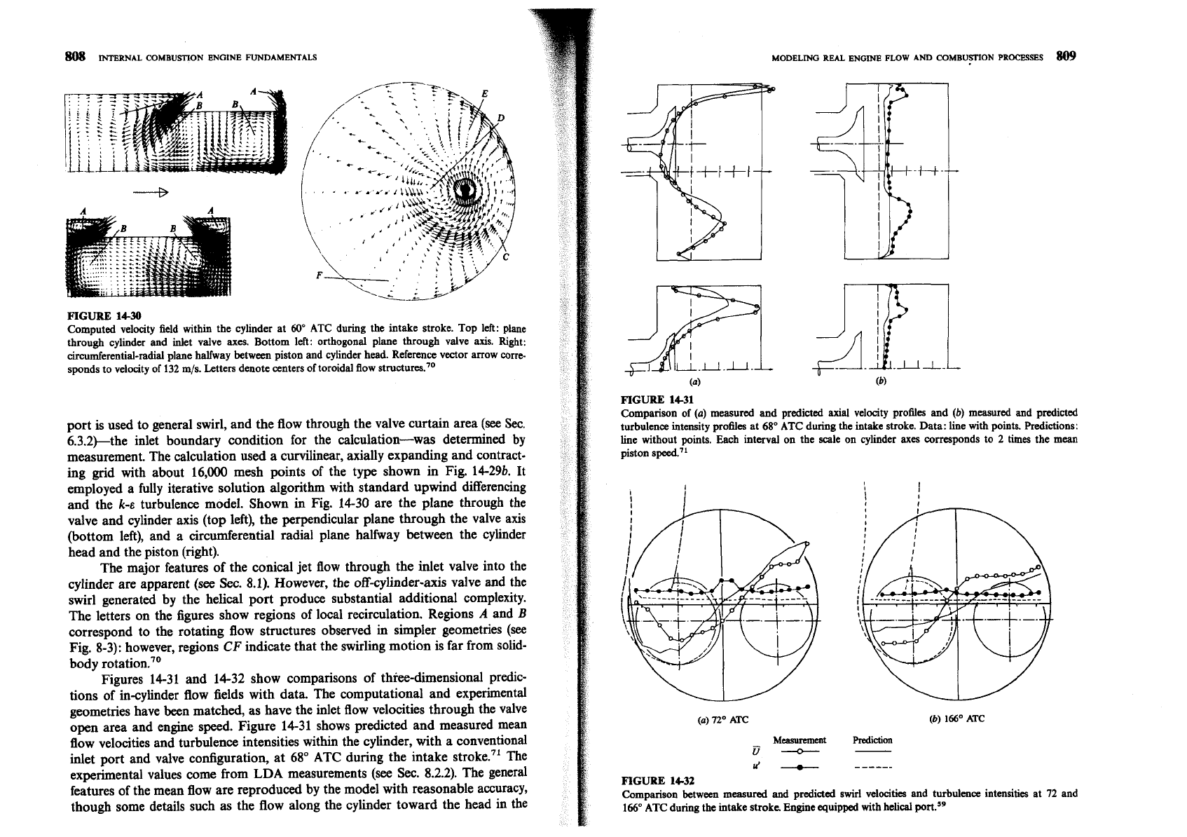
FIGURE 14-30
Computed velocity field within the cylinder at
60"
ATC during the intake stroke. Top left: plane
through cylinder and inlet valve
axes.
Bottom left: orthogonal plane through valve axis. Right:
circumferential-radial plane halfway between piston and cylinder head. Reference vector arrow corre-
sponds to velocity of
132 m/s. Letters denote centers of toroidal flow structures.70
port is used to general swirl, and the flow through the valve curtain area (see
Sec.
6.3.2)-the inlet boundary condition for the calculation-was determined by
measurement. The calculation used a curvilinear, axially expanding and contract-
ing grid with about 16,000 mesh points of the type shown in Fig.
14-296. It
employed a fully iterative solution algorithm with standard upwind differencing
and the
k-E
turbulence model. Shown
in
Fig. 14-30 are the plane through the
valve and cylinder axis (top left), the perpendicular plane through the valve axis
(bottom left), and a circumferential radial plane halfway between the cylinder
head and the piston (right).
The major features of the conical jet flow through the inlet valve into the
cylinder are apparent (see
Sec. 8.1). However, the off-cylinder-axis valve and the
swirl generated by the helical port produce substantial additional complexity.
The letters on the figures show regions of local recirculation. Regions
A
and
B
correspond to the rotating flow structures observed
in
simpler geometries (see
Fig. 8-3): however, regions
CF
indicate that the swirling motion is far from solid-
body r~tation.~'
Figures 14-31 and 14-32 show comparisons of thiee-dimensional predic-
tions of in-cylinder flow fields with data. The computational and experimental
geometries have been matched, as have the inlet flow velocities through the valve
open area and engine speed. Figure 14-31 shows predicted and measured mean
flow velocities and turbulence intensities within the cylinder, with a conventional
inlet port and valve configuration, at 68' ATC during the intake stroke.71 The
experimental values come from LDA measurements (see
Sec. 8.2.2). The general
features of the mean flow are reproduced by the model with reasonable accuracy,
though some details such as the flow along the cylinder toward the head in the
MODELING
REAL
ENGINE
FLOW
AND
COMBUFN
PROCBSSES
809
FIGURE 1431
Comparison of
(a)
measured and predicted axial velocity profiles and
(b)
measured and predicted
turbulence intensity pro6les at
68O
ATC during the intake stroke. Data: line with points. Predictions:
line without points. Each interval on the scale on cylinder axes corresponds to
2
times the mean
piston speed."
(a)
72'
ATC
(b)
166'
ATC
Measurement
Prediction
u
-
u'
-
------
FIGURE 14-32
Comparison between measured and predicted swirl velocities and turbulence intensities at
72
and
166"
ATC
during the intake stroke. Engine equipped with helical
ports9
