Heywood J.B. Internal Combustion Engines Fundamentals
Подождите немного. Документ загружается.

750
INTERNAL
COMBUSTION
ENGINE
FUNDAMENTALS
understanding of critical phenomena. Hence, since models will continue
t
develop greater completeness and generality, the emphasis in this chapter is on
the basic relationships used in engine process models rather than the current
status of these models.
Finally, an important issue in any overall engine model is balance in corn.
plexity and detail amongst the process submodels.
A
model is no more accurate
than its weakest link. Thus critical phenomena should
be
described at cornpara.
ble levels of sophistication.
14.2 GOVERNING EQUATIONS FOR
OPEN THERMODYNAMIC SYSTEM
It is often required to model a region of the engine as an open thermodynamic
system. Examples are the cylinder volume and the intake and exhaust manifolds
(or portions of these volumes). Such a model is appropriate when the gas inside
the open system boundary can
be
assumed uniform in composition and state at
each point in time, and when that state and composition vary with time due to
heat transfer, work transfer and mass flow across the boundary, and boundary
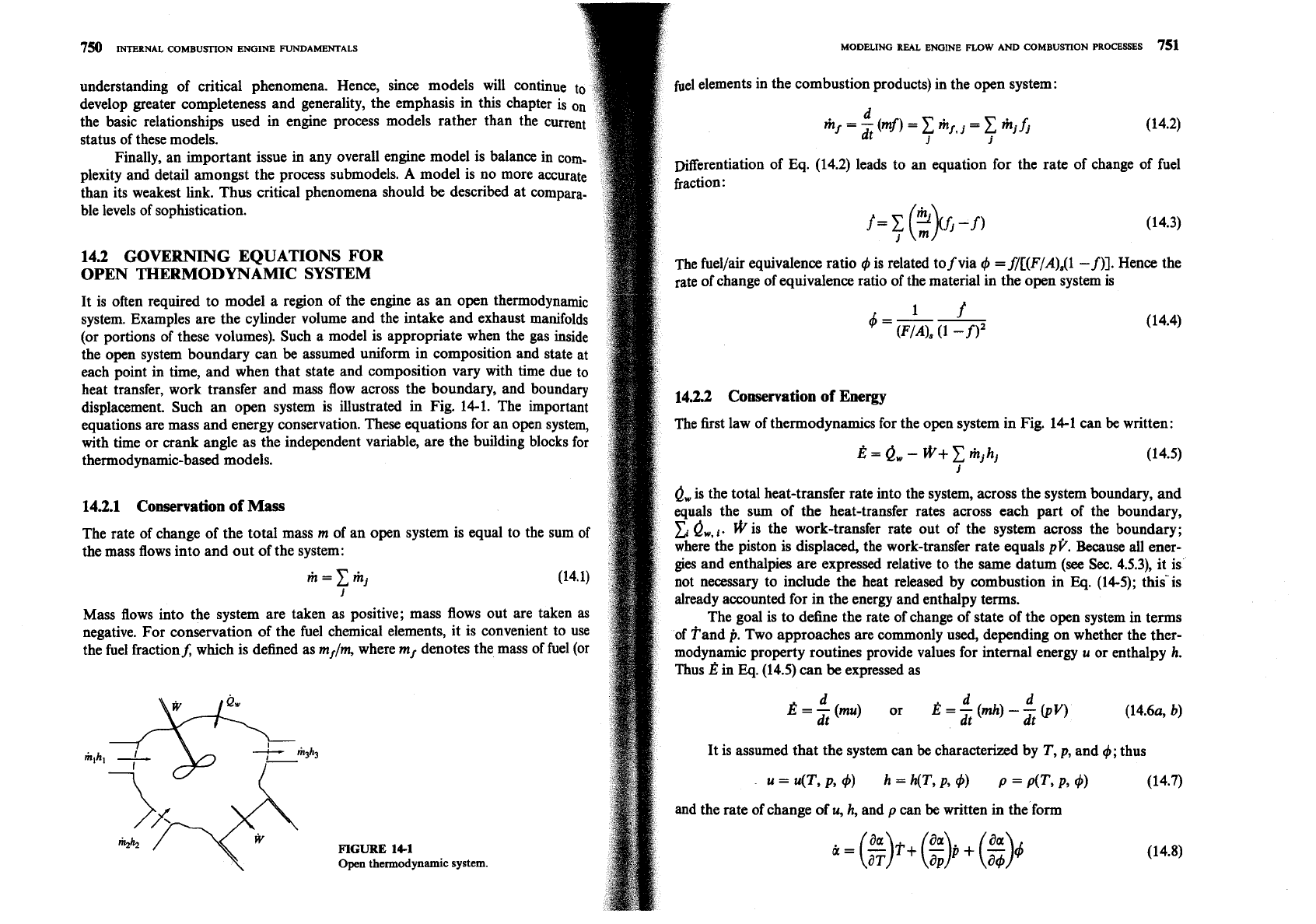
displacement. Such an open system is illustrated in Fig. 14-1. The important
equations are mass and energy conservation. These equations for an open system,
with time or
crank
angle as the independent variable, are the building blocks for
thermodynamic-based models.
14.2.1 Conservation of
Mass
The rate of change of the total mass m of an open system is equal to the sum of
the mass flows into and out of the system:
m=c$
i
Mass flows into the system are taken as positive; mass flows out are taken
as
negative. For conservation of the fuel chemical elements, it is convenient to use
the fuel fractionf, which is defined as m,/m, where m, denotes the mass of fuel (or
FIGURE
14-1
Open
thermodynamic
system.
MODELING REAL ENGINE FLOW AND COMBUSTION PROCESSES
751
fuel elements in the combustion products) in the open system:
Differentiation of Eq. (14.2) leads to an equation for the rate of change of fuel
fraction
:
The fuellair equivalence ratio is related to
f
via
4
=fI[(F/A)dl
-
f)]. Hence the
rate of change of equivalence ratio of the material in the open system is
142.2 Conservation of Energy
The first law of thermodynamics for the open system in Fig. 14-1 can
be
written:
ow
is the total heat-transfer rate into the system, across the system boundary, and
equals the sum of the heat-transfer rates across each part of the boundary,
ow,,.
@is the work-transfer rate out of the system across the boundary;
where the piston is displaced, the work-transfer rate equals
pt.
Because all ener-
gies and enthalpies are expressed relative to the same datum
(see
Sec.
4.5.3), it is
not necessary to include the heat released by combustion in
Eq.
(14-5); thisis
already accounted for in the energy and enthalpy terms.
The goal
is
to define the rate of change of state of the open system
in
terms
of fand
p.
Two approaches are commonly used, depending on whether the ther-
modynamic property routines provide values for internal energy
u
or enthalpy
h.
Thus
E
in
Eq.
(14.5) can
be
expressed as
It is assumed that the system can
be
characterized by
T,
p,
and
4;
thus
and the rate
of
change of
u,
h, and
p
can
be
written in the form
752
INTERNAL
COMBUSTION
ENGINE
FUNDAMENTALS MODELING
REAL
ENGINE
FLOW
AND
COMBUSTION PROCESSES
753
where
a
is
u,
h,
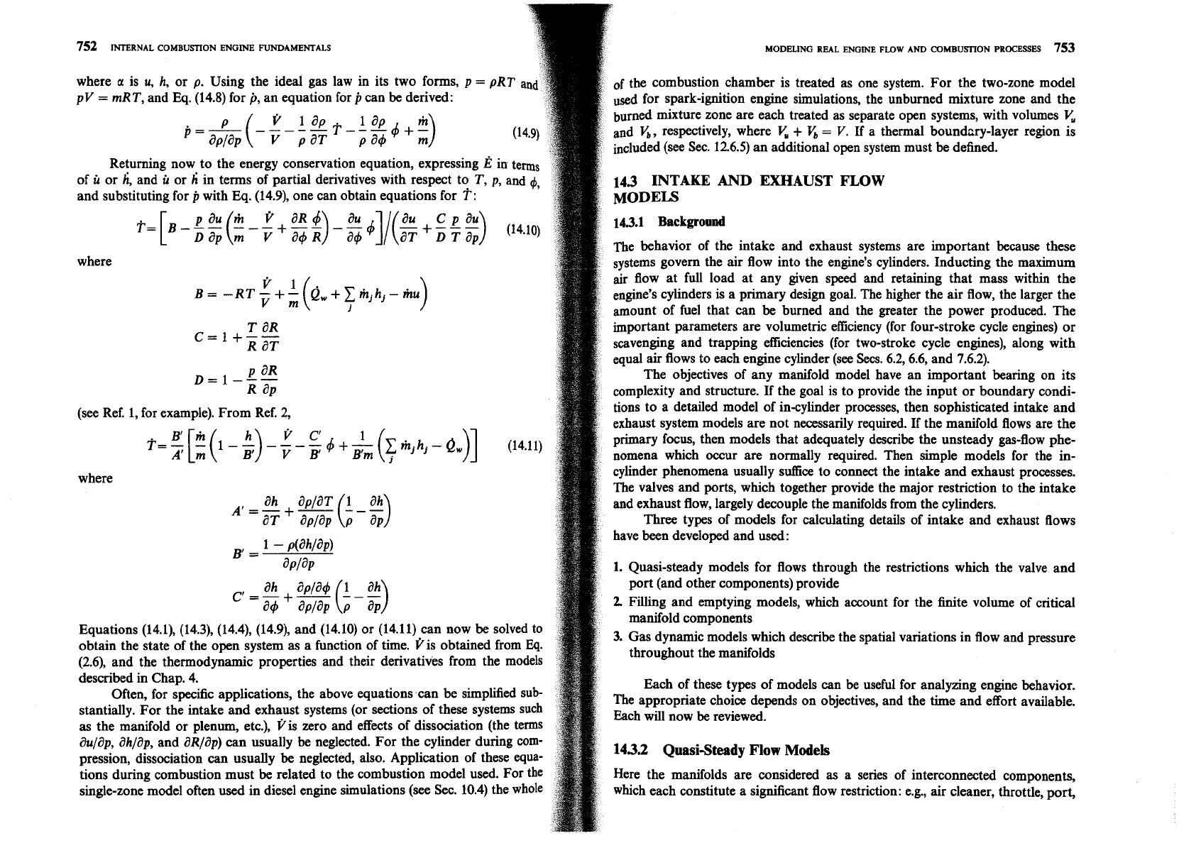
or p. Using the ideal gas law in its two forms, p
=
pRT an
of
the combustion chamber is treated as one system. For the two-zone model
pV
=
mRT, and Eq. (14.8) for
p,
an equation for
p
can be derived:
used for spark-ignition engine simulations, the unburned mixture zone and the
burned mixture zone are each treated as separate open systems, with volumes
and
V,,
respectively, where
+
V,
=
V.
If a thermal boundnry-layer region is
included (see Sec. 12.6.5) an additional open system must be defined.
Returning now to the energy conservation equation, expressing
E
in
terms
of
u
or
h,
and
u
or
h
in terms of partial derivatives with respect to
T,
p, and
4,
14.3
INTAKE
AND
EXHAUST
FLOW
and substituting for
p
with Eq. (14.9), one can obtain equations for
T:
143.1
Background
The behavior of the intake and exhaust systems are important because these
where
systems govern the air flow into the engine's cylinders. Inducting the maximum
air flow at full load at any given speed and retaining that mass within the
engine's cylinders is a primary design goal. The higher the air flow, the larger the
amount of fuel that can be burned and the greater the power produced. The
T
aR
important parameters are volumetric efficiency (for four-stroke cycle engines) or
C=l+--
R aT
scavenging and trapping efficiencies (for two-stroke cycle engines), along with
equal air flows to each engine cylinder (see Secs. 6.2, 6.6, and 7.6.2).
P aR
D=I---
The objectives of any manifold model have an important bearing on its
R
a~
complexity and structure.
If
the goal is to provide the input or boundary condi-
(see Ref. 1, for example). From Ref. 2,
tions to a detailed model of in-cylinder processes, then sophisticated intake and
exhaust system models are not necessarily required. If the manifold flows are the
primary focus, then models that adequately describe the unsteady gas-flow phe-
nomena which occur are normally required. Then simple models for the in-
where
cylinder phenomena usually suffice to connect the intake and exhaust processes.
The valves and ports, which together provide the major restriction to the intake
and exhaust flow, largely decouple the manifolds from the cylinders.
Three types of models for calculating details of intake and exhaust flows
have been developed and used:
B'=
1
-
ahla la^)
~PI~P
1.
Quasi-steady models for flows through the restrictions which the valve and
port (and other components) provide
2.
Filling and emptying models, which account for the finite volume of critical
manifold components
Equations
(14.1), (14.3), (14.4), (14.9), and (14.10) or (14.11) can now be solved to
3.
Gas dynamic models which describe the spatial variations in flow and pressure
obtain the state of the open system as a function of time. tis obtained from
Eq.
throughout the manifolds
(2.6), and the thermodynamic properties and their derivatives from the models
described in Chap. 4.
Each of these types of models can be useful for analyzing engine behavior.
Often, for specific applications, the above equations can be simplified
sub-
The appropriate choice depends on objectives, and the time and effort available.
stantially. For the intake and exhaust systems (or sections of these systems such
Each will now be reviewed.
as the manifold or plenum, etc.), 3is zero and effects of dissociation (the terms
aulap, ahlap, and aR/ap)
can
usually
be
neglected. For the cylinder during
com-
pression, dissociation can usually be neglected, also. Application of these equa-
143.2
QuasiSteady
Flow
Models
tions during combustion must be related to the combustion model used. For the
Here the manifolds are considered
as
a series of interconnected components,
single-zone model often used in diesel engine simulations (see Sec. 10.4) the whole
which each constitute a significant flow restriction: e.g., air cleaner, throttle, port,
754
INTERNAL COMBUSTION ENGINE FUNDAMENTALS
and valve for the intake system. The flow restriction each of these conpone
represents is defined by their geometry and discharge coefficient, usually de
mined empirically under steady-state conditions. The gas flow rate throu
component is computed using steady one-dimensional flow equations
[
C, Eqs. (C.8) and (C.911: the actual flow is assumed to be quasi stead
components are connected by the gas flow passing through them and the
pres-
sure ratios across them; mass accumulation between components is neglected.
Quasi-steady models are often used to calculate the flow into and out of the
cylinder through the inlet and exhaust valves (see Sees. 6.3 and 6.5 and Fig. 6-20).
If the pressure variation with time upstream of the valve is known or is small,
as
usually occurs with large plenums and short manifold pipe lengths, such metho&
are accurate enough to be useful. This approach has been used extensively with
engine cycle simulations which predict e&ne performance characteristics from a
thermodynamics-based analysis, to calculate the mass flow rates into and out of
the cylinder (see Sec. 14.4). Such methods are not able to predict the variation of
volumetric efficiency with engine speed, however, because many of the
phe-
nomena which govern this variation are omitted from this modelling approach
(see Sec. 6.2 and Fig. 6-9).
1433
Filling
and
Emptying
Methods
In "filling and emptying" models, the manifolds (or sections of manifolds) are
represented by finite volumes where the mass of gas can increase or decrease with
time. Such models can range from treating the whole intake or exhaust system as
a single volume to dividing these systems into many sections, with flow
restrictions such as the air cleaner, throttle valve, or inlet valve at the beginning,
in between volumes, or at the end. Each volume is then treated as a control
volume (an open system of fixed volume) which contains gas at a uniform state.
The mass and energy conservation equations developed in
Sec. 14.2 [Eqs. (14.1),
(14.3), (14.9), and (14.10) or (14.11)], coupled with information on the mass flow
rates into and out of each volume [e.g., determined by the equations for flow
through a restriction, Eqs.
(C.8)
and (C.911 are used to define the gas state in each
control volume. For intake and exhaust flows these equations can be simplified
since the volumes are fixed
(V
=
O),
gas composition can be assumed frozen
(aulap, ahlap, and aR/ap are then zero), unless backflow occurs or recycled
exhaust is used for emission control changes in fuel fraction are not significant,
and for intake systems it may be acceptable to omit heat transfer to the walls
(0,). Such methods characterize the contents of the manifold (or a region thereof)
with a single gas temperature, pressure, and composition. These vary periodically
with time as each cylinder in turn draws on the intake system and discharges to
the exhaust system. Also, under transient conditions when engine load and/or
speed change with time, manifold conditions will vary until the new engine
steady-state conditions are established. Watson and ~anota~ discuss the applica-
tion of filling and emptying models to manifolds in more detail. Such models can
characterize these time-varying phenomena, spatially averaged over each
mani-
MODELING REAL ENGINE FLOW AND COMBUSTION PROCESSES
755
C
I
I1
1
I
Experiment
1
-
(compact
emptying model,
with
experimen-
90
180
270
360
tal data. Singlecylinder two-
Experiment
stroke loopscavenged direct-
(compact injection diesel engine. Different
manifold)
ratios of exhaust svstem volume
V,
to displaced volume
V,,
and
exhaust manifold
shape^.^
1.0
EPO Exhaust port opens
IPO
Inlet port opens
IPC Inlet port closes
Crank
angle,
deg
EPC Exhaust port closes
fold region corresponding to each volume analyzed: however, they cannot
describe the spatial variation of pressure (and other gas properties) due to
unsteady gas dynamics in the manifolds.
A
simple application of a filling and emptying model to the intake manifold
of a spark-ignition engine was described in Sec. 7.6.2. The manifold was analyzed
as a single control volume with the throttle plate controlling mass flow into the
manifold and the engine cylinders controlling mass flow out. An equation for the
rate of change of manifold pressure
[Eq. (7.2211 was derived and used to explain
how the air flow past the throttle varied as the throttle open angle was increased,
as would occur at the start of a vehicle acceleration at part-throttle conditions
(see Fig. 7-24).
A second example will illustrate the conditions under which filling and
emptying models give sufficiently accurate predictions to
be
u~eful.~ It concerns a
single-cylinder two-stroke cycle loopscavenged direct-injection diesel engine. The
engine was modeled as three open systems (the intake system, the cylinder, the
exhaust system) connected by flow restrictions. Various exhaust manifold
volumes and shapes were examined, using nozzles at the manifold exit to simu-
late the exhaust-driven turbine. The in-cylinder models were calibrated to match
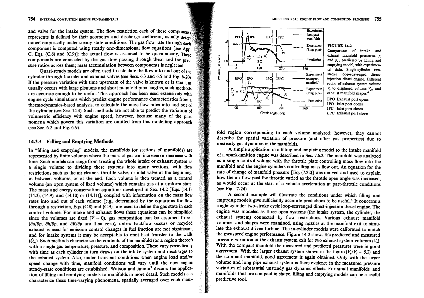
the measured engine performance. Figure 14-2 shows the predicted and measured
pressure variation at the exhaust system exit for two exhaust system volumes
(K).
With the compact manifold the measured and predicted pressures were in good
agreement. With the larger exhaust system shown in the figure
(VJb
=
5.2)
and
the compact manifold, good agreement is again obtained. Only with the larger
volume and long pipe exhaust system is there evidence in the measured pressure
variation of substantial unsteady gas dynamic effects. For small manifolds, and
manifolds that are compact in shape, filling and emptying models can be a useful
predictive tool.
756
INTERNAL
COMBU~ON
ENGINE
FUNDAMENTALS
143.4
Gas
Dynamic
Models
Many induction and exhaust system design variables determine overall per.
formance. These variables include the length and cross-sectional area of both
primary and secondary runners, the volume and location of the plenums or junc-
tions which join the various runners, the entrance or exit angles of the runners at
a junction, the number of engine cylinders and their dimensions, intake and
exhaust port and valve design, and valve lift and timing (see Secs. 6.2,6.3,6.7, and
7.6). Most of this geometric detail is beyond the level which can be incorporated
into the models discussed above. Coupled with the pulsating nature of the flow
into and out of each cylinder, these details create significant gas dynamic effects
on intake and exhaust flows which require a more complete modeling approach.
Gas
dynamic models have been
in
use for a number of years to study
engine gas exchange processes. These models
use
the mass, momentum, and
energy conservation equations for the unsteady compressible flow in the intake
and exhaust. Normally, the one-dimensional unsteady flow equations are
used.?
These models often use a thermodynamic analysis of the in-cylinder processes to
link the intake and exhaust flows. In the past, the method of characteristics was
used to solve the gas dynamic equations. Finite difference techniques are used
in
more recent intake and exhaust flow models. The basic equations and assump-
tions of these models will now be reviewed.'.
UNSTEADY
FLOW
EQUATIONS.
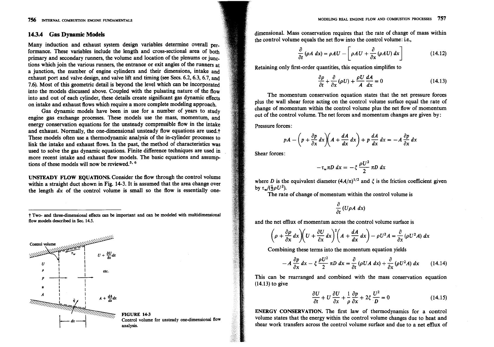
Consider the flow through the control volume
within a straight duct shown in Fig.
14-3.
It is assumed that the area change over
the length dx of the control volume is small so the flow is essentially one-
t
Two- and three-dimensional effects
can
be
important and can
be
modeled
with
multidimensional
flow models
described
in
Sec.
14.5.
I
P
I
I
etc.
I
P-
-
I
I
FIGURE
143
Control volume for unsteady onedimensional flow
I
I
analysis.
I
MODELING
REAL
ENGINE FLOW AND COMBUSTION
PROCESSES
757
i
dimensional. Mass conservation requires that the rate of change of mass within
the control volume equals the net flow into the control volume: i.e.,
a
-
(pA
dx)
=
pAU
-
at
I
Retaining only first-order quantities, this equation simplifies to
The momentum conservation equation states that the net pressure forces
plus the wall shear force acting on the control volume surface equal the rate of
change of momentum within the control volume plus the net flow of momentum
out of the control volume. The net forces and momentum changes are given by:
Pressure forces
:
Shear forces:
pUZ
-z,nD dx
=
-(
-
zD dx
2
where
D
is the equivalent diameter (~A/X)"~ and
(
is the friction coefficient given
by zwl(3~U2).
The rate of change of momentum within the control volume is
a
-
(UpA dx)
at
and the net emux of momentum across the control volume surface is
Combining these terms into the momentum equation yields
This can be rearranged and combined with the mass conservation equation
(14.13) to give
ENERGY CONSERVATION.
The first law
of thermodynamics for a control
volume states that the energy within the control volume changes due to heat and
shear work transfers across the control volume surface and due to
a
net efflux of
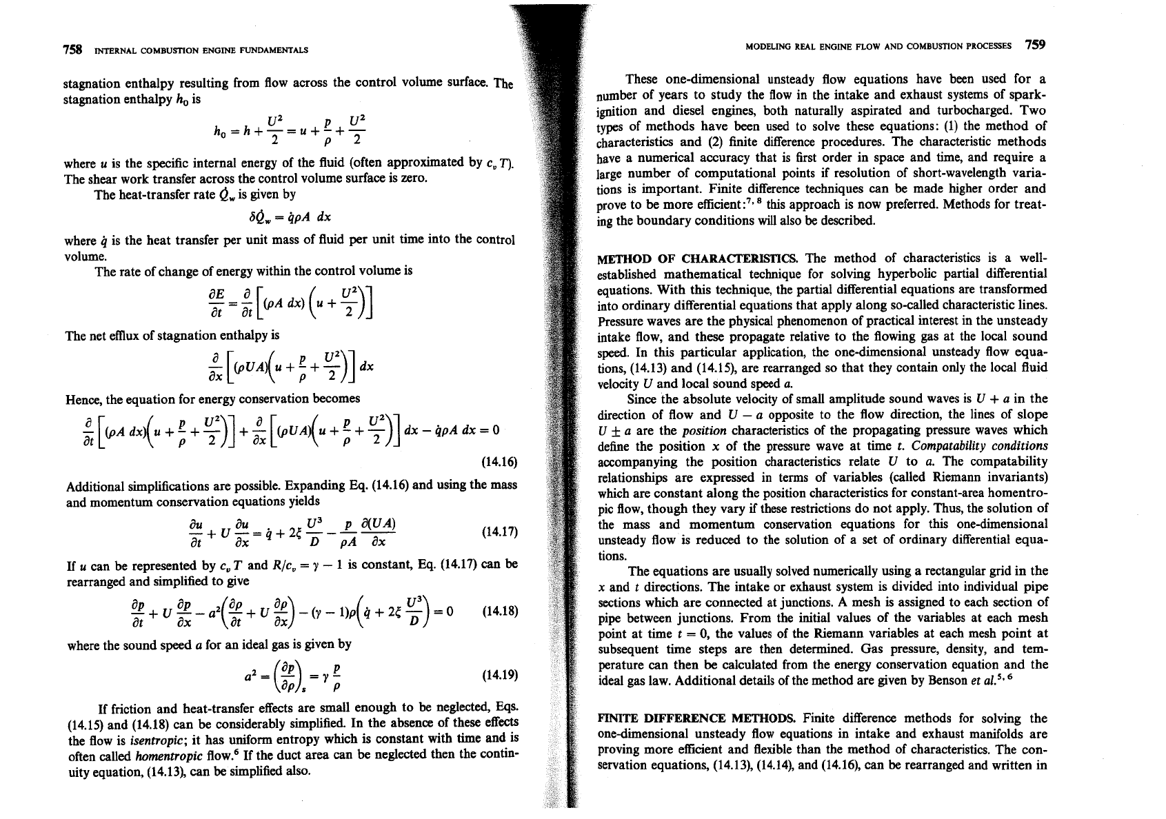
758
INTERNAL
COMBUSTION
ENGINE
FUNDAMENTALS
stagnation enthalpy resulting from flow across
the
control volume surface.
stabation enthalpy
h,
is
where
u
is the specific internal energy of the fluid (often approximated by
c,
7").
The shear work transfer across the control volume surface is zero.
The heat-transfer rate
0,
is given by
80,
=
qpA
dx
where
q
is the heat transfer per unit mass of fluid per unit time into the control
volume.
The rate of change of energy within the control volume is
The net efflux of stagnation enthalpy is
Hence, the equation for energy conservation becomes
Additional simplifications are possible. Expanding Eq. (14.16) and using the mass
and momentum conservation equations yields
If
u
can be represented by
c,
T
and
Rlc,
=
y
-
1 is constant, Eq. (14.17) can be
rearranged and simplified to give
where the sound speed
a
for an ideal gas is given by
If friction and heat-transfer effects are small enough to be neglected, Eqs.
(14.15) and (14.18) can be considerably simplified. In the absence of these effects
the flow is
isentropic;
it has uniform entropy which is constant with time and is
often called
hornentropic
flow.6 If the duct area can be neglected then the contin-
uity equation, (14.13), can be simplified also.
MODELING
REAL
ENGINE
FLOW
AND
COMBUSTION
PROCESSES
759
These one-dimensional unsteady flow equations have been used for a
number of years to study the flow in the intake and exhaust systems of spark-
ignition and diesel engines, both naturally aspirated and turbocharged. Two
types of methods have been used to solve these equations: (1) the method of
characteristics and (2) finite difference procedures. The characteristic methods
have a numerical accuracy that is first order in space and time, and require a
large number of computational points if resolution of short-wavelength varia-
tions is important. Finite difference techniques can be made higher order and
prove to be more
efEcient:7*8 this approach is now preferred. Methods for treat-
ing the boundary conditions will also
be
described.
METHOD OF CHARACERISTICS.
The method of characteristics is
a
well-
established mathematical technique for solving hyperbolic partial differential
equations. With this technique, the partial differential equations are transformed
into ordinary differential equations that apply along so-called characteristic lines.
Pressure waves are the physical phenomenon of practical interest in the unsteady
intake flow, and these propagate relative to the flowing gas at the local sound
speed. In this particular application, the one-dimensional unsteady flow equa-
tions, (14.13) and
(14.15), are rearranged so that they contain only the local fluid
velocity
U
and local sound speed
a.
Since the absolute velocity of small amplitude sound waves is
U
+
a
in the
direction of flow and
U
-
a
opposite to the flow direction, the lines of slope
U
+
a
are the
position
characteristics of the propagating pressure waves which
define the position
x
of the pressure wave at time
t.
Cornpatability conditions
accompanying the position characteristics relate
U
to
a.
The compatability
relationships are expressed in terms of variables (called Riemann invariants)
which are constant along the position characteristics for constant-area
homentro-
pic flow, though they vary
if
these restrictions do not apply. Thus, the solution of
the mass and momentum conservation equations for this one-dimensional
unsteady flow is reduced to the solution of a set of ordinary differential equa-
tions.
The equations are usually solved numerically using a rectangular grid in the
x
and
t
directions. The intake or exhaust system is divided into individual pipe
sections which are connected at junctions. A mesh is assigned to each section of
pipe between junctions. From the initial values of the variables at each mesh
point at time
t
=
0,
the values of the Riemann variables at each mesh point at
subsequent time steps are then determined. Gas pressure, density, and tem-
perature can then be calculated from the energy conservation equation and the
ideal gas law. Additional details of the method are given by Benson
et al.5.6
FINITE
DIFFERENCE
METHODS.
Finite difference methods for solving the
onedimensional unsteady flow equations in intake and exhaust manifolds are
proving more
efficient and flexible than the method of characteristics. The con-
servation equations, (14.13), (14.14), and (14.16), can be rearranged and written in
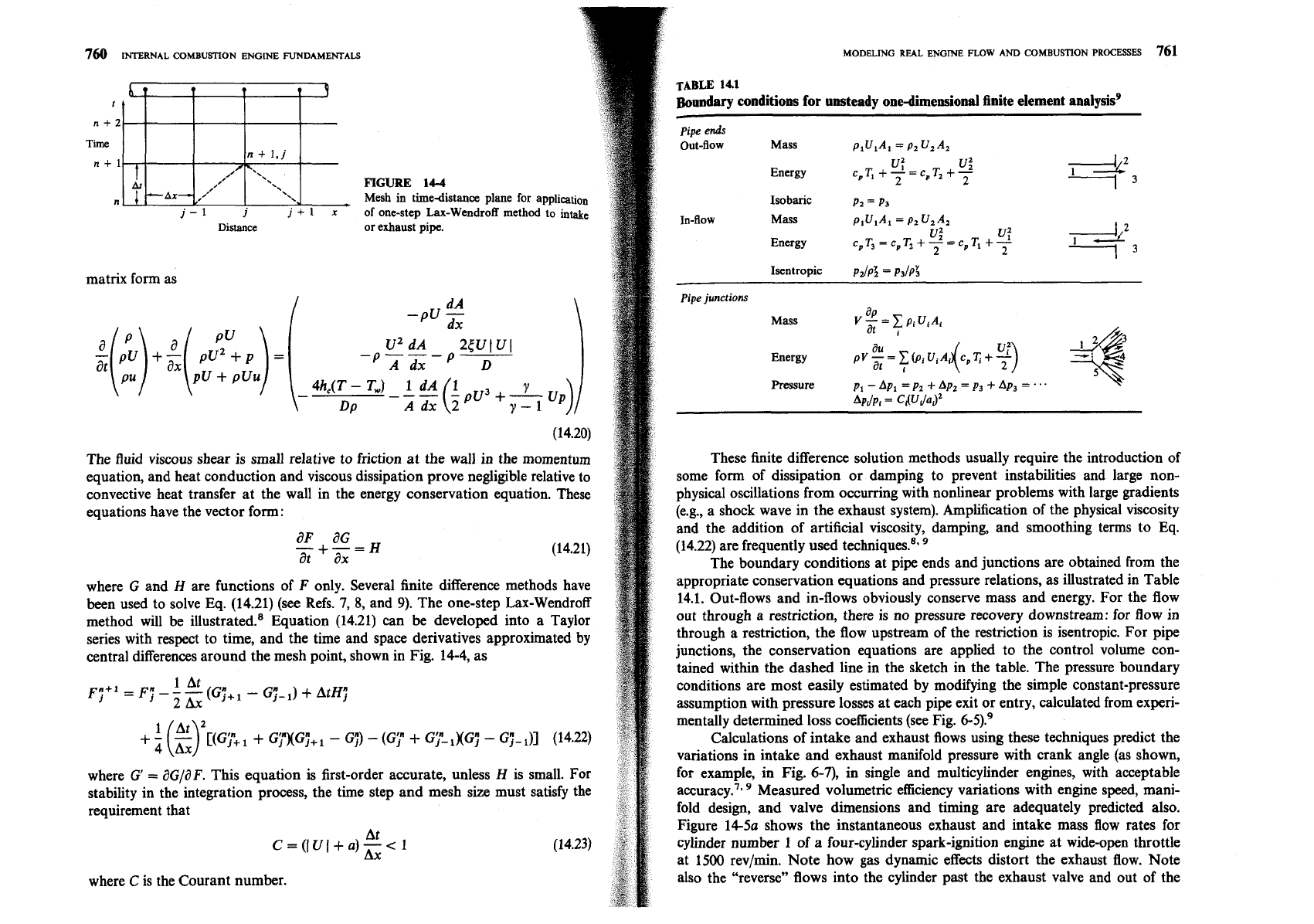
6
0
t
t
3
n+2
Time
n+
1,j
n+l
,,/
\'-
At
*\
I
&AX-
/"
\'.
n.
'xu
-
j-1
j
j+l
x
Distance
matrix form as
INTERNAL
COMBUSTION ENGINE
FUNDAMENTALS
FIGURE
14-4
Mesh in timedistance plane for application
of one-step Lax-Wendroff method to intake
or exhaust pipe.
at
The fluid viscous shear is small relative to friction at the wall in the momentum
equation, and heat conduction and viscous dissipation prove negligible relative to
convective heat transfer at the wall in the energy conservation equation. These
equations have the vector form:
aF aG
--+-=H
at
ax
where G and H are functions of F only. Several finite difference methods have
been used to solve Eq. (14.21) (see Refs.
7,
8,
and
9).
The one-step Lax-Wendroff
method will be illu~trated.~ Equation (14.21) can
be
developed into a Taylor
series with respect to time, and the time and space derivatives approximated by
central differences around the mesh point, shown in Fig. 14-4, as
1 At
FYf'
=
F;
-
-
-
2Ax
(GY+
1
-
GjA-
')
+
AtH;
[(Gy+
+
Gy)(G;+
1
-
G;)
-
(Gy
+
Gy- ,KG;
-
GY-
(14.22)
where
G'
=
BGJdF. This equation is first-order accurate, unless
H
is small. For
stability in the integration process, the time step and mesh size must satisfy the
requirement that
where
C
is the Courant number.
[
TABLE
14.1
Boundary conditions for unsteady onedimensional finite element analysis9
pipe
ends
Out-flow Mass
~lUlAl= P2 U2A2
Energy
UZ
v
:
cPTl +L=~,T2
+-
2
2
Ad2
-3
Isobaric
PZ
=
P3
In-flow Mass
plUlA1
=
P2 UzAz
Energy
u
v:
c, T3
=
c,
T,
+
-2
=
C,
TI
+
-
2
2
l3
Isentropic
p21p:
=
P~/P$
pipe
junctions
.
-
Mass
ap
V-=XP~U,A~
at
,
Energy
Pressure
p1
-
Apl
=
pz
+
Ap2
=
p3
+
Ap3
=
.
..
These finite difference solution methods usually require the introduction of
some form of dissipation or damping to prevent instabilities and large non-
physical oscillations from occurring with nonlinear problems with large gradients
(e.g., a shock wave in the exhaust system). Amplification of the physical viscosity
and the addition of artificial viscosity, damping, and smoothing terms to Eq.
(14.22) are frequently used
technique^.^,
The boundary conditions at pipe ends and junctions are obtained from the
appropriate conservation equations and pressure relations, as illustrated in Table
14.1. Out-flows and in-flows obviously conserve mass and energy. For the flow
out through a restriction, there is no pressure recovery downstream: for flow in
through a restriction, the flow upstream of the restriction is isentropic. For pipe
junctions, the conservation equations are applied to the control volume con-
tained within the dashed line in the sketch in the table. The pressure boundary
conditions are most easily estimated by modifying the simple constant-pressure
assumption with pressure losses at each pipe exit or entry, calculated from experi-
mentally determined loss coefficients (see Fig. 6-5).'
Calculations of intake and exhaust flows using these techniques predict the
variations in intake and exhaust manifold pressure with crank angle (as shown,
for example, in Fig.
6-7),
in single and multicylinder engines, with acceptable
accuracy.'. Measured volumetric efficiency variations with engine speed, mani-
fold design, and valve dimensions and timing are adequately predicted also.
Figure 14% shows the instantaneous exhaust and intake mass flow rates for
cylinder number 1 of a four-cylinder spark-ignition engine at wide-open throttle
at 1500
rev/min. Note how gas dynamic effects distort the exhaust flow. Note
also the "reverse" flows into the cylinder past the exhaust valve and out of the
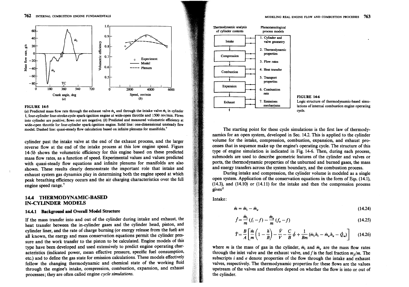
Experiment
-
Model
,c
0.6
----
Plenum
Crank angle, deg
(4
Speed,
revlmin
(b)
FIGURE
14-5
(a)
Predicted mass flow rate through the exhaust valve
me
and through the intake valve
m,
in cylinder
1,
four-cylinder four-stroke-cycle spark-ignition engine at wi*open throttle and
1500
rev/min. Flows
into cylinder are positive; flows out are negative.
(b)
Predicted and measured volumetric efficiency at
wide-open throttle for fow-cylinder spark-ignition engine. Solid line: one-dimensional unsteady flow
model. Dashed line: quasi-steady flow calculation based on infinite plenums for manifolds.'
cylinder past the intake valve at the end of the exhaust process, and the larger
reverse flow at the end of the intake process at this low engine speed. Figure
14-5b shows the volumetric efficiency for this engine based on these predicted
mass flow rates, as a function of speed. Experimental values and values predicted
with quasi-steady flow equations and infinite plenums for manifolds are also
shown. These results clearly demonstrate the important role that intake and
exhaust system gas dynamics play in determining both the engine speed at which
peak breathing efficiency occurs and the air charging characteristics over the full
engine speed range.'
14.4
THERMODYNAMIC-BASED
IN-CYLINDER
MODELS
14.4.1
Background and Overall Model Structure
If the mass transfer into and out of the cylinder during intake and exhaust, the
heat transfer between the in-cylinder gases and the cylinder head, piston, and
cylinder liner, and the rate of charge burning (or energy release from the fuel) are
all known, the energy and mass conservation equations permit the cylinder pres-
sure and the work transfer to the piston to
be
calculated. Engine models of this
type have been developed and used extensively to predict engine operating char-
acteristics (indicated power, mean effective pressure, specific fuel consumption,
etc.) and to define the gas state for emission calculations. These models effectively
follow the changing thermodynamic and chemical state of the working fluid
through the engine's intake, compression, combustion, expansion, and exhaust
processes; they are often called engine
cycle simulations.
MODELING
REAL
ENGINE
FLOW
AND
COMBUSTION
PROCESSES
763
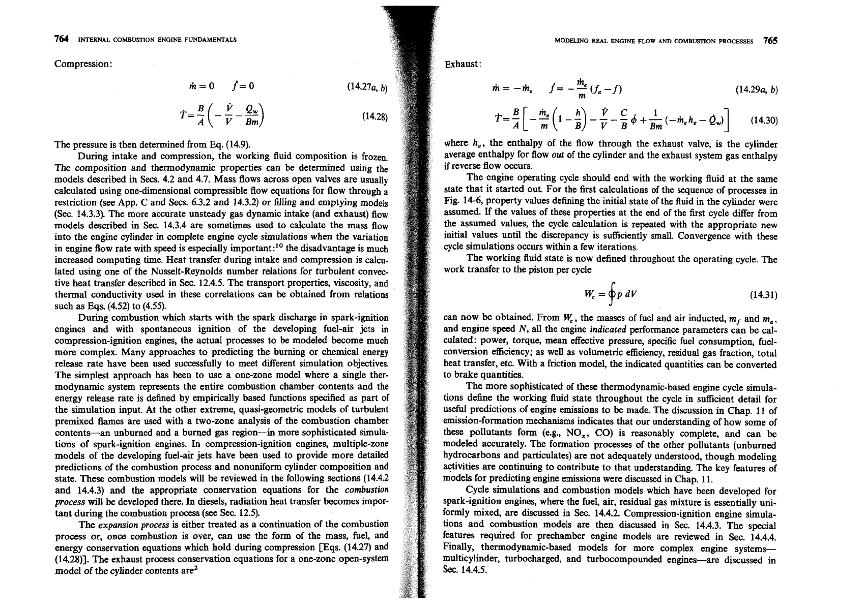
Thermodynamic analysis
Phenomenological
of
cylinder
contents
process models
valve geomeuy
2.
Thermodynamic
Compression
properties
3.
Flow
rates
I
Combustion
a
'.
5.
Transport
properties
6.
Combustion
rate
Exhaust
7.
Emissions
mechanisms
4
FIGURE
14-6
Logic structure of thermodynamic-based simu-
lations of internal combustion engine operating
cycle.
The starting point for these cycle simulations is the first law of thermody-
namics for an open system, developed in Sec. 14.2. This is applied to the cylinder
volume for the intake, compression, combustion, expansion, and exhaust pro-
cesses that in sequence make up the engine's operating cycle. The structure of this
type of engine simulation is indicated in Fig. 14-6. Then, during each process,
submodels are used to describe geometric features of the cylinder and valves or
ports, the thermodynamic properties of the unburned and burned gases, the mass
and energy transfers across the system boundary, and the combustion process.
During intake and compression, the cylinder volume is modeled as a single
open system. Application of the conservation equations in the form of Eqs.
(14.1),
(14.3), and (14.10) or (14.11) for the intake and then the compression process
givesZ
Intake:
where
m
is the mass of gas
in
the cylinder,
mi
and
me
are the mass flow rates
through the inlet valve and the exhaust valve, and
f
is the fuel fraction
m,/m.
The
subscripts
i
and
e
denote properties of the flow through the intake and exhaust
valves, respectively. The thermodynamic properties for these flows are the values
upstream of the valves and therefore depend on whether the flow is into or out of
the cylinder.
764
INTERNAL
COMBUSTION
ENGINE
FUNDAMENTALS
Compression
:
The pressure is then determined from Eq. (14.9).
During intake and compression, the working fluid composition is frozen.
The composition and thermodynamic properties can be determined using the
models described in Secs. 4.2 and 4.7. Mass flows across open valves are usually
calculated using one-dimensional compressible flow equations for flow through a
restriction (see App.
C
and Secs. 6.3.2 and 14.3.2) or filling and emptying models
(Sec. 14.3.3). The more accurate unsteady gas dynamic intake (and exhaust) flow
models described in
Sec. 14.3.4 are sometimes used to calculate the mass flow
into the engine cylinder in complete engine cycle simulations when the variation
in engine flow rate with speed is especially important
:lo
the disadvantage
is
much
increased computing time. Heat transfer during intake and compression is calcu-
lated using one of the Nusselt-Reynolds number relations for turbulent convec-
tive heat transfer described in
Sec. 12.4.5. The transport properties, viscosity, and
thermal conductivity used in these correlations can be obtained from relations
such as Eqs. (4.52) to (4.55).
During combustion which starts with the spark discharge in spark-ignition
engines and with spontaneous ignition of the developing fuel-air jets
in
compression-ignition engines, the actual processes to
be
modeled become much
more complex. Many approaches to predicting the burning or chemical energy
release rate have been used successfully to meet different simulation objectives.
The simplest approach has been to use a one-zone model where a single ther-
modynamic system represents the entire combustion chamber contents and the
energy release rate is defined by empirically based functions specified as part of
the simulation input. At the other extreme, quasi-geometric models of turbulent
premixed flames are used with a two-zone analysis of the combustion chamber
contents-an unburned and a burned gas region-in more sophisticated simula-
tions of spark-ignition engines. In compression-ignition engines, multiple-zone
models of the developing fuel-air jets have been used to provide more detailed
predictions of the combustion process and nonuniform cylinder composition and
state. These combustion models will
be
reviewed in the following sections (14.4.2
and 14.4.3) and the appropriate conservation equations for the
combustion
process
will
be
developed there. In diesels, radiation heat transfer becomes impor-
tant during the combustion process (see Sec. 12.5).
The
expansion process
is either treated as a continuation of the combustion
process or, once combustion is over, can use the form of the mass, fuel, and
energy conservation equations which hold during compression [Eqs. (14.27) and
(14.2811. The exhaust process conservation equations for a one-zone open-system
model of the cylinder contents are2
MODELING REAL ENGINE FLOW AND COMBUSTION PROCESSES
765
Exhaust
:
where he, the enthalpy of the flow through the exhaust valve, is the cylinder
average enthalpy for flow
out
of the cylinder and the exhaust system gas enthalpy
if
reverse flow occurs.
The engine operating cycle should end with the working fluid at the same
state that it started out. For the first calculations of the sequence of processes in
Fig. 14-6, property values defining the initial state of the fluid in the cylinder were
assumed. If the values of these properties at the end of the first cycle differ from
the assumed values, the cycle calculation is repeated with the appropriate new
initial values until the discrepancy is sufficiently small. Convergence with these
cycle simulations occurs within a few iterations.
The working fluid state is now defined throughout the operating cycle. The
work transfer to the piston per cycle
can now
be
obtained. From
W,
,
the masses of fuel and air inducted, m, and
ma,
and engine speed
N,
all the engine
indicated
performance parameters can be cal-
culated: power, torque, mean effective pressure, specific fuel consumption, fuel-
conversion efficiency; as well as volumetric efficiency, residual gas fraction, total
heat transfer, etc. With a friction model, the indicated quantities can
be
converted
to brake quantities.
The more sophisticated of these thermodynamic-based engine cycle simula-
tions
define the working fluid state throughout the cycle in sufficient detail for
useful predictions of engine emissions to be made. The discussion in Chap. 11 of
emission-formation mechanisms indicates that our understanding of how some of
these pollutants form
(e.g., NO,, CO) is reasonably complete, and can be
modeled accurately. The formation processes of the other pollutants (unburned
hydrocarbons and particulates) are not adequately understood, though modeling
activities are continuing to contribute to that understanding. The key features of
models for predicting engine emissions were discussed in Chap. 11.
Cycle simulations and combustion models which have been developed for
spark-ignition engines, where the fuel, air, residual gas mixture is essentially uni-
formly mixed, are discussed in
Sec. 14.4.2. Compression-ignition engine simula-
tions and combustion models are then discussed in Sec. 14.4.3. The special
features required for prechamber engine models are reviewed in Sec. 14.4.4.
Finally, thermodynamic-based models for more complex engine systems-
multicylinder, turbocharged, and turbocompounded engines-are discussed in
Sec.
14.4.5.
that permit major simplifying assumptions for thermodynamic modeling ire:
(t)
the fuel, air, residual gas charge is essentially uniformly premixed; (2) the volume
occupied by the reaction zone where the fuel-air oxidation process actually
occurs is normally small compared with the clearance volume-the flame is a
thin reaction sheet even though it becomes highly wrinkled and convoluted by
the turbulent flow as it develops (see Sec. 9.3); thus (3) for thermodynamic
analysis, the contents of the combustion chamber during combustion can
be
analyzed as two zones-an unburned and a burned zone.
Useful combustion chamber design information can
be
generated with
simple geometric models of the flame. In the absence of strong swirl, the surface
which defines the leading edge of the flame can be approximated by a portion of
the surface of a sphere. Thus the mean burned gas front can also be approx-
imated by a sphere. Then, for a given combustion chamber shape and assumed
flame center location
(e.g., the spark plug), the spherical burning area
A,
[see
Eq.
(9.40)], the burned gas volume
V,
[see Eq. (9.3911, and the combustion chamber
surface "wetted" by the burned gases can
be
calculated for a given flame radius
r,
and piston position (defined by crank angle) from purely geometric consider-
ations.? The practical importance of such "model" calculations is that (1) the
mass burning rate for a given burning speed
S,
(which depends on local turbu-
lence and mixture composition) is proportional to the spherical burning area
A,
as given by Eq. (9.44); (2) the heat transfer occurs largely between the burned
gases and the walls and is proportional to the chamber surface area wetted by the
burned gases
A,,
[see
Eq. (12.2111. Using the fact that the density ratio across
the flame
p
Jp, is approximately constant and equal to
4,
the unburned and
burned gas volumes and
h
can be related to the unburned and burned mass
fractions (1
-
x,)
and
x,,
respectively.
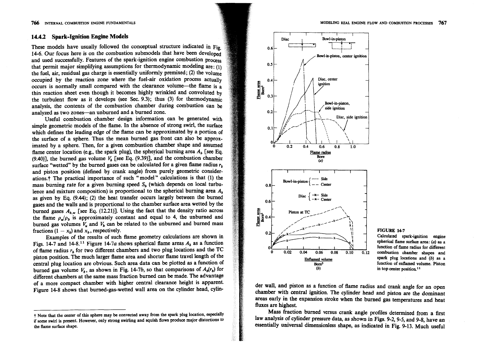
Examples of the results of such flame geometry calculations are shown in
Figs. 14-7 and
14.8." Figure 14-7a shows spherical flame areas
A,
as a function
of flame radius
r,
for two different chambers and two plug locations and the TC
piston position. The much larger flame area and shorter flame travel length of the
central plug location are obvious. Such area data can be plotted as a function of
burned gas volume
5,
as shown in Fig. 14-7b, so that comparisons of
Ab(rb)
for
different chambers at the same mass fraction burned can be made. The advantage
of a more compact chamber with higher central clearance height is apparent.
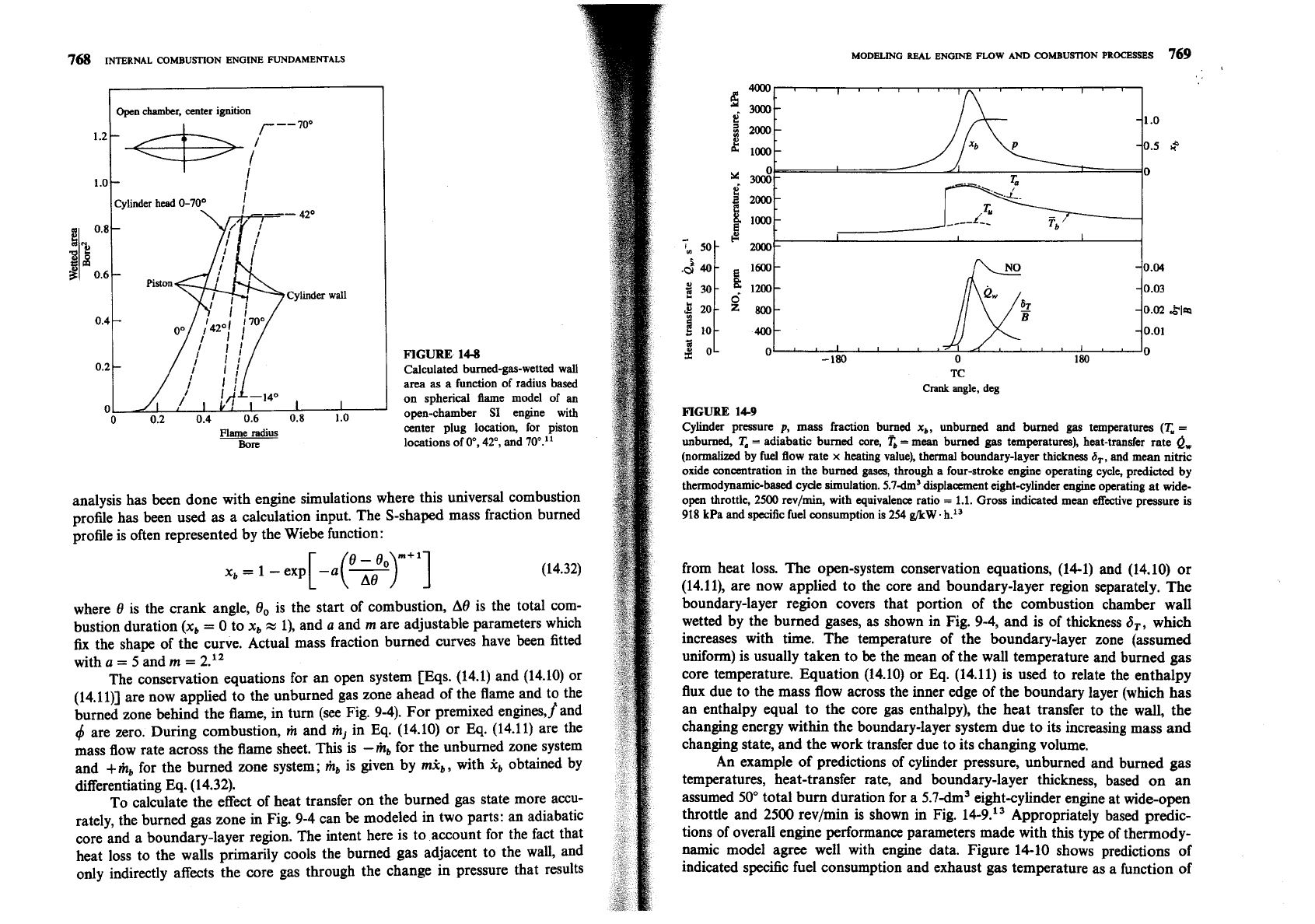
Figure
14-8 shows that burned-gas-wetted wall area on the cylinder head, cylin-
t
Note that the center of this sphere may
be
convected away from the spark plug location, especially
if
some swirl is p-t. However, only strong swirling and squish flows produce major distortions to
the flame surface shape.
766
INTERNAL
COMBUSTTON
ENGINE
FUNDAMENTALS
14.43
Spark-Ignition Engine Models
These models have usually followed the conceptual structure indicated in Fig.
14-6. Our focus here is on the combustion submodels that have been developed
and used successfully. Features of the spark-ignition engine combustion process
MODELING REAL ENGINE FLOW AND
COMBUSTlON
PROCESSES
767
0.4
-
/
/
Disc,
center
-
-
0.2
-
7-1.
Disc,
side
ignition
,
-
\
I
I
'\
I
'%
I
\
0 0.2 0.4 0.6 0.8 1.0
Bawl-in-piston
0.6
-*-
Center
FIGURE
14-7
Calculated spark-ignition engine
spherical flame surface area:
(a)
as
a
function of he radius for different
combustion chamber shapes and
spark plug locations and
(b)
as a
function of
entlamed
volume. Piston
in
top center position.
l1
der wall, and piston
as
a function of flame radius and crank angle for an open
chamber with central ignition. The cylinder head and piston are the dominant
areas early in the expansion stroke when the burned gas temperatures and heat
fluxes are highest.
Mass fraction burned versus crank angle profiles determined from a first
law analysis of cylinder pressure data, as shown
in
Fig.
9-2,9-5,
and 9-8, have an
essentially universal dimensionless shape, as indicated in Fig. 9-13. Much useful
768
INTERNAL
COMBUSTION
ENGINE FUNDAMENTALS
4Z0
Piston
Cylinder
wall
FIGURE 14-8
Calculated burned-gas-wetted wall
-.-
-.
.
.
.
Flame
radius
center plug location, for piston
Bore
locations of O0,
42",
and 70•‹."
2
3
0
analysis has been done with engine simulations where this universal combustion
profile has been used
as
a calculation input. The S-shaped mass fraction burned
~rofile is often represented by the Wiebe function:
where 8 is the crank angle,
8, is the start of combustion, A8 is the total com-
bustion duration (x,
=
0 to x,
m
I), and
a
and m are adjustable parameters which
fix
the shape of the curve. Actual mass fraction burned curves have been fitted
with
a
=
5 and
m
=
2."
The conservation equations for an open system [Eqs. (14.1) and (14.10) or
(14.11)] are now applied to the unburned gas zone ahead of the flame and to the
burned zone behind the flame, in turn (see Fig. 9-4). For premixed engines,
f
and
$
are zero. During combustion, m and m, in
Eq.
(14.10) or
Eq.
(14.11) are the
mass flow rate across the flame sheet. This is -mb for the unburned zone system
and +mb for the burned zone system;
m,
is given by mk,, with
5
obtained by
differentiating Eq. (14.32).
To calculate the effect of heat transfer on the burned gas state more accu-
rately, the burned gas zone in Fig. 9-4 can
be
modeled in two parts: an adiabatic
core and a boundary-layer region. The intent here is to account for the fact that
heat loss to the walls primarily cools the burned gas adjacent to the wall, and
only indirectly affects the core gas through the change in pressure that results
i
/
/,$-140
I
~
MODELING
ReAL
ENGINE
FLOW
AND
COMBUSTION
PROCESSES
769
area
as
a function of radius based
on spherical flame model of an
TC
Crank
angle, deg
n
n
7
o
A
0.6
0.8 1.0
open-chamber
SI
engine
with
FIGURE
14-9
Cylinder pressure
p,
mass fraction burned
x,,
unburned and burned
gas
temperatures
(T,
=
unburned,
T,
=
adiabatic burned core,
'i;
=
mean burned gas temperatures), heat-transfer rate
0,
(normalized by fuel 5ow rate
x
heating value),
thermal
boundary-layer thickness
a,,
and mean nitric
oxide concentration in the burned gases, through a four-stroke engine operating cycle, predicted by
thermodynamic-based cycle simulation. 5.7-dm3 displacement eight-cylinder engine operating at wide-
open throttle,
2500
revlmin, with equivalence ratio
=
1.1.
Gross indicated mean effective pressure is
918
kPa and specific fuel consumption is
254
g/kW
h.I3
from heat loss. The open-system conservation equations, (14-1) and (14.10) or
(14.11), are now applied to the core and boundary-layer region separately. The
boundary-layer region covers that portion of the combustion chamber wall
wetted by the burned gases, as shown in Fig. 9-4, and is of thickness
a,,
which
increases with time. The temperature of the boundary-layer zone (assumed
uniform) is usually taken to
be
the mean of the wall temperature and burned gas
core temperature. Equation (14.10) or
Eq.
(14.11) is used to relate the enthalpy
flux due to the mass flow across the inner edge of the boundary layer (which has
an enthalpy equal to the core gas enthalpy), the heat transfer to the wall, the
changing energy within the boundary-layer system due to its increasing mass and
changing state, and the work transfer due to its changing volume.
An example of predictions of cylinder pressure, unburned and burned gas
temperatures, heat-transfer rate, and
boundary-layer thickness, based on an
assumed 50" total burn duration for a
5.7dm3
eight-cylinder engine at wide-open
throttle and 2500 rev/min is shown in Fig. 14-9.13 Appropriately based predic-
tions of overall engine performance parameters made with this type of thermody-
namic model agree well with engine data. Figure 14-10 shows predictions of
indicated
spec5c fuel consumption and exhaust gas temperature as a function of
