Heywood J.B. Internal Combustion Engines Fundamentals
Подождите немного. Документ загружается.

630
INTERNAL
COMBUSTION ENGINE
FUNDAMENTALS
POLLUTANT
FORMATION
AND
CONTROL
631
pherule. The crystallites are arranged with their planes more or less
he particle surface. This structure of unordered layers is called turbo-
static. The spherules, 10 to 50 nm in diameter, are fused together to form par-
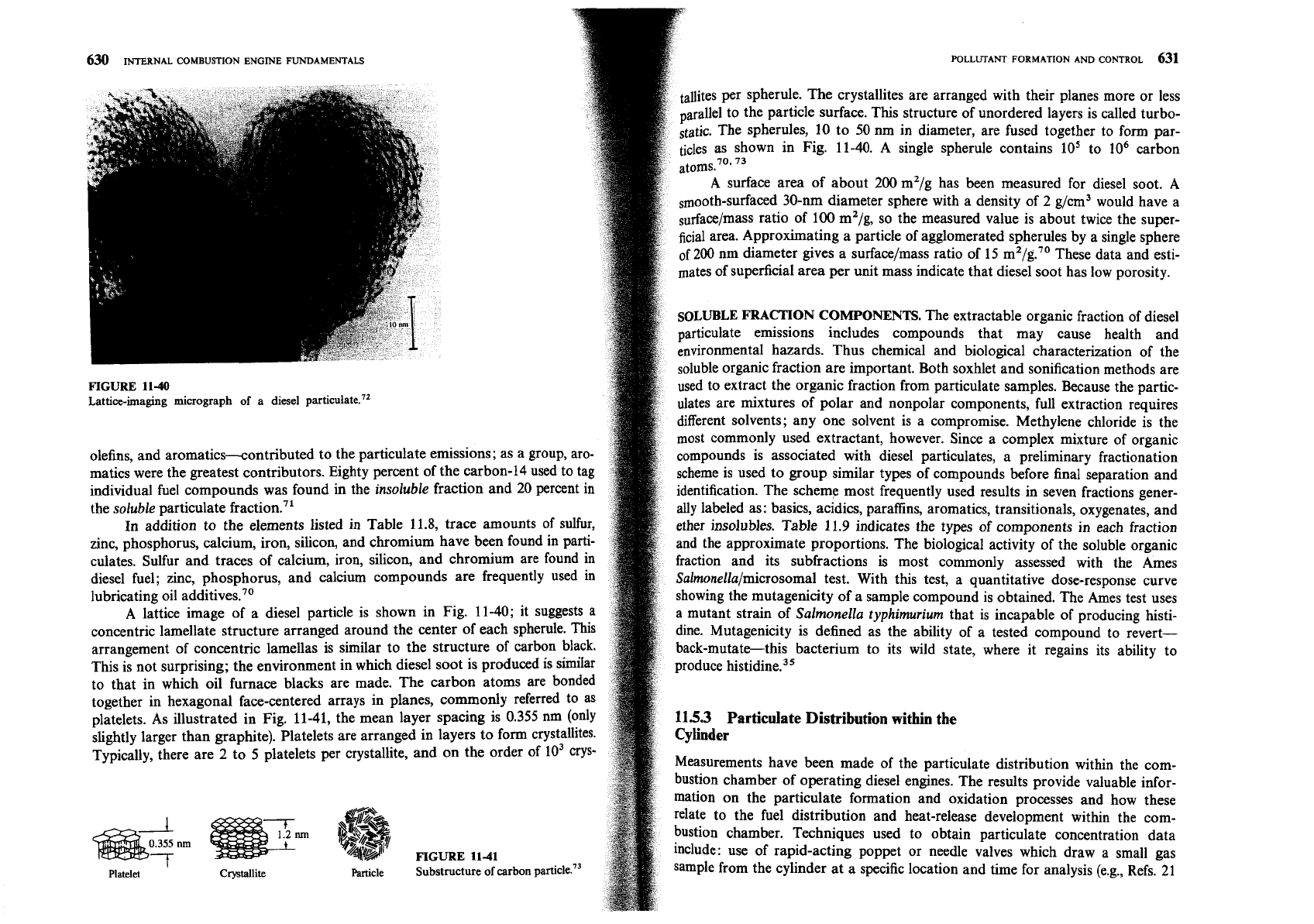
own in Fig. 11-40. A single spherule contains lo5 to lo6 carbon
A surface area of about 200 m2/g has been measured for diesel soot. A
smooth-surfaced 30-nm diameter sphere with a density of 2 g/cm3 would have a
surface/mass ratio of 100 m2/g, so the measured value is about twice the super-
ficial area. Approximating a particle of agglomerated spherules by a single sphere
of
200 nm diameter gives a surface/mass ratio of 15 m2/g.70 These data and esti-
mates of superficial area per unit mass indicate that diesel soot has low porosity.
SOLUBLE
FRACTION
COMPONENTS.
The extractable organic fraction of diesel
particulate emissions includes compounds that may cause health and
environmental hazards. Thus chemical and biological characterization of the
soluble organic fraction are important. Both soxhlet and sonification methods are
FIGURE
11-40
used to extract the organic fraction from particulate samples. Because the partic-
Lattice-imaging micrograph of a diesel particulate."
ulates are mixtures of polar and nonpolar components, full extraction requires
different solvents; any one solvent is a compromise. Methylene chloride is the
most commonly used extractant, however. Since a complex mixture of organic
olefins, and aromatics-contributed to the particulate emissions; as a group, aro- compounds is associated with diesel particulates, a preliminary fractionation
matics were the greatest contributors. Eighty percent of the carbon-14 used to tag scheme is used to group similar types of compounds before final separation and
individual fuel compounds was found
in
the insoluble fraction and 20 percent in
identification. The scheme most frequently used results in seven fractions gener-
the soluble particulate fra~tion.~'
ally labeled as: basics, acidics, paraffins, aromatics, transitionals, oxygenates, and
In addition to the elements listed in Table 11.8, trace amounts of sulfur,
ether insolubles.
Table
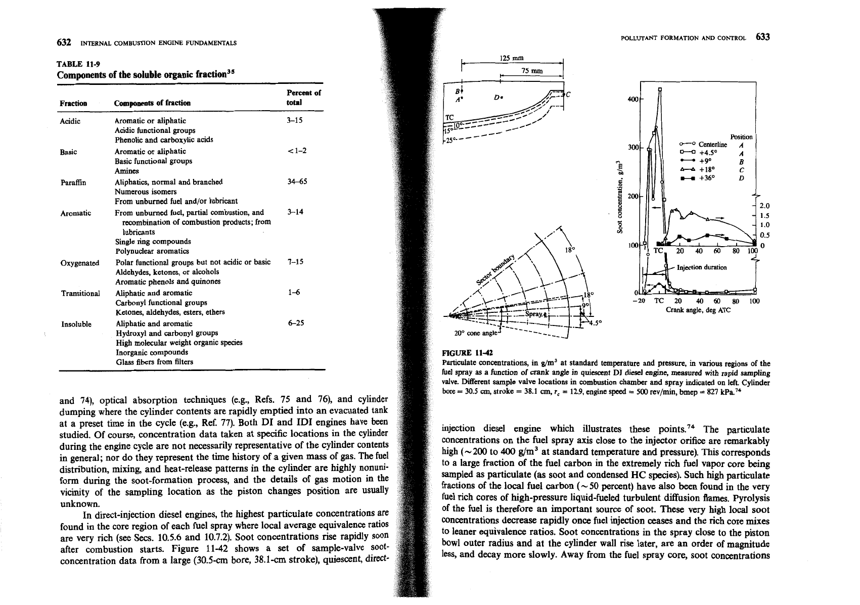
11.9 indicates the types of components in each fraction
zinc, phosphorus, calcium, iron, silicon, and chromium have been found in parti- and the approximate proportions. The biological activity of the soluble organic
culates. Sulfur and traces of calcium, iron, silicon, and chromium are found in fraction and its subfractions is most commonly assessed with the Ames
diesel fuel; zinc, phosphorus, and calcium compounds are frequently used in Salmonella/microsomal test. With this test, a quantitative dose-response curve
lubricating oil additives70
showing the mutagenicity of a sample compound is obtained. The Ames test uses
A
lattice image of a diesel particle is shown in Fig. 11-40; it suggests a
a mutant strain of Salmonella typhimurium that is incapable of producing histi-
concentric lamellate structure arranged around the center of each spherule. This
dine. Mutagenicity is defined as the ability of a tested compound to
revert-
arrangement of concentric lamellas is similar to the structure of carbon black.
back-mutate-this bacterium to its wild state, where it regains its ability to
This is not surprising; the environment in which diesel soot is produced is similar
produce histidine.j5
to that in which oil furnace blacks are made. The carbon atoms are bonded
together in hexagonal face-centered arrays in planes, commonly referred to as
platelets. As illustrated in Fig. 11-41, the mean layer spacing is 0.355 nm (only
115.3
Particulate Distribution within the
slightly larger than graphite). Platelets are arranged in layers to form crystallites.
Typically, there are
2
to
5
platelets per crystallite, and on the order of
lo3
crys-
Measurements have been made of the particulate distribution within the com-
bustion chamber of operating diesel engines. The results provide valuable infor-
mation on the particulate formation and oxidation processes and how these
relate to the fuel distribution and heat-release development within the com-
bustion chamber. Techniques used to obtain particulate concentration data
FIGURE 11-41
include: use of rapid-acting poppet or needle valves which draw a small gas
Platelet
Crystdlite
Mcle Substructure of carbon
sample from the cylinder at a specific location and time for analysis (e.g., Refs. 21
Acidic
Basic
Paraffin
Aromatic
Oxygenated
Transitional
Insoluble
Aromatic or aliphatic
Acidic functional groups
Phenolic and
carboxylic acids
Aromatic or aliphatic
Basic functional groups
Amines
Aliphatics, normal and branched
Numerous isomers
From unburned fuel and/or lubricant
From unburned fuel, partial combustion, and
recombination of combustion products; from
lubricants
Single ring compounds
Polynuclear aromatics
Polar functional groups but not acidic or basic
Aldehydes, ketones, or alcohols
Aromatic phenols and
quinones
Aliphatic and aromatic
Carbonyl functional groups
Ketones, aldehydes, esters, ethers
Aliphatic and aromatic
Hydroxyl and carbonyl groups
High molecular weight organic species
Inorganic compounds
Glass
fibers
from filters
632
INTERNAL
COMBUSTION
ENGINE
FUNDAMENTALS
TABLE
113
Components of the
soluble
organic fraction3'
Percent
of
Fraction
Componeots
of fraction
total
3-15
<
1-2
34-65
3-14
7-15
1-6
6-25
FIGURE
11-42
Pmculate concentrations, in g/m3
at
standard temperature and pressure,
in
vanous regons of the
fuel spray
as
a function of crank angle in quiescent
DI
dresel
engine, measured
with
rapid sampling
valve. Merent sample valve locations m
combustion
chamber and spray inhcated on left. Cylinder
bore
=
30.5
cm,
stroke
=
38.1
cm,
r,
=
12.9,
engine speed
=
500
rev/mn, bmep
=
827
kPa."
and
74),
optical absorption techniques (e.g., Refs.
75
and
76),
and cylinder
dumping where the cylinder contents are rapidly emptied into an evacuated tank
at a preset time in the cycle (e.g., Ref.
77).
Both DI and ID1 engines have been
studied. Of course, concentration data taken at specific locations in the cylinder
injection diesel engine which illustrates these
point^.'^
The particulate
during the engine cycle are not necessarily representative of the cylinder contents
concentrations on the fuel spray axis close to the injector orifice are remarkably
in general; nor do they represent the time history of
a
given mass of gas. The fuel
high
(-200
to
400
g/m3 at standard temperature and pressure). This corresponds
distribution, mixing and heat-release patterns in the cylinder are highly nonuni-
to a large fraction of the fuel carbon in the extremely rich fuel vapor core being
form during the soot-formation process, and the details of gas motion in the
sampled as particulate (as soot and condensed
HC
species). Such high particulate
vicinity of the sampling location as the piston changes position are usually
fractions of the local fuel carbon
(-
50
percent) have also been found in the very
unknown.
fuel rich cores of high-pressure liquid-fueled turbulent diffusion flames. Pyrolysis
In direct-injection diesel engines, the highest particulate concentrations
of the fuel is therefore an important source of soot. These very high local soot
found in the core region of each fuel spray where local average equivalence
concentrations decrease rapidly once fuel injection ceases and the rich core mixes
are very rich (see Secs.
10.5.6
and
10.7.2).
Soot concentrations
rise
rapidly
to leaner equivalence ratios. Soot concentrations in the spray close to the piston
after combustion starts. Figure
11-42
shows a set of sample-valve soot-
bowl outer radius and at the cylinder wall rise later, are an order of magnitude
concentration data from a large
(30.5-cm
bore,
38.1-cm
stroke), quiescent, direct-
less, and decay more slowly. Away from the fuel spray core, soot concentrations
-20
TC
20
40
60
80
100
Crank
angle, deg
ATC
634
INTERNAL
COMBUSTION
ENGINE
FUNDAMENTALS
POLLUTANT
FORMATION
AND
CONTROL
635
3E!
2!
2
Ignition
'j
'.
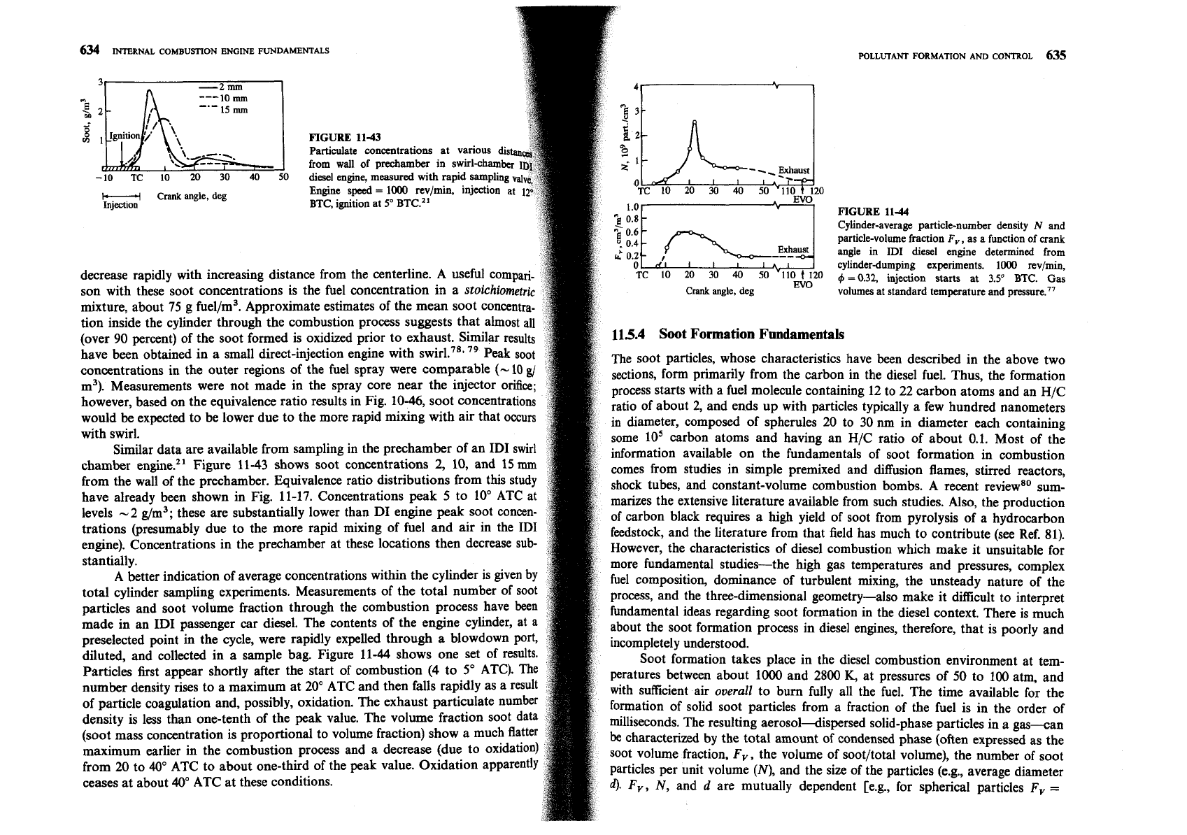
FIGURE
11-43
p
\,\'--:=--.
-10
TC
10
20
30
40
50
H
Crank
angle, deg
Injection
FIGURE
11-44
Cylinder-average particle-number density
N
and
particle-volume fraction
F,,
as a function
of
crank
angle in
ID1
diesel engine determined from
cylinder-dumping experiments.
1000
rev/min,
decrease rapidly with increasing distance from the centerline. A use
O
9
=
0.32,
injection starts at
3.5'
BTC.
Gas
son with these soot concentrations is the fuel concentration in a
~toichiometri~
Crank
angle, deg
volumes at standard temperature and pressure.77
mixture, about 75 g fuel/m3. Approximate estimates of the mean soot concentra-
tion inside the cylinder through the combustion process suggests that almost all
(over 90 percent) of the soot formed is oxidized prior to exhaust. Similar results
115.4
Soot
Formation Fundamentals
have been obtained in a small direct-injection engine with
79
Peak soot
The soot particles, whose characteristics have been described in the above two
concentrations in the outer regions of the fuel spray were comparable
(-
10
gi
sections, form primarily from the carbon in the diesel fuel. Thus, the formation
m3). Measurements were not made in the spray core near the injector orifice;
process starts with a fuel molecule containing 12 to 22 carbon atoms and an H/C
however, based on the equivalence ratio results in Fig. 10-46, soot concentrations
ratio of about 2, and ends up with particles typically a few hundred nanometers
would be expected to be lower due to the more rapid mixing with air that occurs
in diameter, composed of
spherules 20 to 30
nrn
in diameter each containing
with swirl.
some 10' carbon atoms and having an H/C ratio of about 0.1. Most of the
Similar data are available from sampling in the prechamber of an ID1 swirl
information available on the fundamentals of soot formation in combustion
chamber engine.21 Figure 11-43 shows soot concentrations 2, 10, and 15
mm
comes from studies in simple premixed and diffusion flames, stirred reactors,
from the wall of the prechamber. Equivalence ratio distributions from this study
shock tubes, and constant-volume combustion bombs. A recent reviews0 sum-
have already been shown in Fig. 11-17. Concentrations peak 5 to 10' ATC at
marizes the extensive literature available from such studies. Also, the production
levels -2 g/m3; these are substantially lower than DI engine peak soot concen-
of carbon black requires a high yield of soot from pyrolysis of a hydrocarbon
trations (presumably due to the more rapid mixing of fuel and air in the ID1
feedstock, and the literature from that field has much to contribute (see Ref. 81).
engine). Concentrations in the prechamber at these locations then decrease sub-
However, the characteristics of diesel combustion which make it unsuitable for
stantially.
more fundamental studies-the high gas temperatures and pressures, complex
A
better indication of average concentrations within the cylinder is given by
fuel composition, dominance of turbulent mixing, the unsteady nature of the
total cylinder sampling experiments. Measurements of the total number of soot
process, and the three-dimensional geometry-also make it
difficult to interpret
particles and soot volume fraction through the combustion process have been
fundamental ideas regarding soot formation in the diesel context. There is much
made in an ID1 passenger car diesel. The contents of the engine cylinder, at a
about the soot formation process in diesel engines, therefore, that is poorly and
preselected point in the cycle, were rapidly expelled through a
blowdown port,
incompletely understood.
diluted, and collected in a sample bag. Figure 11-44 shows one set of results.
Soot formation takes place in the diesel combustion environment at
tem-
Particles first appear shortly after the start of combustion
(4
to 5" ATC). The
peratures between about
1000
and 2800
K,
at pressures of 50 to 100 atm, and
number density rises to a maximum at 20" ATC and then falls rapidly as a result
with suflkient air
overall
to bum fully all the fuel. The time available for the
of particle coagulation and, possibly, oxidation. The exhaust particulate number
formation of solid soot particles from a fraction of the fuel is in the order of
density is less than one-tenth of the peak value. The volume fraction soot data
milliseconds. The resulting
aerosoldispersed solid-phase particles in a gas-an
(soot mass concentration is proportional to volume fraction) show a much flatter
be
characterized by the total amount of condensed phase (often expressed as the
maximum earlier in the combustion process and a decrease (due to oxidation)
soot volume fraction, Fv, the volume of soot/total volume), the number of soot
from 20 to 40" ATC to about one-third of the peak value. Oxidation apparently
particles per unit volume
(N),
and the size of the particles (e.g., average diameter
ceases at about 40" ATC at these conditions.
d).
F,,
N,
and
d
are mutually dependent [e.g., for spherical particles Fv
=
I
Nucleation
Dehydrogenation
Oxidation
636
INTERNAL COMBUSTION ENGINE FUNDAMENTALS
POLLUTANT
FORMATION
AND
CONTROL
637
(x/6)~d3], and any two of these variables characterize the system. It is mo
growth nor purely PAH growth would lead to soot particles which have
2,
in
convenient to consider
N
and Fv as the independent variables since they ea
the range 0.1 to 0.2. What is required is condensation of species with the right
relate to the "almost-separate" stages of soot particle generation (the source
hydrogen content, or condensation of species with higher hydrogen content
N) and soot particle growth (the source of Fv).
followed by dehydrogenation, or a combination of both these processes. Obvi-
These stages can be summarized as follows
ously some polyacetylenes and some PAH can satisfy these requirements, as
can saturated platelets (e.g., C27H2,
;
see Sec. 11.5.2). Surface growth reactions
1.
Particle formation, where the first condensed phase material arises from the
lead to an increase in the amount of soot (Fv) but the number of particles (N)
fuel molecules via their oxidation and/or pyrolysis products. These products
remains unchanged. The opposite is true for growth by coagulation, where the
typically include various unsaturated hydrocarbons, particularly acetylene and
particles collide and coalesce, which decreases N with
Fv
constant. Once
its higher analogues (C2,,H,), and polycyclic aromatic hydrocarbons
(PAH).
surface growth stops, continued aggregation of particles into chains and clus-
These two types of molecules are considered the most likely precursors of soot
ters can occur.
in flames. The condensation reactions of gas-phase species such as these lead
to the appearance of the first recognizable soot particles (often called nuclei).
These stages of particle generation and growth constitute the soot forma-
These first particles are very small
(d
<
2
m)
and the fotmation of large
tion process. At each stage in the process oxidation can occur where soot or soot
numbers of them involve negligible soot loading in the region of their forma-
precursors are burned in the presence of oxidizing species to form gaseous pro-
tion.
ducts such as CO and CO,. The eventual emission of soot from the engine will
2.
Particle growth, which includes both surface growth, coagulation, and aggre-
depend on the balance between these processes of formation and burnout. The
emitted soot is then subject to a further mass addition process as the exhaust
gation. Surface growth, by which the bulk of the solid-phase material is gener-
gases cool and are diluted with air. Adsorption into the soot particle surface and
ated, involves the attachment of gas-phase species to the suIface of particles
condensation to form new particles of hydrocarbon species in the exhaust gases
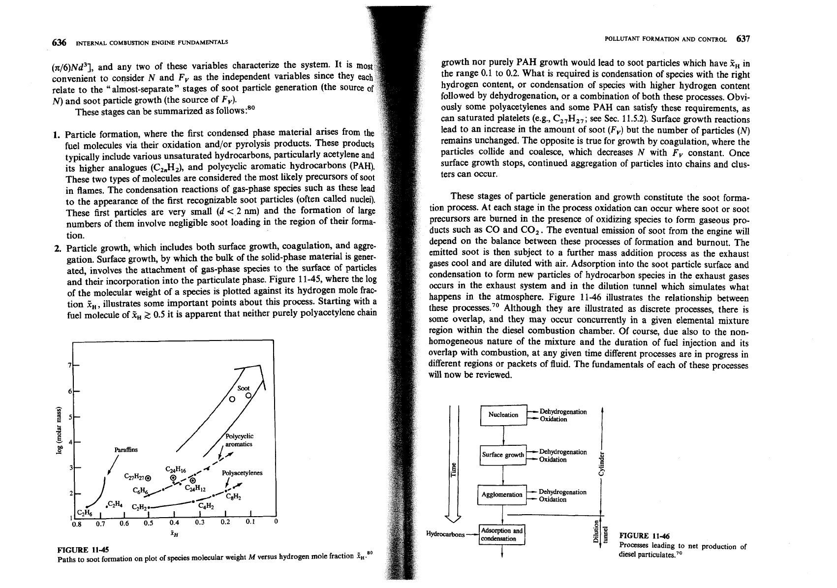
and their incorporation into the particulate phase. Figure
11-45,
where the 1%
of
the molecular weight of a species is plotted against its hydrogen mole frac-
occurs in the exhaust system and in the dilution tunnel which simulates what
tion
z,,
illustrates some important points about this process. Starting with a
happens in the atmosphere. Figure
11-46
illustrates the relationship between
fuel molecule of
f,~
0.5 it is apparent that neither purely polyacet~lene chain
these processes.70 Although they are illustrated as discrete processes, there is
some overlap, and they may occur concurrently in a given elemental mixture
region within the diesel combustion chamber. Of course, due also to the
non-
Oxidation
.-
-
u"
9
d
Oxidation
homogeneous nature of the mixture and the duration of fuel injection and its
overlap with combustion, at any given time different processes are in progress in
different regions or packets of fluid. The fundamentals of each of these processes
will now
be
reviewed.
0
condensation
FIGURE
11-46
FIGURE
11-45
Processes leading to net production of
paths to soot formation on plot of species molecular weight
M
versus hydrogen mole fraction
%t.80
diesel
particulate^.'^
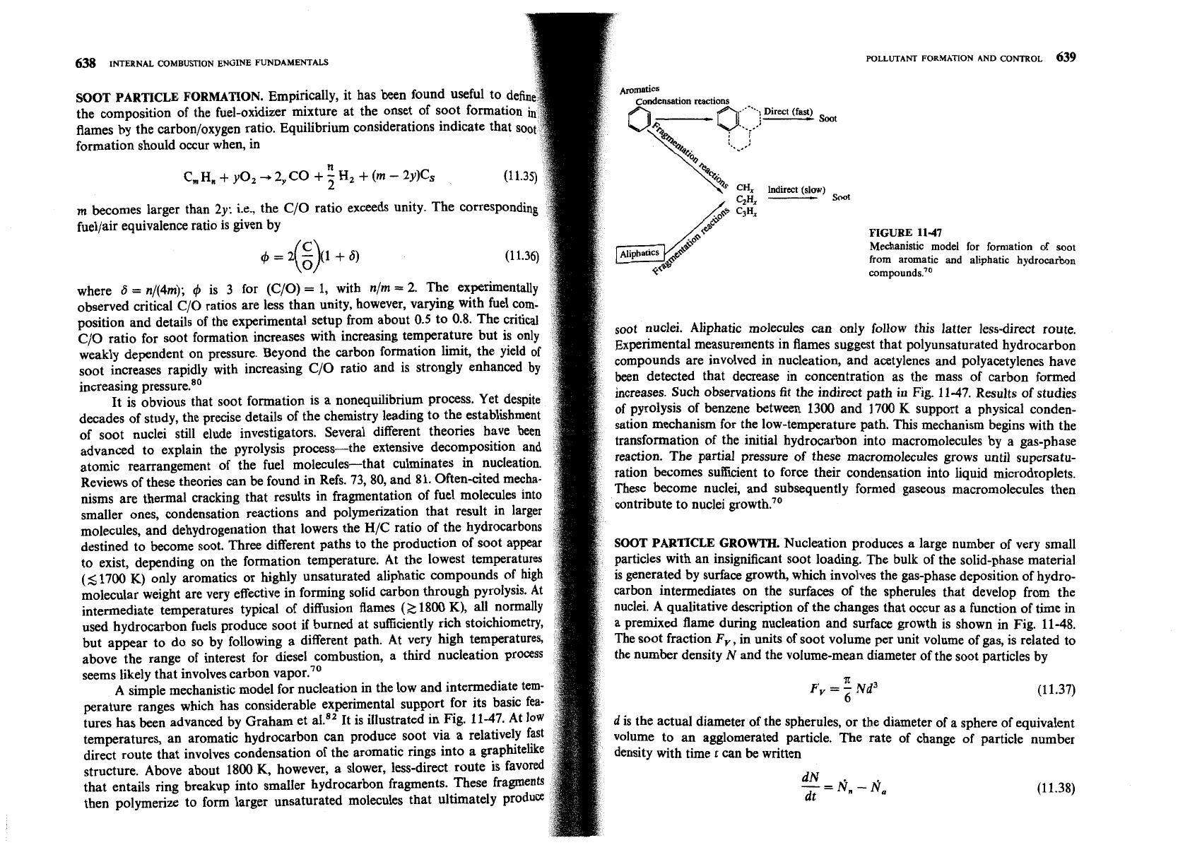
638
INTERNAL COMBUSTION ENGINE FUNDAMENTALS
SOOT PARTICLE FORMATION.
Empirically, it has been found useful to defi
the composition of the fuel-oxidizer mixture at the onset of soot formation
flames by the carbon/oxygen ratio. Equilibrium considerations indicate that so
formation should occur when, in
n
C, H,
+
yo,
-,
2,
CO
+
5
Hz
+
(m
-
2y)Cs
m
becomes larger than
2y:
i.e., the C/O ratio exceeds unity. The corresponding
fuellair equivalence ratio is given by
FIGURE
11-47
4=2
-
(i+6)
(3
Mechanistic model for formation of soot
from aromatic
and
aliphatic hydrocarbon
c~mpounds.'~
where
6
=
n/(4m);
4
is
3
for (C/O)
=
1, with n/m
=
2.
The experimentally
observed critical C/O ratios are less than unity, however, varying with fuel com-
position and details of the experimental setup from about 0.5 to
0.8. The critical
C/O ratio for soot formation increases with increasing temperature but is only
soot nuclei. Aliphatic molecules can only follow this latter less-direct route.
weakly dependent on pressure. Beyond the carbon formation limit, the yield of
~xperimental measurements in flames suggest that polyunsaturated hydrocarbon
soot increases rapidly with increasing C/O ratio and is strongly enhanced
by
compounds are involved in nucleation, and acetylenes and polyacetylenes have
increasing pre~sure.'~
been detected that decrease in concentration as the mass of carbon formed
It is obvious that soot formation is a nonequilibrium process. Yet despite
increases. Such observations fit the indirect path in Fig. 11-47. Results of studies
decades of study, the precise details of the chemistry leading to the establishment
of pyrolysis of benzene between 1300 and 1700
K
support a physical conden-
of soot nuclei still elude investigators. Several different theories have been
sation mechanism for the low-temperature path. This mechanism begins with the
advanced to explain the pyrolysis process-the extensive decomposition and
transformation of the initial hydrocarbon into macromolecules by a gas-phase
atomic rearrangement of the fuel molecules-that culminates in nucleation.
reaction. The partial pressure of these macromolecules grows until
supersatu-
Reviews of these theories can be found in Refs. 73,80, and 81.Often-cited mecha-
ration becomes sufficient to force their condensation into liquid micr~droplet~.
nisms are thermal cracking that results in fragmentation of fuel molecules into
ese become nuclei, and subsequently formed gaseous macromolecules then
smaller ones, condensation reactions and polymerization that result in larger
ntribute to nuclei growth.'O
molecules, and dehydrogenation that lowers the H/C ratio of the hydrocarbons
destined to become soot. Three different paths to the production of soot appear
SOOT PARTICLE GROWTH.
Nucleation produces a large number of very small
to exist, depending on the formation temperature. At the lowest temperatures
particles with an insignificant soot loading. The bulk of the solid-phase material
(5
1700 K) only aromatics or highly unsaturated aliphatic compounds of high
is
generated by surface growth, which involves the gas-phase deposition of hydro-
molecular weight are very effective in forming solid carbon through pyrolysis. At
carbon intermediates on the surfaces of the spherules that develop from the
intermediate temperatures typical of diffusion flames
(2
1800
K),
all normally
nuclei. A qualitative description of the changes that occur as a function of time in
used hydrocarbon fuels produce soot if burned at sufficiently rich stoichiomet
a premixed flame during nucleation and surface growth is shown in Fig. 11-48.
but appear to do so by following a different path. At very high temperature
The soot fraction
Fv, in units of soot volume per unit volume of gas, is related to
above the range of interest for diesel combustion, a third nucleation
proces
the number density
N
and the volume-mean diameter of the soot particles by
seems likely that involves carbon vapor.70
A simple mechanistic model for nucleation in the low and intermediate te
A
F
--Nd3
'-6
(11.37)
perature ranges which has considerable experimental support for its b
tures has been advanced by Graham et al." It is illustrated in Fig. 11-47. At
d
is the actual diameter of the spherules, or the diameter of a sphere of equivalent
temperatures, an aromatic hydrocarbon can produce soot via a relatively
v~hme to an agglomerated particle. The rate of change of particle number
direct route that involves condensation of the aromatic rings into
a
gra
density with time
t
can be written
structure. Above about 1800 K, however, a slower, less-direct route i
that entails ring breakup into smaller hydrocarbon fragments. These fr
-=N,-N,
dN
.
then polymerize to form larger unsaturated molecules that ultimate1
dt
(1
1.38)
INTERNAL COMBUSTION ENGINE FUNDAMENTALS
Time
-
POLLUTANT
FORMATION AND
CONTROL
641
ion and surface growth rates have diminished, the resulting particles resemble a
luster in which the original spherules retain much of their individual identity.
After surface growth essentially ceases, continued coalescence of the soot particles
results in the formation of chainlike structures of discrete spherules. This suggests
forces are significant. Positive charge measured on these particle
chains is claimed to be the cause of their chainlike
73
This latter
once surface growth ceases is termed aggregation.
It has been shown experimentally that during coagulation the rate of
decrease of particle number density was proportional to the product of a coagu-
lation coefficient and the square of the number density:
J
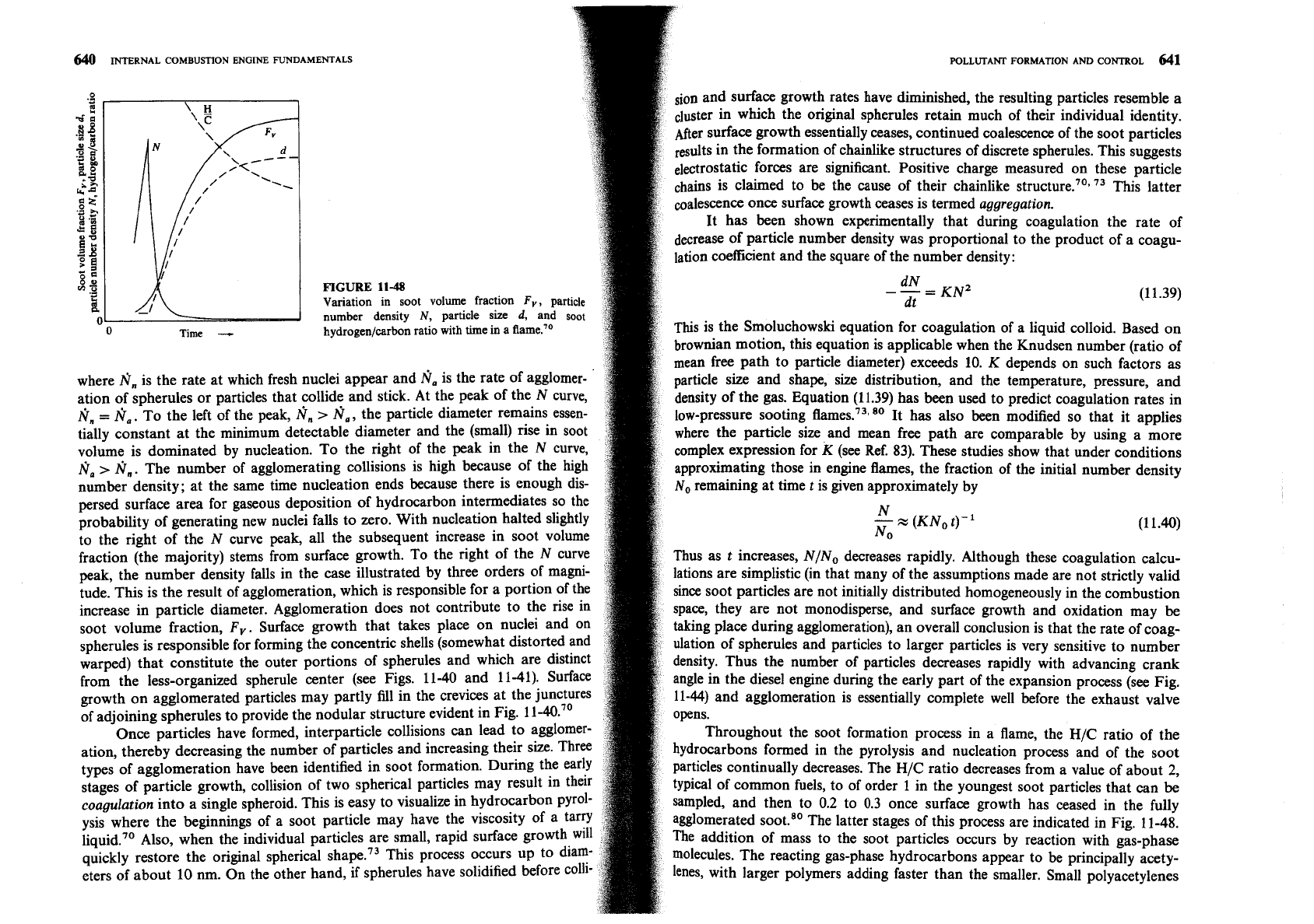
FIGURE
11-48
Variation in soot volume fraction
F,,
particle
dN
-
KNZ
dt
(11.39)
number density
N,
particle
size
d,
and
soot
hydrogen/carbon ratio with time in a flame.''
This is the Smoluchowski equation for coagulation of a liquid colloid. Based on
brownian motion, this equation is applicable when the Knudsen number (ratio of
mean free path to particle diameter) exceeds 10.
K
depends on such
fadors
as
where
N,
is the rate at which fresh nuclei appear and
fi,
is the rate of agglomer-
'
article
size and shape, size distribution, and the temperature, pressure, and
ation of spherules or particles that collide and stick. At the peak of the N curve,
density of the gas. Equation (11.39) has been used to predict coagulation rates in
Nn
=
N,.
To the left of the peak,
fin
>
N,,
the particle diameter remains essen-
lo~-preSSUre sooting fli~nes.~~~~~ It has also been modified so that it applies
tially constant at the minimum detectable diameter and the (small) rise in soot
where the particle size and mean free path are comparable by using a more
volume is dominated by nucleation. To the right of the peak in the N curve,
complex expression for K (see Ref. 83). These studies show that under conditions
fi,
>
N,.
The number of agglomerating collisions is high because of the high
approximating those in engine flames, the fraction of the initial number density
number density; at the same time nucleation ends because there is enough dis-
No remaining at time t is given approximately by
persed surface area for gaseous deposition of hydrocarbon intermediates so the
probability of generating new nuclei falls to zero. With nucleation halted slightly
N
-
x
(KN, t)-'
No
(1 1.40)
to the right of the N curve peak, all the subsequent increase in soot volume
fraction (the majority) stems from surface growth. To the right of the N curve
Thus as t increases, N/No decreases rapidly. Although these coagulation calcu-
peak, the number density falls in the case illustrated by three orders of magni-
lations are simplistic (in that many of the assumptions made are not strictly valid
tude. This is the result of agglomeration, which is responsible for a portion of the
since Soot particles are not initially distributed homogeneously in the combustion
increase in particle diameter. Agglomeration does not contribute to the rise in
space, they are not monodisperse, and surface growth and oxidation may
be
soot volume fraction,
F,.
Surface growth that takes place on nuclei and on
taking place during agglomeration), an overall conclusion is that the rate of coag-
spherules is responsible for forming the concentric shells (somewhat distorted and
ulation of spherules and particles to larger particles is very sensitive to number
warped) that constitute the outer portions of spherules and which are distinct
density. Thus the number of particles decreases rapidly with advancing crank
from the less-organized spherule center (see Figs. 11-40 and 11-41). Surface
angle in the diesel engine during the early part of the expansion process (see Fig.
growth on agglomerated particles may partly fill in the crevices at the junctures
11-44) and agglomeration is essentially complete well before the exhaust valve
of adjoining spherules to provide the nodular structure evident in Fig.
11-40.~'
opens.
Once particles have formed, interparticle collisions can lead to agglomer-
Throughout the soot formation process in a flame, the
H/C
ratio of the
ation, thereby decreasing the number of particles and increasing their size. Three
hydrocarbons formed in the pyrolysis and nucleation process and of the soot
types of agglomeration have been identified in soot formation. During the early
particles continually decreases. The
H/C
ratio decreases from a value of about
2,
stages of particle growth, collision of two spherical particles may result in their
typical of common fuels, to of order 1 in the youngest soot particles that can
be
coagulation into a single spheroid. This is easy to visualize in hydrocarbon p~rol-
sampled, and then to 0.2 to 0.3 once surface growth has ceased in the fully
ysis where the beginnings of a soot particle may have the viscosity of a tarry
agglomerated
The latter stages of this process are indicated in Fig. 11-48.
Also, when the individual particles are small, rapid surface growth will
The addition of mass to the soot particles occurs by reaction with gas-phase
quickly restore the original spherical shape.73 This process occurs up to dia*
molecules. The reacting gas-phase hydrocarbons appear to be principally acety-
eters of about 10 nm. On the other hand, if spherules have solidified before colli
len% with larger polymers adding faster than the smaller. Small polyacetylenes
642
MTERNAL
COMBUSTION ENGINE
FUNDAMENTALS
undergo further polymerization in the gas phase, presumably by the same mec
nism leading to nucleation. As a result of preferential addition of the larger po
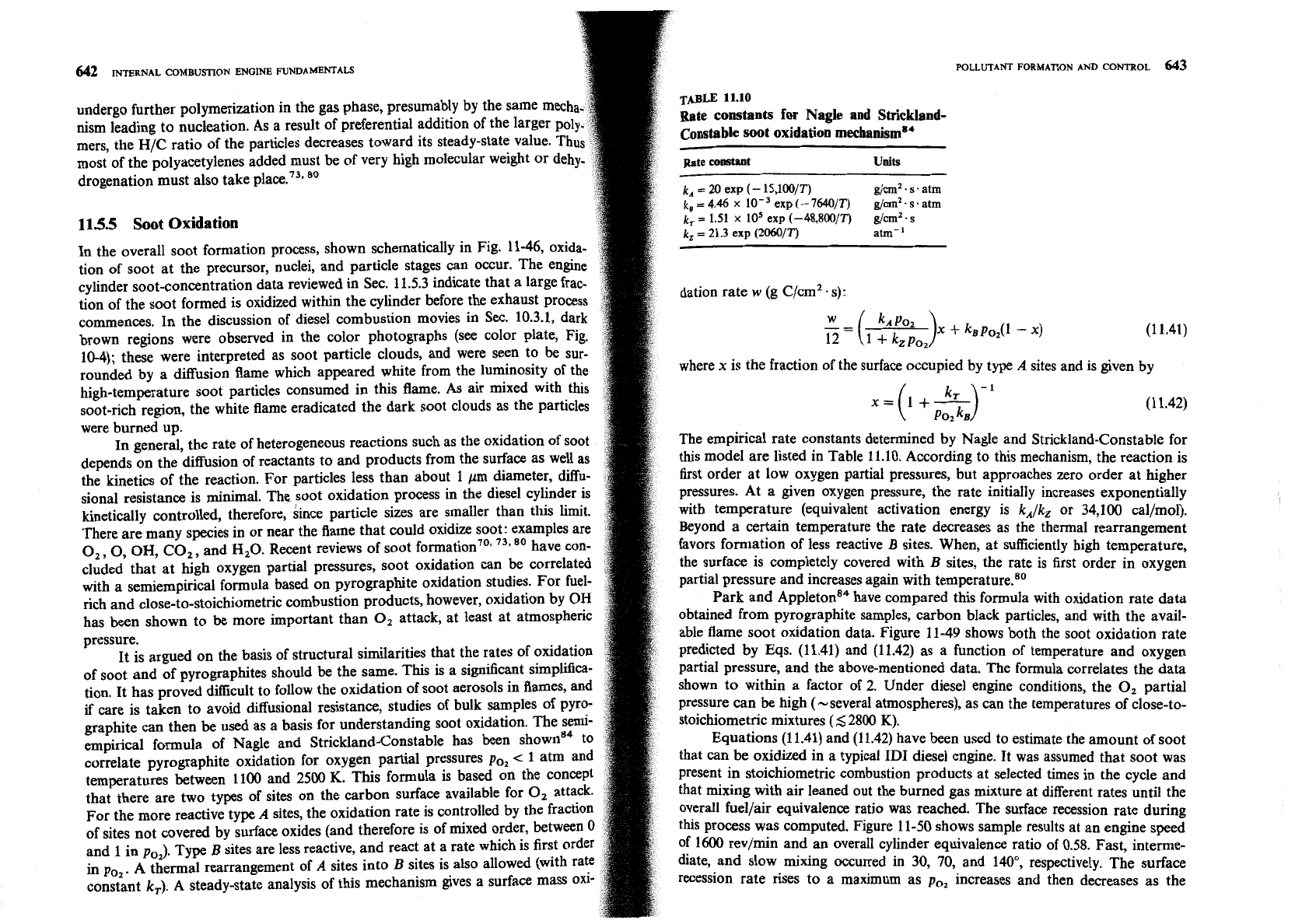
Rate constants for Nagle and Strickland-
mers, the H/C ratio of the particles decreases toward its steady-state value.
Constable soot oxidation mechanism84
most of the polyacetylenes added must be of very high molecular weight or
Rate
constant
Units
drogenation must also take place.73,
80
k,
=
20 exp
(-
15,10O/T)
g/cm2.
s
.
atm
k,
=
4.46
x
exp
(-
7640/T)
g/un2.
s
.
atm
115.5
Soot Oxidation
k,
=
1.51
x
lo5 exp (-48,800p)
gh2.
s
k,
=
21.3 exp (2060/T)
atm-'
In the overall soot formation process, shown schematically in Fig. 11-46, oxida-
tion of soot at the precursor, nuclei, and particle stages can occur. The engine
cylinder soot-concentration data reviewed in Sec. 11.5.3 indicate that a large
frat.
tion of the soot formed is oxidized within the cylinder before the exhaust process
dation rate
w
(g C/cmZ
.
s):
commences. In the discussion of diesel combustion movies in
Sec.
10.3.1, dark
brown regions were observed in the color photographs (see color plate, Fig.
=
(
k*p02 )x
+
kBpo,(l
-
x)
1
+
kz
PO,
(1 1.41)
10-4); these were interpreted as soot particle clouds, and were seen to be sur-
rounded by a diffusion flame which appeared white from the luminosity of the
where
x
is the fraction of the surface occupied by type
A
sites and is given by
high-temperature soot particles consumed in this flame. As air mixed with this
soot-rich region, the white flame eradicated the dark soot clouds as the particles
x= I+-
(
PoykJ1 (1 1.42)
were burned up.
In general, the rate of heterogeneous reactions such as the oxidation of soot
The empirical rate constants determined by Nagle and Strickland-Constable for
depends on the diffusion of reactants to and products from the surface as well as
this model are listed in Table 11.10. According to this mechanism, the reaction is
the kinetics of the reaction. For particles less than about 1
pm diameter, dfiu-
first order at low oxygen partial pressures, but approaches zero order at higher
sional resistance is minimal. The soot oxidation process in the diesel cylinder is
pressures. At a given oxygen pressure, the rate initially increases exponentially
kinetically controlled, therefore, since particle sizes are smaller than this limit.
with temperature (equivalent activation energy is
kA/kz or 34,100 cal/mol).
There are many species in or near the flame that could oxidize soot: examples are
Beyond a certain temperature the rate decreases as the thermal rearrangement
0,
,0, OH, CO,, and H,O. Recent reviews of soot
739
have con-
favors formation of less reactive
B
sites. When, at sufficiently high temperature,
cluded that at high oxygen partial pressures, soot oxidation can be correlated
the surface is completely covered with
B
sites, the rate is first order in oxygen
with a semiempirical formula based on pyrographite oxidation studies. For fuel-
partial pressure and increases again with
temperat~re.~~
rich and close-to-stoichiometric combustion products, however, oxidation by
OH
Park and
leton' on'^
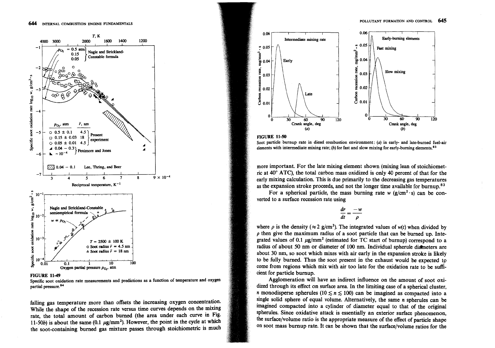
have compared this formula with oxidation rate data
has been shown to be more important than
0,
attack, at least at atmospheric
obtained from pyrographite samples, carbon black particles, and with the avail-
pressure.
able flame soot oxidation data. Figure 11-49 shows both the soot oxidation rate
It is argued on the basis of structural similarities that the rates of oxidation
predicted by Eqs. (11.41) and (11.42) as a function of temperature and oxygen
of soot and of pyrographites should be the same. This is a significant simplfica-
partial pressure, and the above-mentioned data. The formula correlates the data
tion. It has proved difficult to follow the oxidation of soot aerosols in flames, and
shown to within a factor of 2. Under diesel engine conditions, the
0,
partial
if
care is taken to avoid diffusional resistance, studies of bulk samples of pyro-
Pressure can be high (-several atmospheres), as can the temperatures of close-to-
graphite can then
be
used as a basis for understanding soot oxidation. The semi-
stoichiometric mixtures
(5
2800
K).
empirical formula of Nagle and Strickland-Constable has been shown84 to
Equations (1 1.41) and (1 1.42) have been used to estimate the amount of soot
correlate pyrographite oxidation for oxygen partial pressures PO,
<
1 atm and
that can
be
oxidized in a typical ID1 diesel engine. It was assumed that soot was
temperatures between 1100 and 2500
K.
This formula
is
based on the conce
Present in stoichiometric combustion products at selected times in the cycle and
that there are two types of sites on the carbon surface available for
0,
att
that mixing with air leaned out the burned gas mixture at different rates until the
For the more reactive type
A
sites, the oxidation rate is controlled by the frac
overall fuel/air equivalence ratio was reached. The surface recession rate during
of sites not covered by surface oxides (and therefore is of mixed order, between
this Process was computed. Figure 11-50 shows sample results at an engine speed
and 1 in p,,). Type
B
sites are less reactive, and react at a rate which is first orde
of 1600 rev/min and an overall cylinder equivalence ratio of 0.58. Fast, interme-
in po2. A thermal rearrangement of
A
sites into
B
sites is also allowed (with
diate, and slow mixing occurred in 30, 70, and 140", respectively. The surface
constant
k,).
A steady-state analysis of this mechanism gives a surface mass
recession rate rises to a maximum as po2 increases and then decreases as the
644
INTERNAL
COMBUSTION
ENGINE FUNDAMENTALS
T,
K
4000
3000
2000
1600
1400 1200
I I
II
I
1
I I
-
1
0.15
}
Nagle
and
Strickland-
Constable formula
I
0.04.
-
0.1
Lee,
Thring, and
Beer
-7
c
3
4
5
6
7
8
9
x
lo-4
Reciprocal
temperature,
K-'
Nagle
and
Strickland-Constable
-
T
=
2500
f
100
K
-
o
Soot
radius
?
=
4.5
nm
..
A
Soot
radius
f
=
18
nm
0.1 1 10 100
Oxygen
partial
pressure
pq,
aim
FIGURE
11-49
Specific soot oxidation rate measurements and predictions
as
a function of temperature and oxygen
partial pre~sure.'~
falling gas temperature more than offsets the increasing oxygen concentration.
While the shape of the recession rate versus time curves depends on the mixing
rate, the total amount of carbon burned (the area under each curve in Fig.
11-50b) is about the same (0.1 pg/mm2). However, the point in the cycle at which
the soot-containing burned gas mixture passes through stoichiometric is much
I I
I
Intermediate
mixing rate
Crank
angle, deg
(b)
FIGURE
11-50
Soot particle burnup rate in diesel combustion environment:
(a)
in early-
and
late-burned fuel-air
elements with intermediate mixing rate;
(b)
for fast and slow mixing for early-burning eleme~ts.~'
more important. For the late mixing element shown (mixing lean of stoichiomet-
ric
at 40" ATC), the total carbon mass oxidized is only
40
percent of that for the
early mixing calculation. This is due primarily to the decreasing gas temperatures
as the expansion stroke proceeds, and not the longer time available for
b~rnup.*~
For a spherical particle, the mass burning rate
w
(g/cm2.s) can be con-
verted to a surface recession rate using
where
p
is the density
(FZ
2
g/cm3). The integrated values of
w(t)
when divided by
p
then give the maximum radius of a soot particle that can be burned up. Inte-
grated values of 0.1 pg/mm2 (estimated for TC start of burnup) correspond to a
radius of about 50
nm
or diameter of 100
nrn.
Individual spherule diameters are
about 30 nm, so soot which mixes with air early in the expansion stroke is likely
to be fully burned.
Thus
the soot present in the exhaust would be expected tp
come from regions which mix with air too late for the oxidation rate to
be
suffi-
cient for particle burnup.
Agglomeration will have
an
indirect influence on the amount of soot oxi-
dized
through its effect on surface area. In the limiting case of a spherical cluster,
n
monodisperse spherules (10
5
n
5
100) can be imagined as compacted into a
single solid sphere of equal volume. Alternatively, the same
n
spherules can be
imagined compacted into a cylinder of diameter equal to that of the original
spherules. Since oxidative attack is essentially an exterior surface phenomenon,
the
surface/volume ratio is the appropriate measure of the effect of particle shape
on soot mass burnup rate. It can be shown that the surface/volume ratios for the
646
INTERNAL COMBUSTION
ENGINE
FUNDAMENTALS
single sphere, cylinder, and individual spherule are in the ratio
n-'I3,
3,
and
respectively. Thus agglomeration will decrease the relative oxidation rate. In th
limit spherical clusters are less desirable than a chain; the larger the cluster th
bigger the relative reduction in surface area. However, the densely packed spher
ule limit does not appear to
be
approached in practice. A specific surface area, of
about 200 m2/g for diesel soot, has been mea~ured.'~ A smooth-surfaced 30-nm
diameter spherule with a 2-g/cm3 density has a surface/mass ratio of 100 m2Ig;
the measured value is about twice this value, indicating low porosity and an
agglomerate structure which is loosely rather than densely packed.83
Equation (11.41) shows a maximum recession rate in combustion products
corresponding to a fuellair equivalence ratio of about
0.9.
Recent evidence shows
that in an atmospheric pressure environment with rich and close-to.
stoichiometric combustion products where
0,
mole fractions are low, oxidation
by OH radical attack is much more significant than oxidation by
0
or
0,.
The
OH radical may be important in oxidizing soot in the flame zone under close-to.
stoichiometric conditions.
115.6
Adsorption and Condensation
The final process in the particulate formation sequence illustrated in Fig. 11-46 is
adsorption and condensation of hydrocarbons. This occurs primarily after the
cylinder gases have been exhausted from the engine, as these exhaust gases are
diluted with air. In the standard particulate mass emission measurement process
this occurs in a dilution tunnel which simulates approximately the actual atmo-
spheric dilution process.
A
diluted exhaust gas sample is filtered to remove the
particulate. After equilibrating the collection filter at controlled conditions to
remove water vapor, the particulate mass is obtained by weighing. In the pre-
scribed EPA procedure, the Alter temperature must not exceed 52•‹C. For a given
exhaust gas temperature, the filter (and sample) temperature depends on the dilu-
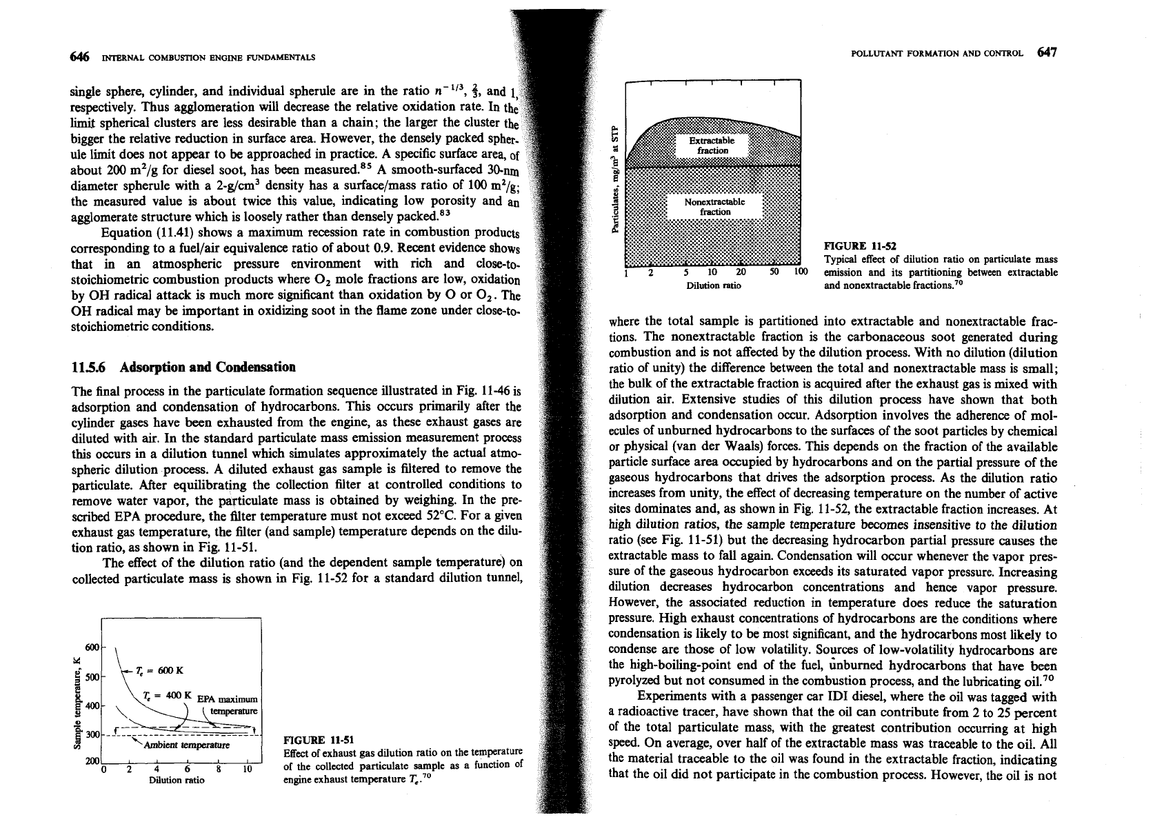
tion ratio, as shown in Fig. 11-51.
The effect of the dilution ratio (and the dependent sample temperature) on
collected particulate mass is shown in Fig. 11-52 for a standard dilution tunnel,
mJ
0246810
Dilution ratio
FIGURE
11-51
Effect of exhaust
gas
dilution ratio on the temperature
of the collected particulate sample as a function of
engine exhaust temperature T,."
FIGURE
11-52
Typical effect of dilution ratio
emission and its partitioning
on particulate
mass
between extractable
Dilution ratio and nonextractable fractions.'O
where the total sample is partitioned into extractable and nonextractable frac-
tions. The nonextractable fraction is the carbonaceous soot generated during
combustion and is not affected by the dilution process. With no dilution (dilution
ratio of unity) the difference between the total and nonextractable mass is small;
the bulk of the extractable fraction
is
acquired after the exhaust gas is mixed with
dilution air. Extensive studies of this dilution process have shown that both
adsorption and condensation occur. Adsorption involves the adherence of mol-
ecules of unburned hydrocarbons to the surfaces of the soot particles by chemical
or physical (van der Waals) forces. This depends on the fraction of the available
particle surface area occupied by hydrocarbons and on the partial pressure of the
gaseous hydrocarbons that drives the adsorption process. As the dilution ratio
increases from unity, the effect of decreasing temperature on the number of active
sites dominates and, as shown in Fig. 11-52, the extractable fraction increases. At
high dilution ratios, the sample temperature becomes insensitive to the dilution
ratio (see Fig. 11-51) but the decreasing hydrocarbon partial pressure causes the
extractable mass to fall again. Condensation will occur whenever the vapor pres-
sure of the gaseous hydrocarbon exceeds its saturated vapor pressure. Increasing
dilution decreases hydrocarbon concentrations and hence vapor pressure.
However, the associated reduction in temperature does reduce the saturation
pressure. High exhaust concentrations of hydrocarbons are the conditions where
condensation is likely to be most significant, and the hydrocarbons most likely to
condense are those of low volatility. Sources of low-volatility hydrocarbons are
the high-boiling-point end of the fuel,
&burned hydrocarbons that have been
pyrolyzed but not consumed in the combustion process, and the lubricating oil."
Experiments with a passenger car ID1 diesel, where the oil was tagged with
a radioactive tracer, have shown that the oil can contribute from 2 to 25 percent
of the total particulate mass, with the greatest contribution occurring at high
speed. On average, over half of the extractable mass was traceable to the oil. All
the material traceable to the oil was found in the extractable fraction, indicating
that the oil did not participate in the combustion process. However, the oil is not
POLLUTANT FORMATION AND
(
always a significant contributer: in another engine,
of extractable material.'O*
"
11.6
EXHAUST
GAS
TREATMENT
fuel
was the dominant soul
11.6.1 Available Options
Our discussion so far has focused on
engine
emissions. Further reductions
in
emissions can be obtained by removing pollutants from the exhaust gases in the
engine exhaust system. Devices developed to achieve this result include catalytic
converters (oxidizing catalysts for HC and CO, reducing catalysts for NO,, and
three-way catalysts for all three pollutants), thermal reactors (for HC and CO),
and traps or filters for particulates.
The temperature of exhaust gas in a spark-ignition engine can vary from
300 to 400OC during idle to about 900•‹C at high-power operation. The most
common range is
400
to 6WC. Spark-ignition engines usually operate at fuellair
equivalence ratios between about 0.9 and 1.2 (see Sec. 7.1). The exhaust gas may
therefore contain modest amounts of oxygen (when lean) or more substantial
amounts of CO (when rich). In contrast, diesel engines, where load is controlled
by the amount of fuel injected, always operate lean. The exhaust gas therefore
contains substantial oxygen and is at a lower temperature (200 to 500•‹C).
Removal of gaseous pollutants from the exhaust gases after they leave the engine
cylinder can be either thermal or catalytic. In order to oxidize the hydrocarbons
in the gas phase without a catalyst, a residence time of order or greater than
50 ms and temperatures in excess of 600•‹C are required. To oxidize CO, tem-
peratures in excess of 700•‹C are required. Temperatures high enough for some
homogeneous thermal oxidation can
be
obtained by spark retard (with some loss
in efficiency) and insulation of the exhaust ports and manifold. The residence
time can be increased by increasing the exhaust manifold volume to form a
thermal reactor
(see
Sec.
11.6.3). However, this approach has limited application.
Catalytic oxidation of CO and hydrocarbons in the exhaust can be
achieved at temperatures as low as 250•‹C. Thus effective removal of these pol-
lutants occurs over a much wider range of exhaust temperatures than can be
achieved with thermal oxidation. The only satisfactory method known for the
removal of NO from exhaust gas involves catalytic processes. Removal of NO
by
catalytic oxidation to NO, requires temperatures <400"C (from equilibrium
considerations) and subsequent removal of the NO, produced. Catalytic reaction
of NO with added ammonia
NH,
is not practical because of the transient varia-
tions in NO produced in the engine. Reduction of NO by CO, hydrocarbons, or
H,
in the exhaust to produce N2 is the preferred catalytic process. It is only
feasible in spark-ignition engine exhausts. Use of catalysts in spark-ignition
engines for CO, HC, and NO removal has become widespread. Catalysts are
discussed in
Sec. 11.6.2.
Particulates in the exhaust gas stream can be removed by a trap. Due to the
small particle size involved, some type of filter is the most effective trapping
method. The accumulation of mass within the trap and the increase in exhaust
manifold pressure during trap operation are major development problems. Diesel
particulates, once trapped, can be burned up either by initiating oxidation within
the trap with an external heat source or by using a trap which contains cata-
lytically active material. The operation of particulate traps is reviewed briefly in
Sec. 11.6.4.
11.6.2 Catalytic Converters
The catalytic converters used in spark-ignition engines consist of an active cata-
lytic material in a specially designed metal casing which directs the exhaust gas
flow through the catalyst bed. The active material employed for CO and
HC
oxidation or NO reduction (normally noble metals, though base metals oxides
can be used) must be distributed over a large surface area so that the mass-
transfer characteristics between the gas phase and the active catalyst surface are
sufficient to allow close to
100 percent conversion with high catalytic activity.
The two configurations commonly used are shown in Fig. 11-53. One system
employs a ceramic honeycomb structure or monolith held in a metal can in the
exhaust stream. The active (noble metal) catalyst material is impregnated into a
highly porous alumina
washcoat about 20 pm thick that is applied to the pas-
sageway walls. The typical monolith has square-cross-section passageways with
inside dimensions of
-
1 mm separated by thin (0.15 to 0.3
mm)
porous walls.
The number of passageways per square centimeter varies between about 30 and
60.
The washcoat, 5 to 15 percent of the weight of the monolith, has a surface
area of 100 to 200 m2/g. The other converter design uses a bed of spherical
ceramic pellets to provide a large surface area in contact with the flow. With
pellet catalysts, the noble metal catalyst is impregnated into the highly porous
surface of the spherical alumina pellets (typically 3 mm diameter) to a depth of
about 250
pm. The pellet material is chosen to have good crush and abrasion
resistance after exposure to temperatures of order
1000•‹C. The gas flow is
directed down through the bed as shown to provide a large flow area and low
pressure drop. The gas flow is turbulent which results in high mass-transfer rates;
in the monolith catalyst passageways, it is laminar.
OXIDATION
CATALYSTS.
The function of an oxidation catalyst is to oxidize CO
and hydrocarbons to CO, and water in an exhaust gas stream which typically
contains
-
12 percent CO, and H,O, 100 to 2000 ppm NO, -20 ppm SO,, 1 to
5
percent 02, 0.2 to 5 percent CO, and 1000 to
6000
ppm C, HC, often with
small amounts of lead and phosphorus. About half the hydrocarbons emitted by
the SI engine are unburned fuel compounds. The saturated hydrocarbons (which
comprise some 20 to 30 percent) are the most difficult to oxidize. The ease of
oxidation increases with increasing molecular weight. Sufficient oxygen must be
present to oxidize the CO and HC. This may be supplied by the engine itself
