Heywood J.B. Internal Combustion Engines Fundamentals
Подождите немного. Документ загружается.

670
INTERNAL
COMBU~ON
ENGME
FUNDAMENTALS
the walls of the intake system, combustion chamber, and exhaust system, and
the coolant is of obvious importance to the engine designer.
122 MODES OF HEAT TRANSFER
The following modes of heat transfer are important.
12.2.1 Conduction
Heat is transferred by molecular motion, through solids and through fluids at
rest, due to a temperature gradient. The heat transfer by conduction, per unit
area per unit time, q, in a steady situation is given by Fourier's law:
4-
-kVT
where
k
is the thermal conductivity. For a steady one-dimensional temperature
variation
8
d~
q,=-=
-k-
A
dx
Heat is transferred by conduction through the cylinder head, cylinder walls, and
piston; through the piston rings to the cylinder wall; through the engine block
and manifolds.
122.2 Convection
Heat is transferred through fluids in motion and between a fluid and solid su
in relative motion. When the motion is produced by forces other than gravity, th
term forced convection is used. In engines the fluid motions are turbulent
(
Chap. 8).
Heat is transferred by forced convection between the in-cylinder gases an
the cylinder head, valves, cylinder walls, and piston during induction, compres
sion, expansion, and exhaust processes. Heat is transferred by forced convectio
from the cylinder walls and head to the coolant (which may
be
liquid or gas),
an
from the piston to the lubricant or other piston coolant. Substantial convectiv
heat transfer occurs to the exhaust valve, exhaust port, and exhaust manifol
during the exhaust process. Heat transfer by convection in the inlet system
used to raise the temperature of the incoming charge. Heat is also
transferr
from the engine to the environment by convection.
In steady-flow forced-convection heat-transfer problems, the heat flux
transferred to
a
solid surface at temperature
T,
from a flowing fluid stream
temperature
T
is determined from the relation
q
=
h,(T
-
T,)
where
hc
is called the heat-transfer coefficient. For many flow geometries (such as
flow through pipes or over a plate),
h,
is given by relations of the form
("1")'(E$y
(y)
=
constant
x
-
where
L
and
v
are a characteristic length and velocity. The terms in brackets
from left to right are the Nusselt, Reynolds, and Prandtl dimensionless numbers,
respectively. For gases, the Prandtl number (c,p/k) varies little and is about 0.7
(see
Sec. 4.8).
When boiling occurs at the surface (i.e., vapor is formed in the liquid), as
may be the case in high heat flux areas on the coolant side in water-cooled
engines, then different relationships for
h,
must be used.
12.23 Radiation
Heat exchange by radiation occurs through the emission and absorption of elec-
tromagnetic waves. The wavelengths at which energy is transformed into thermal
energy are the visible range (0.4 to 0.7 pm) and the infrared (0.7 to 40 pm). Heat
transfer by radiation occurs from the high-temperature combustion gases and the
flame region to the combustion chamber walls (although the magnitude of this
radiation heat transfer relative to convective heat transfer
is
only significant in
diesel engines). Heat transfer by radiation to the environment occurs from all the
hot external surfaces of the engine.
The theory of radiant heat transfer starts from the concept of a "black
body,"
i.e., a body that has a surface that emits or absorbs equally well radiation
of all wavelengths and that reflects none of the radiation falling on it. The heat
flux from one plane black body at temperature
T,
to another at temperature T2
parallel to it across a space containing no absorbing material is given by
where
a
is the Stefan-Boltzmann constant
5.67
x
lo-'
W/m2
.K4.
Real surfaces
are not "black" but reflect radiation to an extent which depends on wavelength.
Gases are far from this black-body idealization. They absorb and emit radiation
almost exclusively within certain wavelength bands characteristic of each species.
These departures from black-body behavior are usually dealt with by applying a
multiplying factor (an
emissivity,
E)
to Eq. (12.4). Similarly, a "shape factor" is
applied to account for the fact that the angle of incidence of the radiation usually
varies over any actual surface. These factors can be calculated for simple cases.
12.2.4 Overall Heat-Transfer Process
Figure 12-1 shows, schematically, the overall heat-transfer process from the gases
within the cylinder through the combustion chamber wall to the coolant flow.
The heat flux into the wall has in general both a convective and a radiation
component. The heat flux is conducted through the wall and then convected from
672
INTERNAL COMBUSTION
ENGINE
FUNDAMENTALS
ENGINE
HEAT
TRANSFER
673
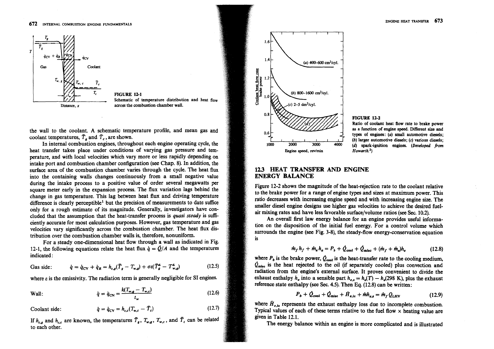
FIGURE
Schematic
121
of temperature distribution
and heat
flc
Distance,
x
across the combustion chamber
wall.
the wall to the coolant.
A
schematic temperature profile, and mean gas and
coolant temperatures,
Fa
and
Tc,
are shown.
In internal combustion engines, throughout each engine operating cycle, the
heat transfer takes place under conditions of varying gas pressure and tem-
perature, and with local velocities which vary more or less rapidly depending on
intake port and combustion chamber configuration (see Chap. 8). In addition, the
surface area of the combustion chamber varies through the cycle. The heat
flux
into the containing walls changes continuously from a small negative value
during the intake process to a positive value of order several megawatts per
square meter early in the expansion process. The flux variation lags behind the
change in gas temperature. This lag between heat flux and driving temperature
difference is clearly perceptible1 but the precision of measurements to date suffice
only for a rough estimate of its magnitude. Generally, investigators have con-
cluded that the assumption that the heat-transfer process is
quasi
steady
is sufi-
ciently accurate for most calculation purposes. However, gas temperature and gas
velocities vary significantly across the combustion chamber. The heat flux dis-
tribution over the combustion chamber walls is, therefore,
nonuniform.
For a steady one-dimensional heat flow through a wall as indicated in Fig.
12-1, the following equations relate the heat flux
q
=
&A
and the temperatures
indicated
:
where
E
is the emissivity. The radiation term is generally negligible for SI engines.
Wall:
Coolant side
:
4
=
9cv
=
hC,,(Tw,
-
Tc)
(12.7)
If he, and
h,,
are known, the temperatures re, TW,#, Tw,c, and
Fc
can
be
related
to each other.
FIGURE
122
Ratio of coolant heat flow rate to brake power
as
a function of engine
speed.
Diffemt
size
and
types of engines:
(a)
small
automotive diesels;
(b)
larger automotive diesels;
(c)
various diesels;
(a)
spark-ignition engines.
(Developed
from
.
-
-
-
Euginc
speed,
dmin
Howmth.')
123
HEAT TRANSFER AND ENGINE
ENERGY
BALANCE
Figure 12-2 shows the magnitude of the heat-rejection rate to the coolant relative
to the brake power for a range of engine types and sizes at maximum power. This
ratio decreases with increasing engine speed and with increasing engine size. The
smaller diesel engine designs use higher gas velocities to achieve the desired
fuel-
air
mixing rates and have less favorable surface/volume ratios (see Sec. 10.2).
An overall first law energy balance for an engine provides useful informa-
tion on the disposition of the initial fuel energy. For a control volume which
surrounds the engine
(see
Fig. 3-8), the steady-flow energy-conservation equation
is
where
P,
is the brake power,
e,,
is the heat-transfer rate to the cooling medium,
&,,
is the heat rejected to the oil
(if
separately cooled) plus convection and
radiation from the engine's external surface. It proves convenient to divide the
exhaust enthalpy he into a sensible part
he,,
=
hdT)
-
hd298
K),
plus the exhaust
reference state enthalpy
(see
Sec.
4.5).
Then
Eq.
(12.8) can be written:
where
fie,ic
represents the exhaust enthalpy loss due to incomplete combustion.
Typical values of each of these terms relative to the fuel flow
x
heating value are
given in Table 12.1.
The energy balance within an engine is more complicated and is illustrated
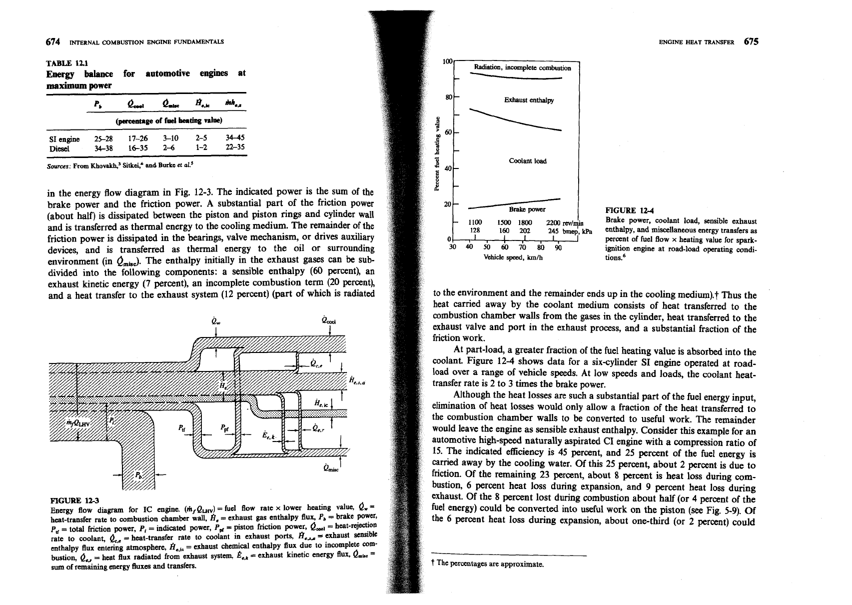
TABLE
121
Energy balance for automotive engines at
maximum power
P,
&
Q-
H..k
"'4,
(Pereenupe
of fd
beating
vdw)
SI engine
25-28
17-26
3-10
2-5
34-45
Diesel
34-38 16-35 26 1-2 22-35
Sowces:
From
Khovakh,'
Sitkei,*
and
Burke
et
al?
in the energy flow diagram in Fig. 12-3. The indicated power is the sum of the
brake power and the friction power.
A
substantial part of the friction power
(about half) is dissipated between the piston and piston rings and cylinder wall
and is transferred
as
thermal energy to the cooling medium. The remainder of the
friction power is dissipated in the bearings, valve mechanism, or drives auxiliary
devices, and is transferred as thermal energy to the oil or surrounding
environment (in
&,,,,).
The enthalpy initially in the exhaust gases can
be
sub-
divided into the following components: a sensible enthalpy
(60
percent), an
exhaust kinetic energy
(7
percent), an incomplete combustion term (20 percent),
and a heat transfer to the exhaust system (12 percent) (part of which is radiated
FIGURE
123
Energy flow diagram for
IC
engine.
(rir/Q,)
=
fuel Bow rate
x
lower heating value,
Q,
=
heat-transfer
rate
to combustion chamber wall,
8,
=
exhaust gas enthalpy flux,
P,
=
brake power,
P,
=
total friction power,
P,
=
indicated power,
P,,
=
piston friction power,
e,,
=
heat-rejection
rate to coolant,
&,
=
heat-transfer rate to coolant in exhaust ports, k,,, =exhaust sensible
enthalpy flux entering atmosphere,
k,,
=exhaust chemical enthalpy flux due to incomplete
corn-
bustion,
&,
=
heat flux radiated from exhaust system,
&+,
=
exhaust kinetic energy flux,
&i,
=
sum of remaining energy fluxea and transfers.
Radiation,
incomplete
combustion
--
Exhaust
enthalpy
Coolant
load
FIGURE
124
-
1100
1500
1800
2200
mlmia
Brake power, coolant load, sensible exhaust
128
160
2~
245
h,$,
enthalpy, and miscellaneous energy transfers as
I
percent of fuel flow
x
heating value for spark-
ignition engine at road-load operating condi-
Vehicle
speed,
kmlh
ti on^.^
to the environment and the remainder ends up in the cooling medium).? Thus the
heat carried away by the coolant medium consists of heat transferred to the
combustion chamber walls from the gases in the cylinder, heat transferred to the
exhaust valve and port in the exhaust process, and a substantial fraction of the
At part-load, a greater fraction of the fuel heating value is absorbed into the
coolant. Figure 12-4 shows data for a six-cylinder
SI
engine operated at road-
load over a range of vehicle speeds. At low speeds and loads, the coolant heat-
transfer rate is 2 to
3
times the brake power.
Although the heat losses are such a substantial part of the fuel energy input,
elimination of heat losses would only allow a fraction of the heat transferred to
the combustion chamber walls to be converted to useful work. The remainder
would leave the engine as sensible exhaust enthalpy. Consider this example for an
automotive high-speed naturally aspirated
CI
engine with a compression ratio of
15. The indicated efficiency is 45 percent, and 25 percent of the fuel energy is
camed away by the cooling water. Of this 25 percent, about
2
percent is due to
friction. Of the remaining 23 percent, about
8
percent is heat loss during com-
bustion,
6
percent heat loss during expansion, and
9
percent heat loss during
exhaust.
Of
the
8
percent lost during combustion about half (or 4 percent of the
fuel energy) could
be
converted into useful work on the piston
(see
Fig.
5-9).
Of
the
6
percent heat loss during expansion, about one-third (or 2 percent) could
t
The
percentages are approximate.
678
INTERNAL
COMBUSTION ENGINE FUNDAMENTALS
average effective gas temperature
T,,
such that
over
no
E
heat
the
keat
-tral
engi
was
nsfer
,ne cy
remo
data
cle.
lved
vlc
J
T,,
is the temperature at which the
from outside.
T,,
was obtained by
~tted versus gas-side combustion
(
wall woi
extrapol
:hamber
Jld
ati
SU
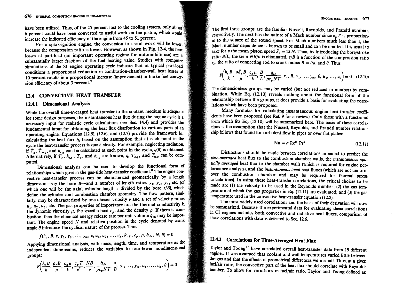
~erature back to the-zero heat-transfer axis. The Nusselt number, dehed as
plotted against Reynolds number, dehed as
where
m
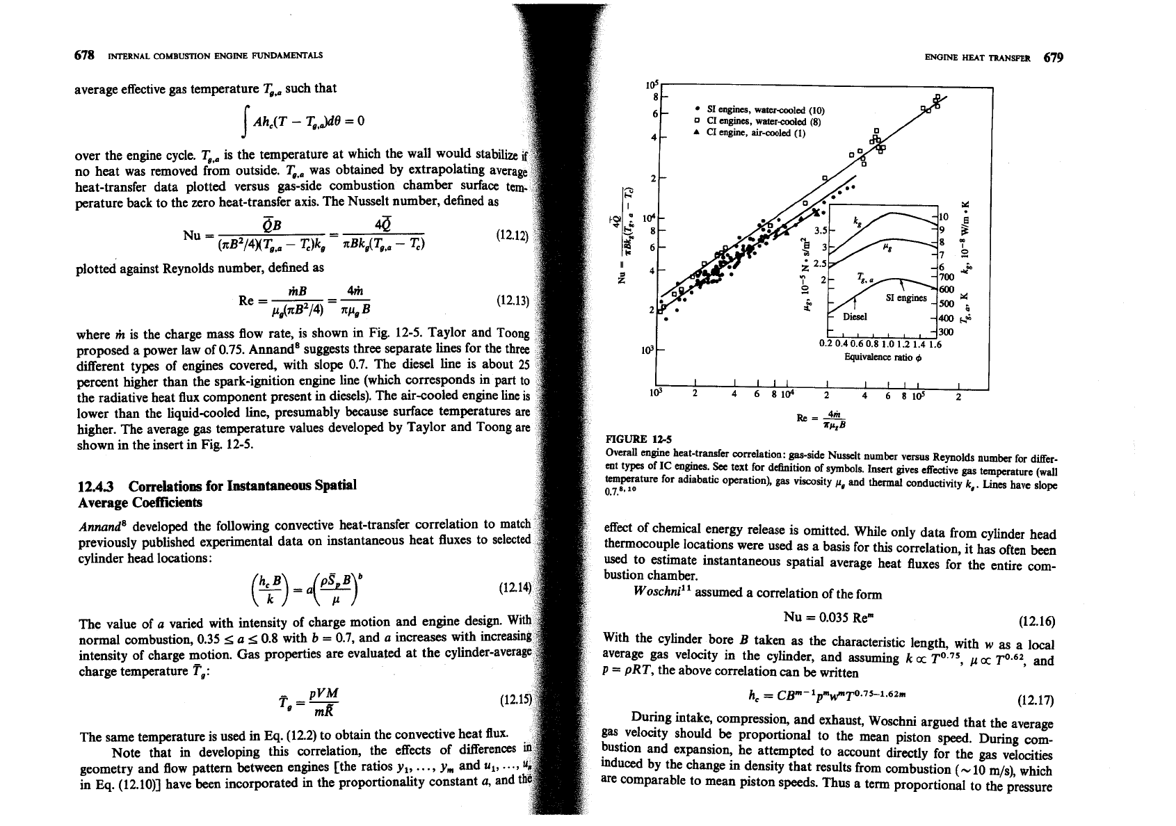
is the charge mass flow rate, is shown in Fig. 12-5. Taylor and Toong
proposed a power law of 0.75. Annand8 suggests three separate lines for the three
different types of engines covered, with slope 0.7. The diesel line is about
25
percent higher than the spark-ignition engine line (which corresponds in part to
the radiative heat flux component present in diesels). The air-cooled engine
lower than the
liquid-cooled line, presumably because surface temperatures
are
higher. The average gas temperature values developed by Taylor and Toong are
shown in the insert in Fig. 12-5.
12.43
Correlations
for
Instantaneous Spatial
Average Coefficients
Annands developed the following convective heat-transfer correlation to match
previously published experimental data on instantaneous heat fluxes to selected
cvlinder head locations:
The value of
a
varied with intensity of charge motion and engine design.
With
normal combustion, 0.35
<
a
<
0.8 with
b
=
0.7, and
a
increases with increasing
intensity of charge motion. Gas properties are evaluated at the cylinder-average
charge temperature
T,:
The same temperature is used in
Eq.
(12.2) to obtain the convective heat flux.
Note that in developing this correlation, the effects of differences
in
geometry and flow pattern between engines [the ratios y,,
..
.,
ym and u,,
...,
4,
in
Eq.
(12.10)] have been incorporated in the proportionality constant
a,
and
the
SI
engines, water-coo1ed (10)
D
CI
engines, water-cooled (8)
A
CI
engine, air-cooled
(1)
lV
r
Equivalence ratio
+
I
4th
Re
=
-
~PZB
FIGURE
124
Overall engine heat-transfer correlation: gas-side Nusselt number versus Reynolds number for
differ-
ent types of
IC
engines.
See
text for dehition of symbols. Insert gives effective gas temperature (wall
temperature for adiabatic operation),
gas
viscosity
p*
and thermal conductivity
k,.
Lines
have slope
0.7.8.
lo
effect of chemical energy release is omitted. While only data from cylinder head
thermocouple locations were used as a basis for this correlation, it has often been
used to estimate instantaneous spatial average heat fluxes for the entire com-
bustion chamber.
Woschni" assumed a correlation of the form
cylinder bore
B
taken as the characteristic length, with
w
as a local
average gas velocity in the cylinder, and assuming
k
cc
p
cc
and
p
=
pRT,
the above correlation can
be
written
During intake, compression, and exhaust, Woschni argued that the average
gas velocity should
be
proportional to the mean piston speed. During com-
L.....
~d expansion, he attempted to account directly for the gas velocities
r
the change in density that results from combustion
(-
10 m/s), which
rable to mean piston speeds. Thus a term proportional to the pressure
ENGINE
HEAT
TRANSFER
681
680
INTERNAL
COMBUSTTON
ENGINE
FUNDAMENTALS
lations for Instantaneous
Local
rise due to combustion
(p
-
p,,,) was added
(p,
is the motored cylinder pressure).
The coefficients relating the local average gas velocity
w
to the mean piston speed
and
(p
-
pJ were determined by fitting the correlation, integrated over the ~eFeuvre
et
a1.lS and Dent and Sulaimant6 have proposed the use of the flat-
engine cycle, to time-averaged measurements of heat transfer to the coolant for a plate forced convection heat-transfer correlation formula
wide range of engine operating conditions for a direct-injection four-valve diesel
without swirl.
T
in Eq. (12.17) is the mean cylinder gas temperature defined by
(
y)
=
0.036($)0'8(7r'333
(12.20)
Eq. (12.15); the same temperature is used to obtain the heat flux from the heat-
transfer coefficient
h,.
Thus this correlation represents spatially averaged
corn-
where
1
is the length of the plate and
v
the flow velocity over the plate. This
bustion chamber heat fluxes.
n applied to
DI
diesel engines with swirl, with
1
and
u
evaluated
The average cylinder gas velocity
w
(meters per second) determined for a
four-stroke, water-cooled, four-valve direct-injection
CI
engine without swirl
was
1
=
2sr
u
=
rw
expressed as follows
:
[
GT,
o
being the solid-body angular velocity of the charge. The heat flux at any radius
w=
Cl~p+C2-@-p~]
r (with Pr
=
0.73) is then given by
Pr
K
k
wr2 0.8
where
V,
is the displaced volume, p is the instantaneous cylinder pressure, pr,
K,
@(r)
=
0.023
-
(-;-)
[Fa(r)
-
Tw(r)]
r
(12.21)
T,
are the working-fluid pressure, volume, and temperature at some reference
state (say inlet valve closing or start of combustion), and p, is the motored
This equation can
be
used if the swirl variation with crank angle is known (see
cylinder pressure at the same crank angle as p.
Sec.
8.3) and an appropriate local gas temperature can be determined. It would
For the gas exchange period:
Cl
=
6.18,
C2
=
0
not
be
consistent to use the cylinder average gas temperature given by Eq. (12.15)
For the compression period
:
Cl
=
2.28,
C2
=
0
because during combustion substantial temperature nonuniformities exist
For the combustion and expansion period:
C1
=
2.28,
C2
=
3.24
x
between burned gases and air or mixture which has yet to bum or mix with
already burned gas.
Subsequent studies in higher-speed engines with swirl indicated higher heat
An alternative approach is zonal modeling, where the combustion
chamber
transfer than these velocities predicted. For engines with swirl, cylinder averaged
is divided into a relatively
small
number of zones each with its own temperature,
gas velocities were given by Eq. (12.18) with:
heat-transfer coefficient, and heat-transfer surface area history. This approach has
been applied to spark-ignition engines (e.g., Ref. 17), where the division of the
For the gas exchange period
:
c
=
6.18
+
0.41 7
2
s~
in-cylinder gases during combustion into a higher-temperature burned gas region
behind the flame and lower-temperature unburned gas region ahead of the flame
For the rest of cycle:
Ct
=
2.28
+
0.308
2
SP
is clear (see Fig. 9-4). The heat transfer to the combustion chamber surfaces in
contact with the unburned and burned gas zones [analagous to Eq.
(12.211 is
where
0,
=
Bod2 and w, is the rotation speed of the paddle wheel used to
measure the swirl velocity (see Sec. 8.3.1).12 Spark-ignition engine tests showed
that the above velocities gave acceptable predictions for this type of engine
0.
=
An,,
h~,
~(x
-
Tw)
0,
=
A,,
h,
b(G
-
T,)
(12.21u,b)
also.13
respectively. Since
h,
depends on local gas properties and velocities,
h,
. and
h,
Woschni's correlation, with the exponent in Eq. (12.17) equal to 0.8, can be
are not necessarily the same. Examples of how the burned gas wetted areas on
summarized as
:
the piston, cylinder head, and liner vary during the combustion process are given
h,(wIm2
.
K)
=
3.26~(m)-~.~~(k~a)~.~~(~)-~.~~w(m/~)~'~
(12.19)
in Fig. 14.8. Since the burned gas temperature
&
is much larger than the
burned
gas temperature, the heat flux from the burned gas zone dominates.
with
w
defined above.
One useful development of this two-zone approach is the division of the
~~h~~be~~~~ examined Woschni's formula and made changes to give better
burned gas zone into an adiabatic core and a thermal boundary layer. The
predictions of time-averaged heat fluxes measured with probes in a direct-
advantages are: (1) this corresponds more closely to the actual temperature dis-
injection diesel engine with swirl. The modifications include use of a length based
tribution (see
Set.
12.6.5); (2) a model for the boundary-layer flow provides a
on instantaneous cylinder volume instead of bore, changes in the &ective gas
more fundamental basis for evaluating the heat-transfer coefficient. The local heat
velocity, and in the exponent of the temperature term.
682
INTERNAL COMBUSITON ENGINE FUNDAMENTALS
ENGINE
HEAT
TRANSFER
683
flux is then given byl8
was developed. Here
ED
=
ipDdv,
where
iip
is the time-averaged exhaust port
kdT,
-
Tw)
gas velocity and
D,
is the port diameter. For straight sections of exhaust pipe
q=
6
downstream of the port, an empirical correlation based on measurements of
average heat-transfer rates to the pipe has been deri~ed:~'
where
k,
is the effective thermal conductivity in the boundary layer,
T,,
is the
Nu
=
0.0483
adiabatic core temperature, and
6
the boundary-layer thickness. In the laminar
(12.25)
regime
6
would grow as t1I2; in the turbulent regime
6
would grow as to.'. Both
The ~eynolds number is based on pipe diameter and velocity. Heat-transfer cor-
growth regimes are observed.
relations for steady developing turbulent flow in pipes predict values about half
Zonal models have also been used to describe DI diesel engine heat trans-
that given by Eq. (12.25).
fer.lg A bowl-in-piston chamber was divided into three flow regions and two
gas-temperature zones during combustion. An effective velocity
12.5
RADIATIVE HEAT TRANSFER
w
=
(U2
+
U3
+
2k)'lZ
There are two sources of radiative heat transfer within the cylinder: the high-
was used to obtain the heat-transfer coefficient, where
U,
and
U,
are the two
temperature burned gases and the soot particles in the diesel engine flame. In a
velocity components parallel to the surface outside the boundary layer and
k
is
spark-ignition engine, the flame propagates across the combustion chamber from
the turbulent kinetic energy. Zonal models would be expected to be more accu-
the point of ignition through previously mixed fuel and air. Although the flame
rate than global models. However, only limited validation has been carried out. front is slightly luminous
(see
color plate, Fig.
9-l),
all the chemical intermediaries
in the reaction process are gaseous. Combustion is essentially complete early in
the expansion stroke. In the compression-ignition engine (and in fuel-injected
12.45
Intake and Exhaust System
Heat
~ransfer
stratified-charge engines), most of the fuel burns in a turbulent diffusion flame as
fuel and air mix together. There can be many ignition locations, and the flame
Convective heat transfer in the intake and exhaust systems is driven by much
conforms to the shape of the fuel spray until dispersed by air motion (see color
higher flow velocities than in-cylinder heat transfer. Intake system heat transfer is
plate, Figs. 10-4 and
10-5). The flame is highly luminous, and soot particles
usually described by steady, turbulent pipe flow
correlation^.^
With liquid fuel
(which are mostly carbon) are formed at an intermediate step in the combustion
present in the intake, the heat-transfer phenomena become especially complicated
(see
Sec. 7.6). Exhaust flow heat-transfer rates are the largest
in
the entire cycle
The radiation from soot particles in the diesel engine flame is about five
due to the very high gas velocities developed during the exhaust blowdown
times the radiation from the gaseous combustion products. Radiative heat trans-
process and the high gas temperature
(see
Sec. 6.5). Exhaust system heat transfer
fer in conventional spark-ignition engines is small in comparison with convective
is important since it affects emissions burnup in the exhaust system, catalyst, or
heat transfer. However, radiative heat transfer in diesel engines is not negligible;
particulate trap, it influences turbocharger performance, and it contributes sig-
it contributes 20 to 35 percent of the total heat transfer and a higher fraction of
nificantly to the engine cooling requirements.
the maximum heat-transfer rate.
The highest heat-transfer rates occur during blowdown, to the exhaust
valve
and port. Detailed exhaust port convective heat-transfer correlations have
been developed and tested. These are based on Nusselt-Reynolds number correla-
125.1
Radiation from Gases
tions. For the valve open period, relations of the form
Gases absorb and emit radiation in narrow wavelength bands rather than in a
Nu
=
K
Re;
continuous sPectrum as do solid surfaces. The simpler gas molecules such as H,,
02,
and
N2
are essentially transparent to radiation. Of the gases important in
have been proposed and evaluated." For
LJD,
5
0.2, the flow exits the valve
as
combustion, CO, CO2, and Hz0 emit suflicient energy to warrant consideration.
a jet, and Rej
=
vJDJv,
where
D,
is the valve diameter,
0,
the velocity of the
In gases, emission and absorption will occur throughout the gas volume. These
exhaust gases through the valve opening, and
v
the kinematic velocity. For
Processes will be governed by the number of molecules along the radiation path.
LJD,
2
0.2, the port is the limiting area and a pipe flow model with Re
=
vp
Ddv
For each species, this will be proportional to the product of the species partial
is more appropriate.
v,
is the velocity in the port and
D,
is the port diameter. For
Pressure p, and the path length
1.
In addition the radiative capacity depends on
the valve closed period, the correlation
gas te~~erature
q
.
T'hus the emissivity of the gas
8,
can be expressed as
Nu
=
0.022
&e=f(q3
PIL
...,
P,I)
(12.26)
684
INTERNAL COMBUSTION ENGINE FUNDAMENTALS
The mean path length for a volume
V
with surface area
A
is given with sufficie
accuracy by
4
v
1
=
0.9
x
-
A
4V/A
is the mean path length for a hemispherical enclosure.
Standard methods have been developed for estimating
8,
for mixtures of
CO, and
H,O
by Hottel and others (see Ref. 22). Charts based on experimental
data give
eCO2
and
E,,,
as functions of
p,
1
and
T,.
Correction factors are applied
for total pressures above one atmosphere and for the overlapping of spectral
bands of CO, and
H,O.
Estimates for engine combustion gases at peak con&
0.2
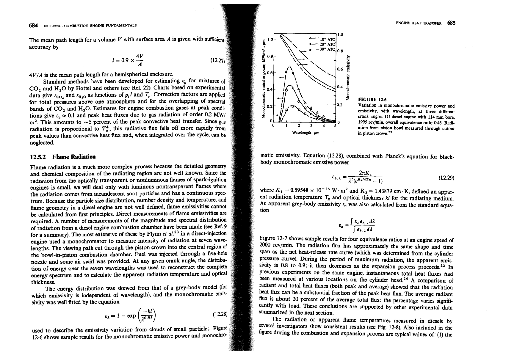
Variation in monochromatic emissive power
and
emissivity, with wavelength, at
three
different
tions give
E,
rz 0.1 and peak heat fluxes due to gas radiation of order 0.2
MW/
crank angles.
DI
diesel engine with
114
mm
bore,
rn2.
This amounts to
-5
percent of the peak convective heat transfer. Since gas
1995
rcv/min, overall equivalence ratio
0.46.
Radi-
radiation is proportional to
Ti,
this radiative flux falls off more rapidly from
ation from piston bowl measured through cutout
peak values than convective heat flux and, when integrated over the cycle, can
be
Wavelength,
Fm
in piston crown.23
neglected.
125.2
Flame
Radiation
matic emissivity. Equation (12.28), combined with Planck's equation for black-
body monochromatic emissive power
Flame radiation is a much more complex process because the detailed geometry
and chemical of the radiating region are not well known. Since the
2xK1
radiation from the optically transparent or nonluminous flames of spark-ignition
eb.
1
=
A~(~K~/~TR
-
1)
(12.29)
engines is small, we will deal only with luminous nontransparent flames where
the radiation comes from incandescent soot particles and has a continuous spec-
where K1
=
0.59548
x
W.mZ
and
K,
=
1.43879
cm
.K,
defined an appar-
tr-. Because the particle size distribution, number density and temperature, and
ent radiation temperature
TR and optical thickness
kl
for the radiating medium.
flame geometry in a diesel engine are not well defined, flame emissivities cannot
An apparent grey-body emissivity
E,
was also calculated from the standard qua-
be
calculated from first principles. Direct measurements of flame emissivities are
required. A number of measurements of the magnitude and spectral distribution
of radiation from a diesel engine combustion chamber have been made (see ~ef.
9
&,
=
j
e.4 eb,
1
for a summary). The most extensive of these by Flynn
et
al.13 in a direct-injection
.I'
eb. AdA
engine used a monochromator to measure intensity of radiation at seven wave-
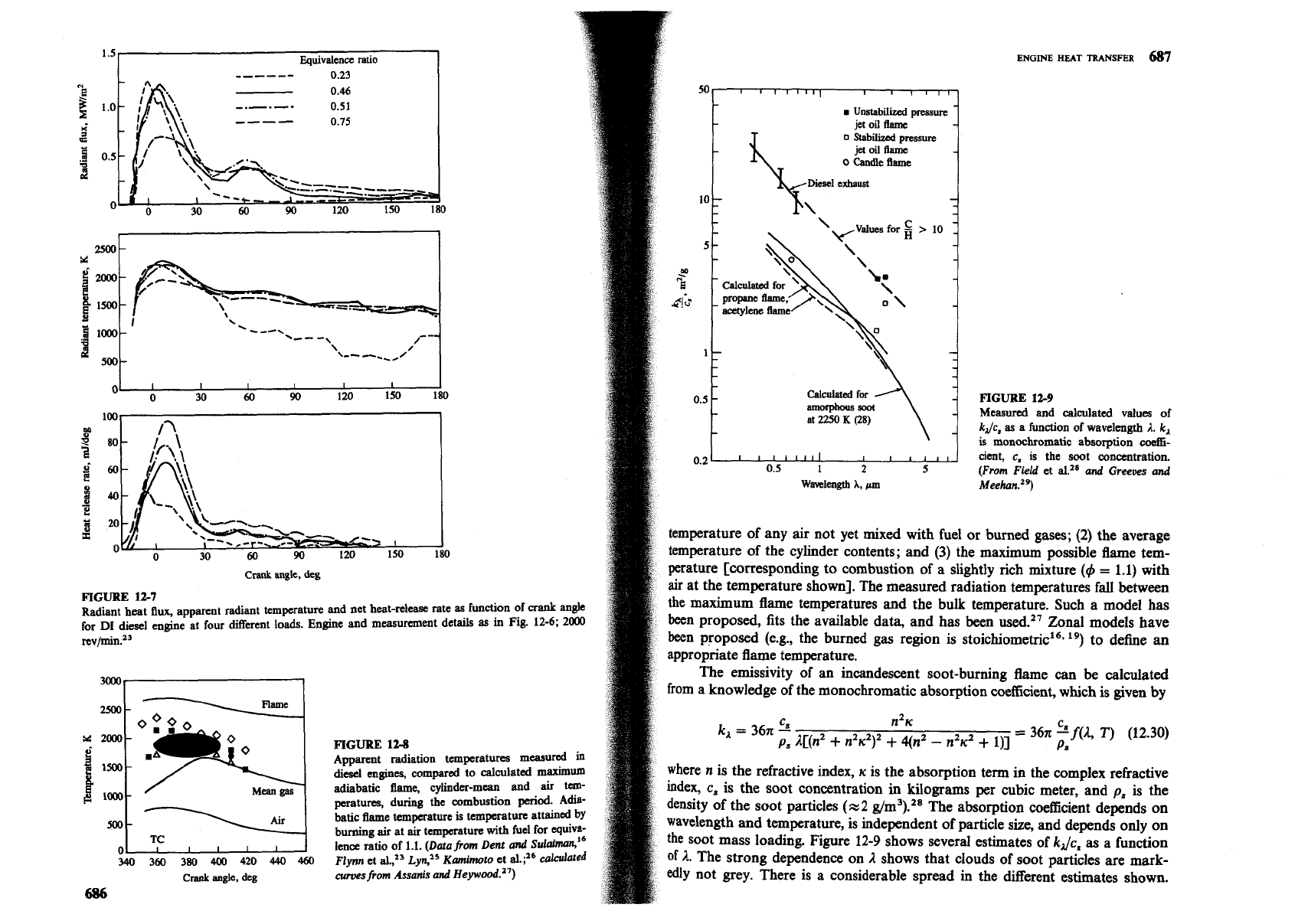
Figure 12-7 shows sample results for four equivalence ratios at an engine speed of
lengths. The viewing path cut through the piston crown into the central region
of
2000
revbin. The radiation flux has approximately the same shape and time
the bowl-in-piston combustion chamber. Fuel was injected through a five-hole
span
as
the net heat-release rate curve (which was determined from the cylinder
nozde and some
air
swirl was provided. At any given crank angle, the distribu-
Pressure curve). During the period of maximum radiation, the apparent emis-
tion of energy over the seven wavelengths was
used
to reconstruct the complete
sivit~ is 0.8 to 0.9; it then decreases as the expansion process proceeds.2J
I~
energy spectrum and to calculate the apparent radiation temperature and optical
previous experiments On the same engine, instantaneous total heat fluxes had
thickness.
been measured at various locations on the cylinder head.14
A
comparison
of
The energy distribution was skewed from that of a grey-body model (for
radiant and total heat fluxes (both peak and average) showed that the radiation
which emissivity is independent of wavelength), and the monochromatic emis-
heat flux can
be
a substantial fraction of the peak heat flux. The average radiant
sivity was well fitted by the equation
flux
is about 20 Percent of the average total flux: the percentage varies signifi-
cantly with load. These conclusions are supported by other experimental data
e1
=
I
-
exp
($)
summarized in the next section.
The radiation or apparent flame temperatures measured in diesels by
used to describe the emissivity variation from clouds of small particles. Figure
several investigators show consistent results (see Fig. 12-8). ~l~~ included.in the
12-6 shows sample results for the monochromatic emissive power and monochro-
figure during the combustion and expansion process are typical values of: (1) the
ENGINE
HEAT
TRANSFER
687
Equvalence
rauo
------
0
23
-.-.--
0
51
rn
Unstabll~zed
pressure
----
0
75
-
-
a
A
I
I
I
I
1
30
60
90
120 150 180
-
FIGURE
12-9
- Measured and calculated values of
-
k
Jc,
as a funct~on of wavelength
A.
k,
IS
monochromatic absorption
coeffi-
ctent,
c,
1s
the
soot concentration.
(From Field
et
a1
and
Greeves
and
Wavelength
A,
pm
Meeh~n.~~)
temperature of any air not yet mixed with fuel or burned gases;
(2)
the average
temperature of the cylinder contents; and (3) the maximum possible flame tem-
Crank
angk,
deg
perature [corresponding to combustion of a slightly rich mixture
(4
=
1.1) with
air
at the temperature shown]. The measured radiation temperatures fall between
FIGURE
127
~~di~~t heat
flux
apparent radiant temperature and net heat-release rate as
function
of
crank
angle
the maximum flame temperatures and the bulk temperature. Such a model has
for
DI
desel enme at
few
different loads. Enlgne and measurement det&
as
m
Fig.
12-6; 2000
been proposed, fits the available data, and has been used.27 Zonal models have
rev/rmn.Z3
been proposed (e.g., the burned
gas
region is stoichi~metric'~*
19)
to define an
appropriate flame temperature.
300-
The emissivity of an incandescent soot-burning flame
can
be calculated
m-
M
2000
0
FIGURE
128
PI
1
lm-
MA
Apparent radiatton temperatures masur*
*
did eng~nes, compared to calculated
maximum
where n is the refractive index,
K
is the absorption term in the complex refractive
B
lalo-
M~.,,
gas
adiabatic
flame,
cylinder-mean and air tm-
index,
c,
is the soot concentration
in
kilograms per cubic meter, and
p,
is the
peratures, during the combustion
perid.
Adla-
density of the soot particles (x2 g/m3).28 The absorption coefficient depends on
Ar
batic
be
temperature
IS
temperature attam*
by
500-
burning air at ur temperature
with
fuel for cquiva-
wavelength and temperature, is independent of particle size, and depends only on
TC
I
I
I
I
I
lena ratio of
1.1.
(~atafrom Dent
and
sulmi6
the soot mass loading. Figure 12-9 shows several estimates of
kJc,
as
a function
0
340
360
380 400
420
440
460
Flym
et
d.,2=
~yn,'~ Kamimoto
et al.;16
ca*ed
of
A.
The strong dependence on
2
shows that clouds of soot particles are mark-
crank
angle,
deg
curwsfrom Assarus and Heyw~od.~')
edly not grey. There is a considerable spread in the different estimates shown.
686
\
Fkil.2
0;to
-
OOO
from a knowledge of the monochromatic absorption coefficient, which is given by
n2~')'
+
4(n2
-
n2u2
+
I)]
=
36x
c"
f(2,
T)
(12.30)
688
INTERNAL COMBUSTION ENGINE FUNDAMENTALS
ENGINE
HEAT
TRANSFER
689
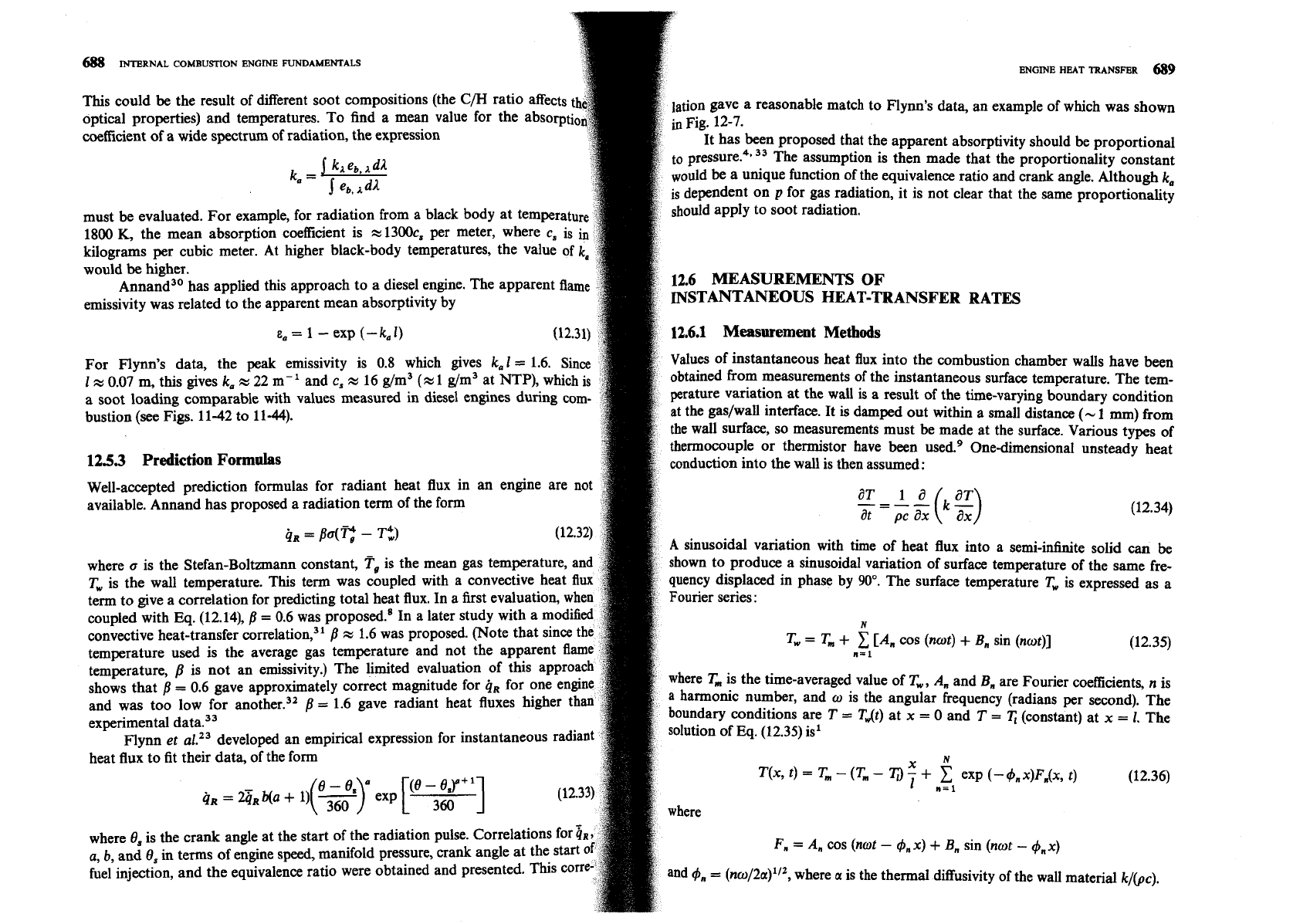
This could be the result of different soot compositions (the
C/H
ratio a
lation gave a reasonable match to Flynn's data, an example of which was shown
optical properties) and temperatures. To find a mean value for the
absorpt
coefiicient of a wide spectrum of radiation, the expression
It has been proposed that the apparent absorptivity should be proportional
j
kn
eb,
1
dl
to pressure.4p
33
The assumption is then made that the proportionality constant
ka
=
~ould be a unique function of the equivalence ratio and crank angle. Although
ka
j
eb+
A
is dependent on p for gas radiation, it is not clear that the same proportionality
must be evaluated. For example, for radiation from a black body at temperah
should apply to soot radiation.
1800
K, the mean absorption coefficient is
x
1300c, per meter, where c, is
kilograms per cubic meter. At higher black-body temperatures, the value of
would
be
higher.
Annand30 has applied this approach to a diesel engine. The apparent flam
12.6
MEASUREMENTS
OF
emissivity was related to the apparent mean absorptivity by
INSTANTANEOUS HEAT-TRANSFER
RATES
E,
=
1
-
exp (-k,l)
12.6.1
Measurement
Methods
For Flynn's data, the peak emissivity is 0.8 which gives
kal
=
1.6.
Values of instantaneous heat flux into the combustion chamber walls have been
1
x
0.07 m, this gives
k,
x
22
m-
'
and c,
x
16 g/m3 (x 1 g/m3 at NTP), wh
obtained from measurements of the instantaneous surface temperature. The tem-
a soot loading comparable with values measured in diesel engines during
perature variation at the wall is a result of the time-varying boundary condition
bustion
(see
Figs. 11-42 to 11-44).
at the gaslwall interface. It
is
damped out within a small distance
(-
1
mm) from
the wall surface, so measurements must be made at the surface. Various types of
thermocouple or thermistor have been used.g One-dimensional unsteady heat
12.5.3
Prediction Formdas
conduction into the wall is then assumed:
Well-accepted prediction formulas for radiant heat flux in an engine are n
available. Annand has proposed a radiation term of the form
----kg)
a~
-
1
a
at ax
(12.34)
41
=
pO(q
-
A
sinusoidal variation with time of heat flux into a semi-infinite solid can
be
where
a
is the Stefan-Boltzmann constant,
Tg
is the mean gas temperatu
shown to produce a sinusoidal variation of surface temperature of the same fre-
Tw
is the wall temperature. This term was coupled with a convecti
quency displaced in phase by
90".
The surface temperature
Tw
is expressed as a
term to give a correlation for predicting total heat flux. In a first evalua
Fourier series
:
coupled with Eq. (12.14),
/3
=
0.6 was prop~sed.~ In a later study with
N
convective heat-transfer ~orrelation,~~
fi
x
1.6 was proposed. (Note that si
Tw
=
T,
+
[A,
cos
(not)
+
B, sin (not)]
temperature used is the average gas temperature and not the apparent
fl
n=l
(12.35)
temperature,
p
is not an emissivity.) The limited evaluation of this a
shows that
j
=
0.6 gave approximately correct magnitude for
qR
for one e
where
T,
is the time-averaged value of
Tw
,
A, and B, are Fourier coefficients, n is
and was too low for another.32
=
1.6 gave radiant heat fluxes higher
a harmonic number, and w is the angular frequency (radians per second). The
experimental data.33
boundary conditions are
T
=
T,t)
at
x
=
0 and
T
=
T,
(constant) at
=
1.
The
nynn et al.23 developed an empirical expression for instantaneous radia
solution of
Eq.
(12.35) is1
heat flux to fit their data, of the form
X
T(x,
t)
=
T,
-
(T,,
-
'I;)
-
+
exp
(-
4,x)F,(x,
t)
e-e,
a (e-ej+l
1
"=I (12.36)
h
=
2bR
Ma
+
'I(=)
exp
[
360
]
where 8, is the crank angle at the start of the radiation pulse. Correlatio
a,
b,
and
8,
in terms of engine speed, manifold pressure, crank angle at the start
F,
=
A,
cos (not
-
4,x)
+
B, sin (not
-
4,x)
fuel injection, and the equivalence ratio were obtained and presented. This
tor
and
4,
=
(no/2a)'I2, where
a
is the thermal diffusivity of the wall material k/(pc).
