Heywood J.B. Internal Combustion Engines Fundamentals
Подождите немного. Документ загружается.

590
INTERNAL COMBUSTlON ENGINE FUNDAMENTALS
POLLUTANT
FORMATION
AND CONTROL
591
the prechamber of a Comet swirl chamber ID1 engine.21 The ga
rapidly becomes stoichiometric or fuel-rich. Composition nonuniformitie
the prechamber are substantial. Peak NO concentrations, as expected, c
spond approximately to locally stoichiometric regions. Because the mixtu
remains fuel-rich in the prechamber as the burned gases expand (after th
peak pressure which occurs between
6
and 10" ATC), substantial NO dec
tion within the prechamber can occur. However, by this time much of the gas
(and NO) in the prechamber has been transferred to the main chamber where
freezing of the NO chemistry will occur. Cylinder-gas dumping experiments,
where both main chamber and prechamber gases were dumped and quenched,
confirm this description. Cylinder average NO concentrations, determined by
rapidly opening a diaphram which separated the engine cylinder from an eva~
A
0.52
dm3
uated tank at predetermined points in the cycle of an otherwise normally oper-
YU
and
Shahed
0.01-
'
"
"
I
I
0.01
ated ID1 engine, rise rapidly once combustion starts, until the NO chemistry
is
llllll
3.4 3.6 3.8 4.0 4.2 4.4 4.6
3.4 3.6 3.8 4.0 4.2 4.4 4.6 4.8
effectively frozen at about 15" ATC. Little net NO decomposition occurs.22 Heat-
-
Io4,
10~1~
release-rate diagrams obtained from pressure data analysis for the same ID1
TI
engine indicate that combustion is only about one-half complete at the time the
(b)
NO formation process ceases.
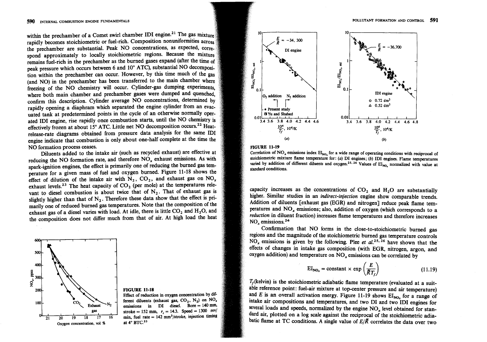
FIGURE
11-19
Diluents added to the intake air (such as recycled exhaust) are effective at
orr relation
of NO, emissions index EINOx for a wide range of operating conditions with reciprocal
of
reducing the NO formation rate, and therefore NO, exhaust emissions. As with
stoichiometric mixture flame temperature for:
(a)
DI engines;
(b)
ID1 engines. Flame temperatures
spark-ignition engines, the effect is primarily one of reducing the burned gas tem-
varied
standard by conditions. addition of different diluents and oxygen.25.
l6
Values of EIMS nomalized with Value at
perature for a given mass of fuel and oxygen burned. Figure 11-18 shows the
effect of dilution of the intake air with N,, CO,, and exhaust gas on NO,
exhaust
levels.23 The heat capacity of CO, (per mole) at the temperatures rele-
vant
to diesel combustion is about twice that of N2. That of exhaust gas is
capacity increases as the concentrations of CO, and H20 are substantially
slightly higher than that of N,. Therefore these data show that the effect is Pi-
higher.
Similar
studies in an
indirect-injection
engine show comparable trends.
rnaGly one of reduced burned gas temperatures. Note that the composition of the
Addition of diluents [exhaust gas (EGR) and nitrogen] reduce peak flame tem-
exhaust gas of a diesel varies with load. At idle, there is little CO2 and H20, and
peratures and NO, emissions; also, addition of oxygen (which corresponds to a
the
does not differ much from that of air. At
high
load the heat
reduction
in diluent fraction) increases flame temperatures and therefore increases
C~~firmation that NO forms in the close-to-stoi~hiometri~ burned gas
regions and the magnitude of the stoichiometric burned gas temperature controls
NO, emissions is given by the following. Plee
et
a1.25.26 have shown that the
effects of changes in intake gas composition (with EGR, nitrogen, argon, and
oxygen addition) and temperature on NO, emissions can be correlated by
EINOx
=
constant
x
exp
(1 1.19)
Tj&elvin) is the stoichiometric adiabatic flame temperature (evaluated at a suit-
FIGURE
11-18
able reference point: fuel-air mixture at topcenter pressure and
air
temperature)
Effect of reduction
in
oxygen concentration by
dif-
and
E
is an overall activation energy. Figure 11-19 shows
for a range of
ferent diluents (exhaust
gas,
CO,,
N,)
on
NOx
intake air CO~POS~~~O~S and temperatures, and two DI and two ID1 engines for
emissions in DI diesel. Bore
=
140
mm,
stroke
=
152
nun,
r,
=
14.3.
Speed
=
1300
rev/
several loads and speeds, normalized by the engine NO, level obtained for stan-
600
500-
400-
L
300-
0"
z
200
100
O*
2;
;9
1'8
i7
I;
rain,
fuel
rate
=
142 mm3/stroke, injection timing dard air, plotted on a log scale against the reciprocal of the stoichiometric
oxygen concentration,
ml
96
at 4' BTC.'"
batic flame at TC conditions.
A
single value of
~/k?
correlates the data over two
1
I
I
I
I
I
-
-
-
-
-
N2
-
P
mole fraction.
Since spark-ignition engines often operate close to stoichiometric at part
load and fuel rich at full load (see Sec. 7.1), CO emissions are significant and must
be controlled. Diesels, however, always operate well on the lean side of stoichio-
metric; CO emissions from diesels are low enough to
be
unimportant, therefore,
and will not be discussed further.
592
INTERNAL
COMBUSTION
ENGINE
FUNDAMENTALS
orders of magnitude. There is, of course, some scatter since the model used i
overly simple, and load, speed, and other engine design and operating parameters
affect the process. The overriding importance of the burned gas temperature
of close-to-stoichiometric mixture is clear, however.
113
CARBON
MONOXIDE
Carbon monoxide (CO) emissions from internal combustion engines are con-
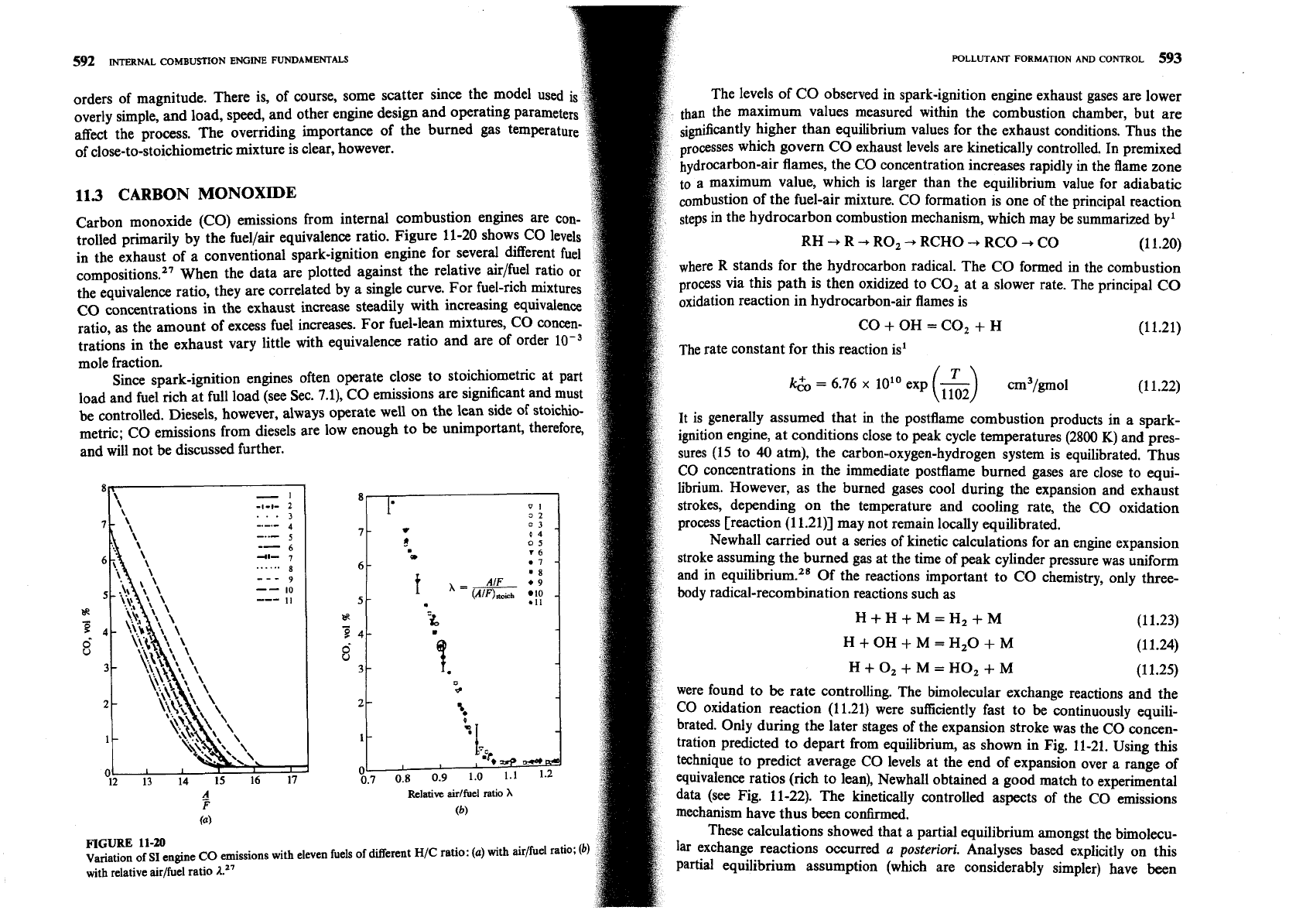
trolled primarily by the fuellair equivalence ratio. Figure 11-20 shows CO levels
in the exhaust of a conventional spark-ignition engine for several different fuel
compositions.27 When the data are plotted against the relative air/fuel ratio or
the equivalence ratio, they are correlated by a single curve. For fuel-rich mixtures
CO concentrations in the exhaust increase steadily with increasing equivalence
ratio, as the amount of excess fuel increases. For fuel-lean mixtures, CO concen-
trations in the exhaust vary little with equivalence ratio and are of order
10-3
4
!
---
Variation of
SI
engine CO emissions with eleven fuels of different H/C ratio:
(a)
with
aidfuel ratio;
(b
with
relative air/fuel ratio
1.''
OF-
,
I
Relative
aidfuel
ratio
h
(6)
POLLUTANT
FORMATION
AND
CONTROL
593
The levels of CO observed in spark-ignition engine exhaust gases are lower
than the maximum values measured within the combustion chamber, but are
higher than equilibrium values for the exhaust conditions. Thus
the
processes which govern CO exhaust levels are kinetically controlled. In premixed
hydrocarbon-air flames, the CO concentration increases rapidly
in
the flame zone
to a maximum value, which is larger than the equilibrium value for adiabatic
of the fuel-air mixture. CO formation is one of the principal reaction
steps in the hydrocarbon combustion mechanism, which may
be
summarized by1
RH-,R-+R02-+RCHO-rRCO+C0
(1 1.20)
where
R
stands for the hydrocarbon radical. The CO formed in the combustion
process via this path is then oxidized to CO, at a slower rate. The principal CO
oxidation reaction in hydrocarbon-air flames is
CO+OH=C02+H (1 1.21)
The rate constant for this reaction is'
kb,
=
6.76
x
101•‹ exp
(1 1.22)
~t is generally assumed that in the postflame combustion products in a spark-
ignition engine, at conditions close to peak cycle temperatures (2800
K)
and pres-
sures (15 to
40
atm), the carbon-oxygen-hydrogen system is equilibrated. Thus
CO concentrations in the immediate postflame burned gases are close to equi-
librium. However, as the burned gases cool during the expansion and exhaust
strokes, depending on the temperature and cooling rate, the CO oxidation
process [reaction (1
1.21)] may not remain locally equilibrated.
Newhall carried out a series of kinetic calculations for an engine expansion
stroke assuming the burned gas at the time of peak cylinder pressure was uniform
and in
equilibri~m.~~ Of the reactions important to CO chemistry, only three-
body radical-recombination reactions such as
H+H+M=H2+M
(1 1.23)
H+OH+M=H,O+M
(1 1.24)
H+O,+M=HO,+M
(1 1.25)
were found to
be
rate controlling. The bimolecular exchange reactions and the
CO
oxidation reaction (11.21) were sufficiently fast to be continuously equili-
brated. Only during the later stages of the expansion stroke was the CO concen-
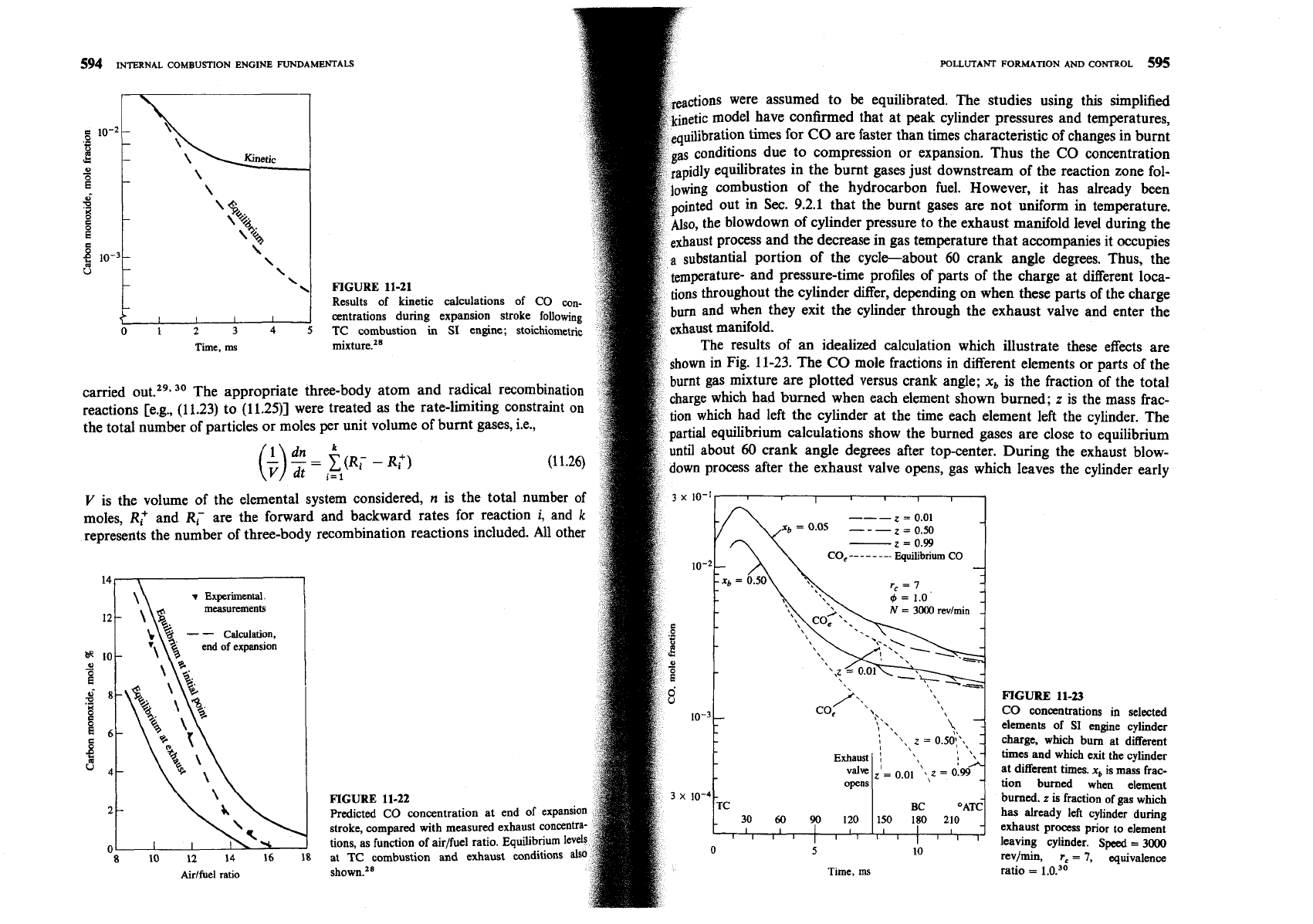
tration predicted to depart from equilibrium, as shown in Fig. 11-21. Using this
technique to predict average CO levels at the end of expansion over a range of
equivalence ratios (rich to lean), Newhall obtained a good match to experimental
data (see Fig. 11-22). The kinetically controlled aspects of the CO emissions
mechanism have thus been
confirmed.
These calculations showed that a partial equilibrium amongst the bimolecu-
lar exchange reactions occurred
a
posteriori.
Analyses based explicitly on this
partial equilibrium assumption (which are considerably simpler) have been
594
INTERNAL COMBUSTION ENGINE FUNDAME~TALS WLLUTANT FORMATION AND CONTROL
595
es using this simplified
pressures and temperatures,
s in the burnt gases just downstream of the reaction zone fol-
wever, it has already been
not uniform in temperature.
ust manifold level during
the
companies it occupies
gle degrees. Thus, the
the charge at different loca-
\
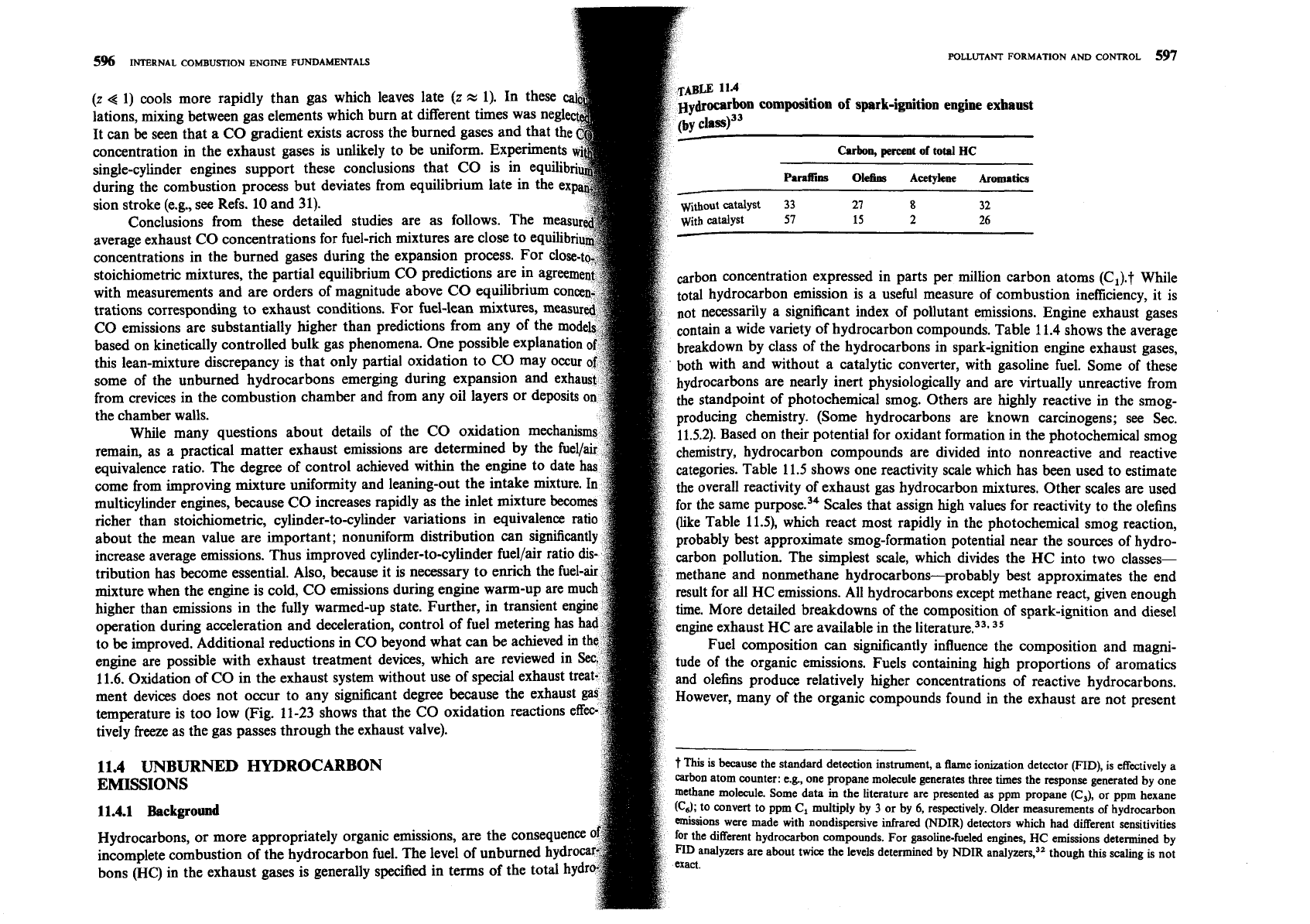
FIGURE
11-21
hen these parts of the charge
exhaust valve and enter the
nt elements or parts of the
are plotted versus crank angle;
x,
is the fraction of the total
carried out.29s
30
The appropriate three-body atom and radical recombination
burned when each element shown burned;
z
is the mass frac-
reactions [e.g.,
(11.23)
to
(11.25)]
were treated as the rate-limiting constraint on
ent left the cylinder. The
the total number of particles or moles
per
unit volume of burnt gases, i.e.,
are close to equilibrium
uring the exhaust blow-
leaves the cylinder early
moles,
R,?
and
R;
are the forward and backward rates for reaction
i,
and
k
represents the number of three-body recombination reactions included.
All
other
CO,
--
-
-
-
---
Equilibrium
CO
-
v
Experimental.
measurements
FIGURE
11-23
hich
bum at different
aUSt
process
prior
to
element
leaving cylinder.
Speed
=
3000
rev/min,
r,
=
7,
equivalence
Time,
ms
ratio
=
5%
INTERNAL COMBUSTION ENGINE FUNDAMENTALS
POLLUTANT FORMATION AND CONTROL
597
(z
g
1) cools more rapidly than gas which leaves late (z
zl
1). In
lations, mixing between gas elements which burn at different times was
It can be seen that a CO gradient exists across the burned gases and th
concentration in the exhaust gases is unlikely to be uniform. Experiments
single-cylinder engines support these conclusions that CO is in equilib
P.mffii
Ole6m
Acetylene
Aromatics
during the combustion process but deviates from equilibrium late in the ex
sion stroke (e.g., see Refs. 10 and 31).
without catalyst
33
27
8
32
Conclusions from these detailed studies are as follo
average exhaust CO concentrations for fuel-rich mixtures are close to equilib
concentrations in the burned gases during the expansion process.
FO
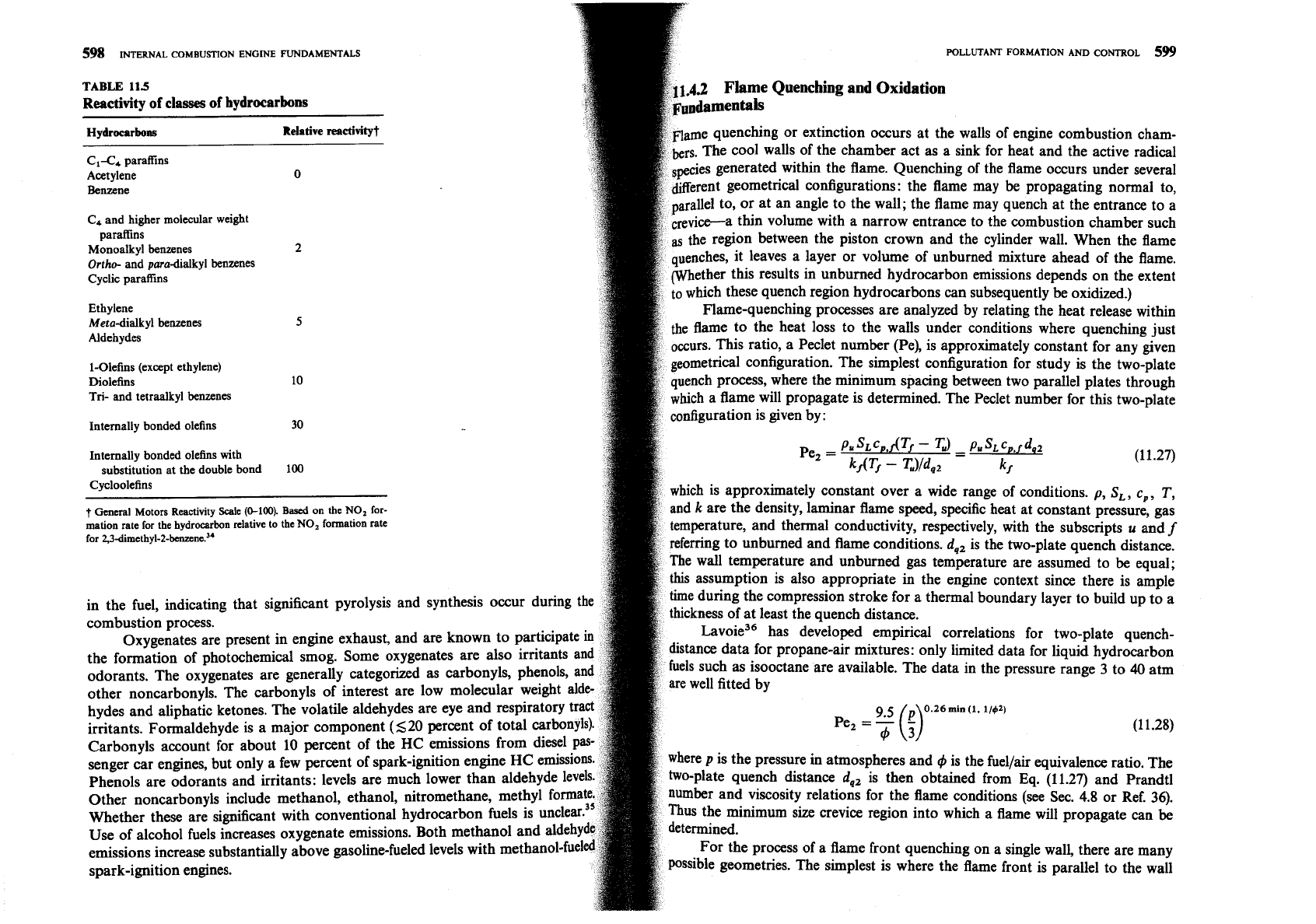
stoichiometric mixtures, the partial equilibrium CO predictions are in ag carbon concentration expressed in parts per million carbon atoms (C,).t While
with measurements and are orders of magnitude above CO equilibrium
total hydrocarbon emission is a useful measure of combustion inefficiency, it is
trations corresponding to exhaust conditions. For fuel-lean mixtures,
not necessarily a significant index of pollutant emissions. Engine exhaust gases
CO emissions are substantially higher than predictions from an
contain a wide variety of hydrocarbon compounds. Table 11.4 shows the average
based on kinetically controlled bulk gas phenomena. One possibl breakdown by class of the hydrocarbons in spark-ignition engine exhaust gases,
this lean-mixture discrepancy is that only partial oxidation to CO m
both with and without a catalytic converter, with gasoline fuel. Some of these
some of the unburned hydrocarbons emerging during expansion and ex
hydrocarbons are nearly inert physiologically and are virtually unreactive from
from crevices in the combustion chamber and from any oil layers or deposi
the standpoint of photochemical smog. Others are highly reactive in the smog-
the chamber walls.
~roducing chemistry. (Some hydrocarbons are known carcinogens; see Sec.
While many questions about details of the CO oxidation
11.5.2). Based on their potential for oxidant formation in the photochemical smog
remain, as a practical matter exhaust emissions are determined by the fuel
chemistry, hydrocarbon compounds are divided into nonreactive and reactive
equivalence ratio. The degree of control achieved within the engine to date
categories. Table 11.5 shows one reactivity scale which has been used to estimate
come from improving mixture uniformity
and
leaning-out the intake mixture.
the overall reactivity of exhaust gas hydrocarbon mixtures. Other scales are used
multicylinder engines, because CO increases rapidly as the inlet mixt for the same purpo~e.'~ Scales that assign high values for reactivity to the olefins
richer than stoichiometric, cylinder-to-cylinder variations in equivalence r
(like Table 11.5), which react most rapidly in the photochemical smog reaction,
about the mean value are important; nonuniform distribution can significa
probably best approximate smog-formation potential near the sources of hydro-
increase average emissions. Thus improved cylinder-to-cylinder
fuellair ratio
carbon pollution. The simplest scale, which divides the HC into two classes-
tribution has become essential. Also, because it is necessary to enrich the fuel-
methane and
nonrnethane hydrocarbons-probably best approximates the end
mixture when the engine is cold, CO emissions during engine result for all HC emissions. All hydrocarbons except methane react, given enough
higher than emissions in the fully warmed-up state. Further,
time. More detailed breakdowns of the composition of spark-ignition and diesel
operation during acceleration and deceleration, control of fuel engine exhaust HC are available in the literature.".
35
to
be
improved. Additional reductions in CO beyond what can
be
a
Fuel composition can significantly influence the composition and magni-
engine are possible with exhaust treatment devices, which are reviewed in
tude of the organic emissions. Fuels containing high proportions of aromatics
11.6. Oxidation of CO in the exhaust system without use of special exhaust tr
and olefins produce relatively higher concentrations of reactive hydrocarbons.
ment devices does not occur to any significant degree because the exhaust
However, many of the organic compounds found in the exhaust are not present
temperature is too low (Fig. 11-23 shows that the CO oxidation reactions e
tively freeze as the gas passes through the exhaust valve).
11.4 UNBURNED HYDROCARBON
t
This
is
because the standard detection instrument, a flame ionization detector
(FID),
is effectively a
EMISSIONS
carbon atom counter: e.g, one propane molecule generates three times the response generated by one
methane molecule. Some data in the literature are presented
as
ppm propane
(C,),
or ppm hexane
11.4.1
B8ckg01111d
urements of hydrocarbon
had different sensitivities
Hydrocarbons, or more appropriately organic emissions, are the cons
different hydrocarbon compounds. For gasoline-fueled engines,
HC
emissions determined by
incomplete combustion of the hydrocarbon fuel. The level of unburned
dyzers
are about twice the levels determined by
NDIR
andyzer~,'~ though this scaling is not
bons (HC) in the exhaust gases is generally specified in terms of the to
598
INTERNAL
COMBUSTION
ENGINE
FUNDAMENTALS
POLLUTANT FORMATION AND CONTROL
599
TABLE
11.5
nching and Oxidation
Reactivity
of
classes
of
hydrocarbons
Hydrocarbons Relative
reactivity?
C1C4 parafins
Acetylene
o
hin the flame. Quenching of the flame occurs under several
Benzene
trical configurations: the flame may be propagating normal to,
or at an angle to the wall; the flame may quench at the entrance to a
C4 and higher molecular weight
thin volume with a narrow entrance to the combustion chamber such
parafins
2
tween the piston crown and the cylinder wall. When the flame
Monoalkyl benzenes
Ortho-
and pamadialkyl benzenes
Cyclic paraff~ns
bon emissions depends on the extent
can subsequently be oxidized.)
Ethylene
hing processes are analyzed by relating the heat release within
Meta-dialkyl benzenes
5
t loss to the walls under conditions where quenching just
Aldehydes
a Peclet number (Pe), is approximately constant for any given
1-olefins (except ethylene)
etrical configuration. The simplest configuration for study is the two-plate
Diolefins 10
ch process, where the minimum spacing between two parallel plates through
Tri-
and tetraalkyl benzenes
ch a flame will propagate is determined. The Peclet number for this two-plate
30
figuration is given by:
Internally bonded olefins
Internally bonded olefins with
substitution at the double bond
100
Cycloolefins
hich is approximately constant over a wide range of conditions.
p,
S,,
c,,
T,
t
General Motors Reactivity Scale
(0-100).
Based
on the
NO,
for-
k
are the density, laminar flame speed, specific heat at constant pressure, gas
mation rate for the hydrocarbon relative to the
NO,
fonnation rate
onductivity, respectively, with the subscripts
u
and
f
for 2,3dimethyl-2-benzene?'
ed and flame conditions.
d,,
is the two-plate quench distance.
re and unburned gas temperature are assumed to be equal;
ropriate in the engine context since there is ample
in the fuel, indicating that significant pyrolysis and synthesis occur during
the
stroke for a thermal boundary layer to build up to a
combustion process.
Oxygenates are present in engine exhaust, and are known to partici
al correlations for two-plate quench-
the formation of photochemical smog. Some oxygenates are also irrita
nly limited data for liquid hydrocarbon
odorants. The oxygenates are generally categorized as carbonyls, phen
els such as isooctane are available. The data in the pressure range 3 to
40
atm
other noncarbonyls. The carbonyls of interest are low molecular weight
hydes and aliphatic ketones. The volatile aldehydes are eye and res
irritants. Formaldehyde is a major component (520 percent of total
Carbonyls account for about 10 percent of the
HC
emissions fro
senger car engines, but only a few percent of spark-ignition engine
where
P
is the pressure in atmospheres and
4
is the fuel/& equivalence ratio. The
Phenols are odorants and irritants: levels are much lower than alde
two-plate quench distance
d,,
is then obtained from Eq. (11.27) and Prandtl
Other noncarbonyls include methanol, ethanol, nitromethane, met
number and viscosity relations for the flame conditions (see Sec.
4.8
or Ref. 36).
Whether these are significant with conventional hydrocarbon fuels is unclear
ize crevice region into which a flame will propagate can
be
Use of alcohol fuels increases oxygenate emissions. Both methanol and aldehy
emissions increase substantially above gasoline-fueled levels with methanol-fuel
For the process of a flame front quenching on a single wall, there are many
spark-ignition engines.
ssible geometries. The simplest is where the flame front is parallel to the wall
600
INTERNAL
COMBUSTION
ENGINE
FUNDAMENTALS
POLLUTANT
FORMATION
AND
CONTROL
601
and approaches it head on. The one-wall quench distance d,,, defined
as
hot reaction zone to the wall and heat released in the reaction zone by
position of closest approach of the reaction zone to the wall, scales with
fl
flame reactions. The second step is the postquench diffusion and oxidation
properties in a similar way to the two-plate quench distance. Thus, a one.
time scale of one or a few milliseconds after quenching. The
diffu-
Peclet number relation can be formed:
xidation process ultimately reduces the mass of wall quench
hydrocar-
ens
to several orders of magnitude below its value at the time of quenching.
Closed-vessel combustion experiments have also been used to show that oil
layers on the walls of the bomb cause an increase in residual unburned HC levels
where the subscript
u
denotes properties evaluated at unburned gas conditio
after combustion is complete. The additional HC that result in experiments with
Using the wall temperature as representative of the unburned gas
oil films present are primarily
(>
95
percent) fuel molecules, and are directly pro-
perature (because the thermal boundary-layer thickness is greater than t
prtional to the amount of oil placed on the walls of the reactor and the solu-
quench distances), Lavoie showed that
bility of the specific fuel in the oil. These results show that absorption of fuel in
d
Pe
the oil occurs prior to ignition. This dissolved fuel is then desorbed into the
A
=
-_L
=
0.2
burned gases well after combustion is complete. Thus fuel absorption into and
42
Pe2
from any oil layers is a potentially important engine
HC
mecha-
is a reasonable fit to the single-wall quench data. Typical two-wall quench
C
Emissions from Spark-Ignition
are, therefore, in the range 0.04 to 0.2 mm.
While a fraction of the fuel hydrocarbons can escape the
bustion process unburned or only partially reacted, oxidation of
Unburned hydrocarbon levels in the exhaust of a spark-ignition engine under
hydrocarbons can occur during the expansion and exhaust processes.
H
normal operating conditions are typically in the range 1000 to
3000
ppm C,. This
bon oxidation rates have been determined in a number of different stu
corresponds to between about 1 and
23 percent of the fuel flow into the engine;
several different empirical correlations of the data in the form of overall rea
the engine combustion efficiency is high. As indicated in Fig. 11-2, HC emissions
rate equations have been proposed. A reasonable fit to the experimental data
rise rapidly
as
the mixture becomes substantially richer than stoichiometric.
unburned
HC
burnup is the rate expression?
When combustion quality deteriorates, e.g., with very lean mixtures, HC emis-
sions can rise rapidly due to incomplete combustion or misfire in a fraction of the
engine's operating cycles. As outlined in Sec. 11.1, there are several mechanisms
that contribute to total HC emissions. Also, any HC escaping the primary com-
where
[
1
denotes concentration in moles per cubic centimeter,
%,,
and
jt,,
bustion process may oxidize in the expansion and exhaust processes. While a
the mole fractions of HC and
O,,
respectively,
t
is in seconds,
T
in kelvins,
complete description of the HC emissions process cannot yet be given, there are
the density term
(p/RT)
has units of moles per cubic centimeter. The
sufficient fundamental data available to indicate which mechanisms are likely to
the data about this equation is substantial, however.
be
most important, and thus how major engine variables influence HC emission
Studies of combustion of premixed fuel-air mixtures at high p
closed vessels or bombs have been useful in identifying the mechanism
Four possible HC emissions formation mechanisms for spark-ignition
hydrocarbons escape complete combustion. The residual unburned hy
where the fuel-air mixture is essentially premixed) have been proposed:
left in the bomb following a combustion experiment have been shown to
ame quenching at the combustion chamber walls, leaving a layer of
primarily from crevices in the bomb walls. Unburned HC levels w
rned fuel-air mixture adjacent to the wall; (2) the filling of crevice volumes
a1 to total crevice volume, and decreased to very low values
(-
10 p
urned mixture which, since the flame quenches at the crevice entrance,
the crevices were filled with solid material. Thus wall quench h
he primary combustion process;
(3)
absorption of fuel vapor into oil
apparently diffuse into the burned gases and oxidize following the quen
e cylinder wall during intake and compression, followed by desorp-
event.37 Analytical studies of the flame quenching process, and ~ost~uench
apor into the cylinder during expansion and exhaust;
(4)
incomplete
sion and oxidation with kinetic models of the hydrocarbon oxidatio
combustion in a fraction of the engine's operating cycles (either partial burning
in agreement with these bomb
data.38 Flame quenching can be thought of
ete misfire), occurring when combustion quality is poor (e.g., during
two-stage process. The first step is the extinction of the flame at a short dist
nts when
AIF,
EGR,
and spark timing may not be adequately
from the cold wall, determined by a balance between thermal conduction of
).
In addition, as deposits build up on the combustion chamber walls,
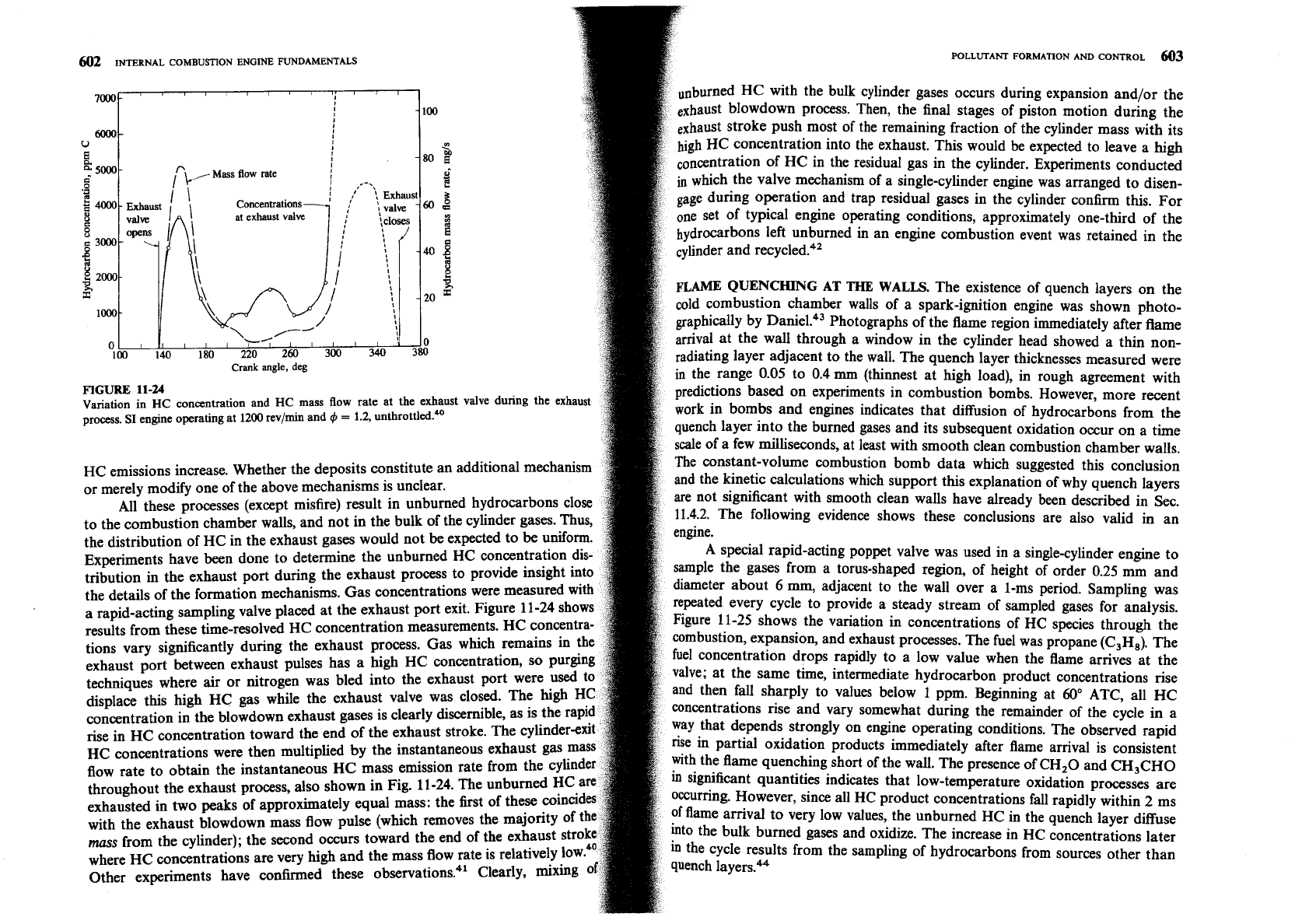
602
INTERNAL COMBUSTION ENGINE FUNDAMENTALS
4
Crank
angle,
deg
FIGURE
11-24
Variation in
HC
concentration and
HC
mass flow rate at the exhaust valve during the exhaust
process. SI engine operating at
1200
revlmin and
4
=
1.2,
unthrottled*
HC emissions increase. Whether the deposits constitute an additional mechanis
or merely modify one of the above mechanisms is unclear.
All these processes (except misfire) result in unburned hydrocarbons clo
to the combustion chamber walls, and not in the bulk of the cylinder gases. Thus,
the distribution of HC in the exhaust gases would not be expected to be uniform
Experiments have been done to determine the unburned HC concentration dis
tribution in the exhaust port during the exhaust process to provide insight into
the details of the formation mechanisms. Gas concentrations were measured wit
a rapid-acting sampling valve placed at the exhaust port exit. Figure 11-24 sho
results from these time-resolved HC concentration measurements. HC
concent
tions vary significantly during the exhaust process. Gas which remains in the
~xhaust
nort
between exhaust vulses has a high HC concentration, so
-
.
-
--
-
--
-
r---
techniques where air or nitrogen was bled
displace this high HC gas while the exha
concentration in the blowdown exhaust gases is clearly discernible, as is the
rise in HC concentration toward the end of the exhaust stroke. The cylinde
HC concentrations were then multiplied by the instantaneous exhaust gas
flow rate to obtain the instantaneous
HC mass emission rate from the cy
throughout the exhaust process, also shown in Fig. 11-24. The unburned HC
exhausted in two peaks of approximately equal mass: the first of these coinci
with the exhaust blowdown mass flow pulse (which removes the majority of
mcs
from
the cvlinder): the second occurs toward the end of the exhau;
.
.
- - -
-
-
-
.
-
-
,
-
where HC concentrations are very high and
Other experiments have confirmed these
rned HC with the bulk cylinder gases occurs during expansion and/or the
ust
blowdown process. Then, the final stages of piston motion during the
aust stroke push most of the remaining fraction of the cylinder mass with its
h
HC concentration into the exhaust. This would be expected to leave a
high
ation of HC in the residual gas in the cylinder. Experiments conducted
the valve mechanism of a single-cylinder engine was arranged to disen-
ng operation and trap residual gases in the cylinder confirm this. For
one set of typical engine operating conditions, approximately one-third of the
hydrocarbons left unburned in an engine combustion event was retained in the
1
i
cylinder and re~ycled.~'
g
20
L
I
0
340
380
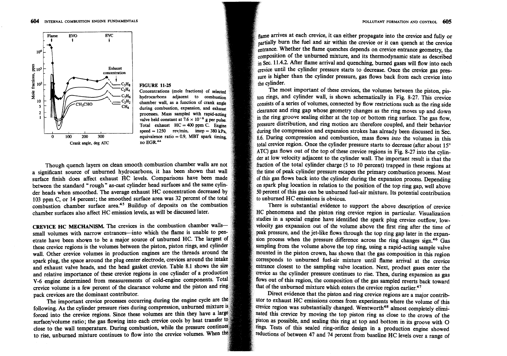
repeated every cycle to provide a steady stream of sampled gases
Figure 11-25 shows the variation in concentrations of HC species
combustion, expansion, and exhaust processes. The fuel was propane
fuel concentration drops rapidly to a low value when the flame a
into the exhaust port wer
ust valve was closed. The
..
.
the mass flow rate is relatively low.
observations?1 Clearly, mixing
FLAME
QUENCHING
AT
THE
WALLS.
The existence of quench layers on the
combustion chamber walls of a spark-ignition engine was shown photo-
pphically by Photographs of the flame region immediately after flame
arrival at the wall through a window in the cylinder head showed a thin non-
radiating layer adjacent to the wall. The quench layer thicknesses measured were
in
the range 0.05 to 0.4
mm
(thinnest at high load), in rough agreement with
predictions based on experiments in combustion bombs. However, more recent
work in bombs and engines indicates that diffusion of hydrocarbons from the
:h layer into the burned gases and its subsequent oxidation occur on a time
scale of a few milliseconds, at least with smooth clean combustion chamber walls.
The constant-volume combustion bomb data which suggested this conclusion
and the kinetic calculations which support this explanation of why quench layers
are not significant with smooth clean walls have alreadv been described
in
Sec.
11.4.2.
The following evidence shows these conclusions are also valid in an
engine.
A special rapid-acting poppet valve was used in a single-cylinder engine to
sample the gases from a torus-shaped region, of height of order 0.25 mm and
diameter about
6 mrn,
adjacent to the wall over a 1-ms period. Sampling was
for anal
through
'
(c3H8).
rrives at
ysis.
the
The
the
alve; at the same time, intermediate hydrocarbon product concentrations rise
then fall sharply to values below
1
ppm. Beginning at
60"
ATC, all HC
centrations rise and vary somewhat during the remainder of the cycle in a
ay that depends strongly on engine operating conditions. The observed rapid
in partial oxidation products immediately after flame arrival is consistent
the flame quenching short of the wall. The presence of
CH20 and CH3CH0
significant
quantities indicates that low-temperature oxidation processes are
ccurring. However, since all HC product concentrations fall rapidly within
2
ms
flame arrival to very low values, the unburned HC in the quench layer diffuse
o the bulk burned gases and oxidize. The increase in HC concentrations later
the cycle results from the sampling of hydrocarbons from sources other than
11m"oh
I-..-..-
44
604
INTERNAL
COMBUSTION
ENGINE
FUNDAMENTALS
POLLUTANT
FORMA~ON
AND
CONTROL
605
ame amves at each crevice, it can either propagate into the crevice and fully or
1 and air within the crevice or it can quench at the crevice
104
trance. Whether the flame quenches depends on crevice entrance geometry, the
m~osition of the unburned mixture, and its thermodynamic state as described
mval and quenching, burned gases will flow into each
g
I@
der pressure starts to decrease. Once the crevice gas pres-
d
re is higher than the cylinder pressure, gas flows back from each crevice into
g
I@
".
s
ant of these crevices, the volumes between the piston, pis-
g
n rings, and cylinder wall, is shown schematically in Fig.
8-27.
This crevice
10
5
nsists of a series of volumes, connected by flow restrictions such as the ring side
2
whose geometry changes as the ring moves up and down
I
ther at the top or bottom ring surface. The gas flow,
ng motion are therefore coupled, and their behavior
mpression and expansion strokes has already been discussed in Sec.
0
100
200
300
compression and combustion, mass flows into the volumes in this
Crank
angle, deg
ATC
no
EGR.U
region. Once the cylinder pressure starts to decrease (after about
15"
s out of the top of these crevice regions in Fig.
8-27
into the cylin-
nt to the cylinder wall. The important result is that the
Though quench layers on clean smooth combustion chamber walls are not
er charge
(5
to
10
percent) trapped in these regions at
a significant source of unburned hydrocarbons, it has been shown that wall
ressure escapes the primary combustion process. Most
surface finish does affect exhaust
I%2
levels. Comparisons have been made
the cylinder during the expansion process. Depending
between the standard "rough" as-cast cylinder head surfaces and the same cylin-
spark plug location
in
relation to the position of the top ring gap, well above
der heads when smoothed. The average exhaust HC concentration decreased by
percent of this gas can be unburned fuel-air mixture. Its potential contribution
103
ppm C, or
14
percent; the smoothed surface area was
32
percent of the total
unburned HC emissions is obvious.
combustion &amber surface area45 Buildup of deposits on the combustion
There is substantial evidence to support the above description of crevice
chamber surfaces also affect HC emission levels, as will be discussed later.
iston ring crevice region in particular. Visualization
have identified the spark plug crevice outflow, low-
CREVICE
HC
MECHANISM.
The crevices in the combustion chamber walls-
ansion out of the volume above the fist ring after the time of
small volumes with narrow entrances-into which the flame is un
d the jet-like flows through the top ring gap later in the expan-
etrate have been shown to be a major source of unburned HC. The
process when the pressure difference across the ring changes sign.46 Gas
these crevice regions is the volumes between the piston, piston rings, an
ling from the volume above the top ring, using a rapid-acting sample valve
wall. Other crevice volumes in production engines are the threads aroun
unted in the piston crown, has shown that the gas composition in this region
spark plug, the space around the plug center electrode, crevices arou
fuel-air mixture until flame arrival at the crevice
and exhaust valve heads, and the head gasket crevice. Table
8.1.
shows the
o
the sampling valve location. Next, product gases enter the
and relative importance of these crevice regions in one cylin
vice as the cylinder pressure continues to rise. Then, during expansion as gas
V-6
engine determined from measurements of cold-engine ComP
gion, the composition of the gas sampled reverts back toward
crevice volume is a few percent of the clearance volume and the
t of the unburned mixture which enters the crevice region earlier?'
pack crevices are the dominant contributor.
Direct evidence that the piston and ring crevice regions are a major contrib-
The important crevice processes occurring during the engine cycle are
r to exhaust HC emissions comes from experiments where the volume of this
following. As the cylinder pressure rises during compression, unb
substantially changed. Wentw~rth~~ almost completely elimi-
forced into the crevice regions. Since these volumes are thin they h
this crevice by moving the top piston ring as close to the crown of the
surface/volume ratio; the gas flowing into each crevice cools by heat
as possible, and sealing this ring at top and bottom
in
its groove with
0
close to the wall temperature. During combustion, while the P
sealed ring-orifice design in a production engine showed
to rise, unburned mixture continues to flow into the crevice v~hmes. When
uctions of between 47 and
74
percent from baseline HC levels over a range of
