Heywood J.B. Internal Combustion Engines Fundamentals
Подождите немного. Документ загружается.

the flame is especially important during the early stages of flame development
when the pressure rise due to combustion is too small to be detected.
These photographs show how the flame "ball," roughly spherical in shape,
grows steadily from the time of spark discharge. The effect of turbulence is
already visible in the convoluted flame surface in Fig.
9-14a.
The volume
enflamed behind the front continues to grow in a roughly spherical manner,
except where intersected by the chamber walls, as seen in Fig.
9-14b
and
c.
The
mass fraction burned and the associated pressure rise due to combustion become
significant by the time the flame front has traversed two-thirds to three-quarten
of the field of view. Note that the fraction of the cylinder filled with enflamed
charge is less than is suggested by the photos because the front of the flame is
approximately spherical and the cylinder has a square cross section. Maximum
cylinder pressure occurs close to the time the flame makes contact with the far
wall, as seen in Fig.
9-14e.
Finally, the unburned mixture ahead of and within the
front burns out and the density gradients associated with the flame reaction zone
disappear, clearing the field of view as shown in Fig.
9-14e
and$
A
useful relationship between the mass fraction burned,
xb(=mdm),
and the
volume fraction occupied by the burned gas,
yb(=
WV),
can
be
obtained from the
identities
and the ideal gas law:
While the density ratio
(pdp,)
does depend on the equivalence ratio, burned
ga~
fraction in the unburned mixture, gas temperature, and pressure, its value is close
to
4
for most spark-ignition engine operating conditions. Thus, the plot of
x,
against
y,
has a universal form,1•‹ as shown in Fig.
9-15.
This curve is an impor-
tant aid in interpreting flame geometry information.
Burned volume fraction,
yb
FIGURE
9-15
Relation between mass fraction burned
xb
and vd.
*
ume fraction burned
y,.
x,
is residual
m&
f*
?
ti~n.~
COMBUSTION
IN
SPARK-IGNITION
ENGINES
393
Crank angle, degrees from ignition
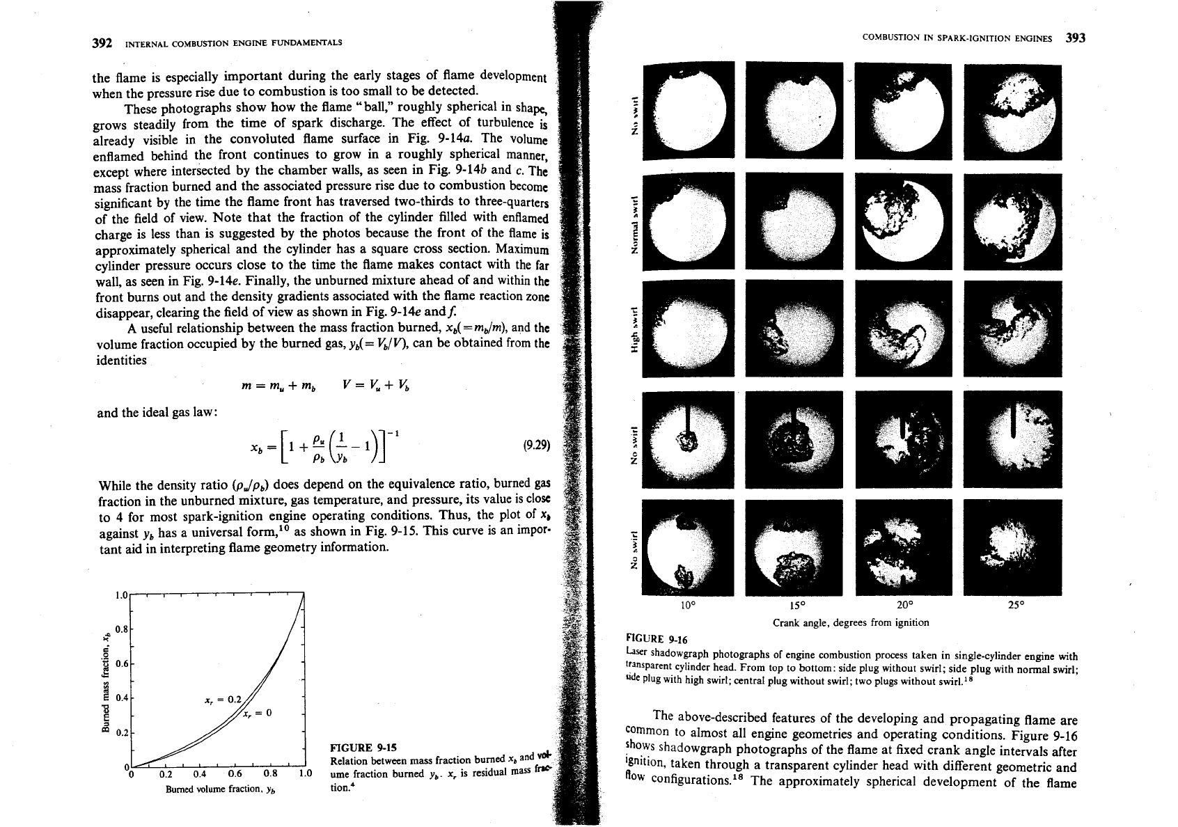
FIGURE
9-16
her
shadowgraph photographs of engine combustion process taken in single-cylinder engine with
"ansparent cylinder head. From top to bottom: side plug without swirl; side plug with normal swirl;
ude
plug with high swirl; central plug without swirl; two plugs without swirl.''
The above-described features of the developing and propagating flame are
common to almost all engine geometries and operating conditions. Figure
9-16
shows shadowgraph photographs of the flame at fixed crank angle intervals after
%nition, taken through a transparent cylinder head with different geometric and
flow configurations.18 The approximately spherical development of the flame
394
INTERNAL COMBUSTION ENGINE FUNDAMENTALS
from the vicinity of the spark plug, except where it intercepts the chamber
w
is evident for side and center ignition with one plug, and for ignition with
plugs in the absence of any intake generated swirl. With normal levels of s
the flame center is convected with the swirling flow, but the flame front
grows is still approximately spherical in shape. Only with unusually hi
swirl and aerodynamic stabilization of the flame at the spark plug location
d
the flame become stretched out and distorted by the flow in a major way.18
At any given flame radius, the geometry of the combustion chamber
ad
the spark plug location govern the flame front surface area-the area of
tk
approximately spherical surface corresponding to the leading edge of the
flw
contained by the piston, cylinder head, and cylinder wall. The larger this surf==
area, the greater the mass of fresh charge that can cross this surface and enter
flame zone. The photos in Fig. 9-16 illustrate the importance of flame area.
~h~
center plug location gives approximately twice the flame area of the side plu
geometry at a given flame radius, and burns about twice as fast (the fraction
the cylinder volume enflamed is about twice the size, at a fixed crank angle int
val after spark). The arrangement with two spark plugs at opposite sides oft
chamber is not significantly different in enflamed volume from the single ce
plug because, once the flame fronts are intersected by the cylinder wall, the
fl
front areas are comparable.
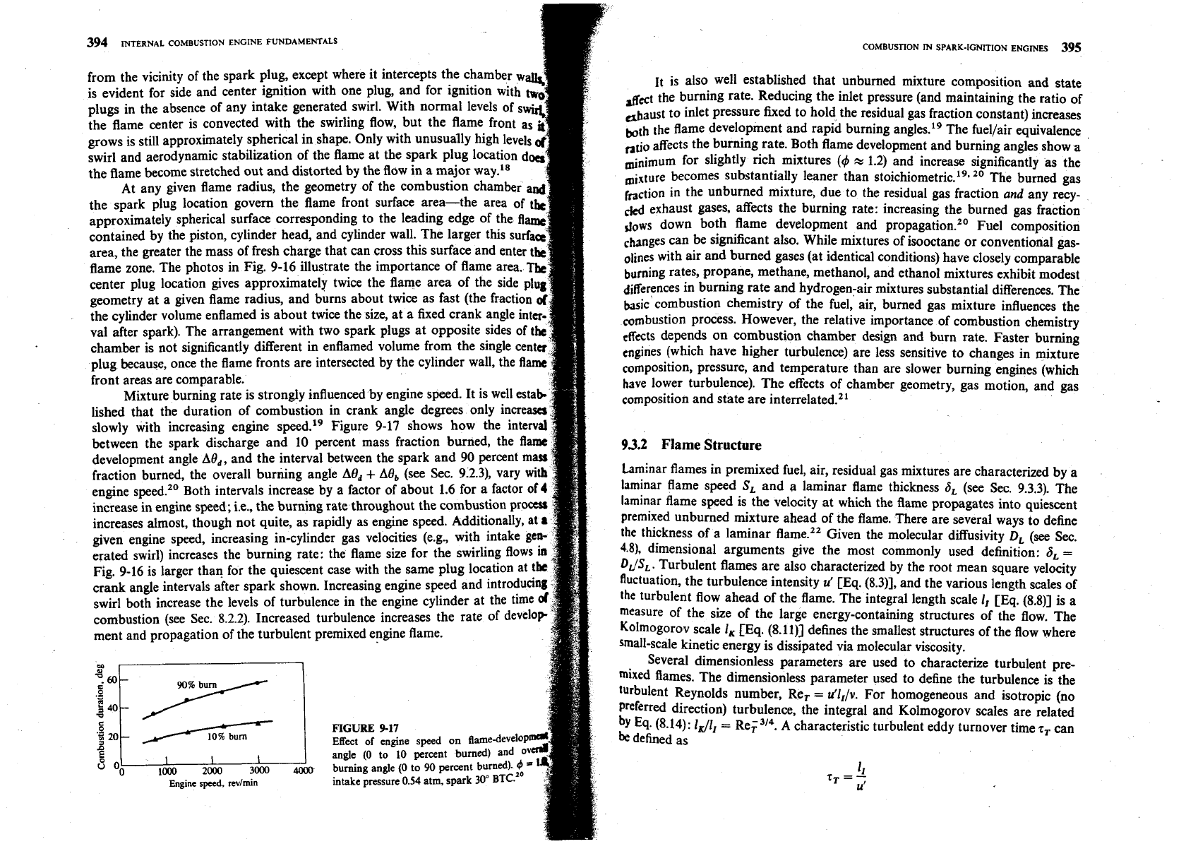
Mixture burning rate is strongly influenced by engine speed. It is well esta
lished that the duration of combustion in crank angle degrees only incre
slowly with increasing engine speed.19 Figure 9-17 shows how the in
between the spark discharge and 10 percent mass fraction burned, the
development angle
Ad,,
and the interval between the spark and 90 percent
mass
fraction burned, the overall burning angle
Ad,
+
Ad,
(see Sec. 9.2.3
engine speed." Both intervals increase by a factor of about 1.6 for a
increase in engine speed; i.e., the burning rate throughout the combustion pr
increases almost, though not quite, as rapidly as engine speed. Additionally,
at
given engine speed, increasing in-cylinder gas velocities (e.g., with intake ge
erated swirl) increases the burning rate: the flame size for the swirling flows
Fig. 9-16 is larger than for the quiescent case with the same plug location at t
crank angle intervals after spark shown. Increasing engine speed and introducing
swirl both increase the levels of turbulence in the engine cylinder at the time
combustion (see Sec. 8.2.2). Increased turbulence increases the rate of develo
ment and propagation of the turbulent premixed engine flame.
FIGURE
9-17
n
Effect of engine speed on flame-deve
angle
(0
to
10
percent burned) and
2&3
3&
4000
burning angle
(0
to
90
percent burn&
Engine
speed,
revlmn
intake pressure
0.54
atm, spark
30"
BTC.
COMBUSTION lN SPARK-IGNITION ENGlNES
395
11
is also well established that unburned mixture composition and state
the burning rate. Reducing the inlet pressure (and maintaining the ratio of
daust
to inlet pressure fixed to hold the residual gas fraction constant) increases
both the flame development and rapid burning angles.'' The fuellair equivalence
,,tio the burning rate. Both flame development and burning angles show
a
minimum for slightly rich mixtures
(4
x
1.2) and increase significantly as the
becomes substantially leaner than stoi~hiometric.'~~
20
The burned gas
friction
in the unburned mixture, due to the residual gas fraction
and
any recy-
gases, affects the burning rate: increasing the burned gas fraction
dews
down both flame development and pr~pagation.'~ Fuel composition
~bnges can be significant also. While mixtures of isooctane or conventional gas-
oline~ with air and burned gases (at identical conditions) have closely comparable
burning rates, propane, methane, methanol, and ethanol mixtures exhibit modest
diKerences in burning rate and hydrogen-air mixtures substantial differences. The
bjsic combustion chemistry of the fuel, air, burned gas mixture influences the
combustion process. However, the relative importance of combustion chemistry
effects depends on combustion chamber design and burn rate. Faster burning
engines (which have higher turbulence) are less sensitive to changes in mixture
composition, pressure, and temperature than are slower burning engines (which
have lower turbulence). The effects of chamber geometry, gas motion, and gas
composition and state are
interrelated.21
93.2
Flame Structure
Laminar flames in premixed fuel, air, residual gas mixtures are characterized by a
laminar flame speed
SL
and a laminar flame thickness
6,
(see
Sec.
9.3.3). The
laminar flame speed is the velocity at which the flame propagates into quiescent
premixed unburned mixture ahead of the flame. There are several ways to define
the thickness of a laminar flame." Given the molecular diffusivity
DL
(see Sec.
4.8),
dimensional arguments give the most commonly used definition:
6,
=
D
JSL.
Turbulent flames are also characterized by the root mean square velocity
fluctuation, the turbulence intensity
u'
[Eq. (8.3)], and the various length scales of
the
turbulent flow ahead of the flame. The integral length scale 1, [Eq. (841 is a
measure of the size of the large energy-containing structures of the flow. The
Kolmogorov scale 1, [Eq. (8.11)] defines the smallest structures of the flow where
small-scale kinetic energy is dissipated via molecular viscosity.
Several dimensionless parameters are used to characterize turbulent pre-
mixed flames. The dimensionless parameter used to define the turbulence is the
turbulent Reynolds number, Re,
=
ullI/v.
For homogeneous and isotropic (no
Preferred direction) turbulence, the integral and Kolmogorov scales are related
by
Eq. (8.14):
I&
=
Re;". A characteristic turbulent eddy turnover time
7,
can
be
defined as
396
mERNAL
COMBUSTION
ENGINE
FUNDAMENTALS
A characteristic chemical reaction time is the residence time in a laminar flame:
6,
r,
=
-
SL
The ratio of the characteristic eddy turnover time to the laminar burning time
b
called the
Damkohler number:
Da
=
'.
=
($I($)
=L
It is an inverse measure of the influence of the turbulent flow on the chemid
processes occurring in the flame. Other ratios are of interest. The ratio
6J,
is
measure of the stretch or local distortion to which a laminar flame is subjected
b
the turbulent flow. Unless
1,/6,
9
1 the concept of a localized flame region
little significance. The ratio
ut/SL
is a measure of the relative strength of
t~rbulence.~~
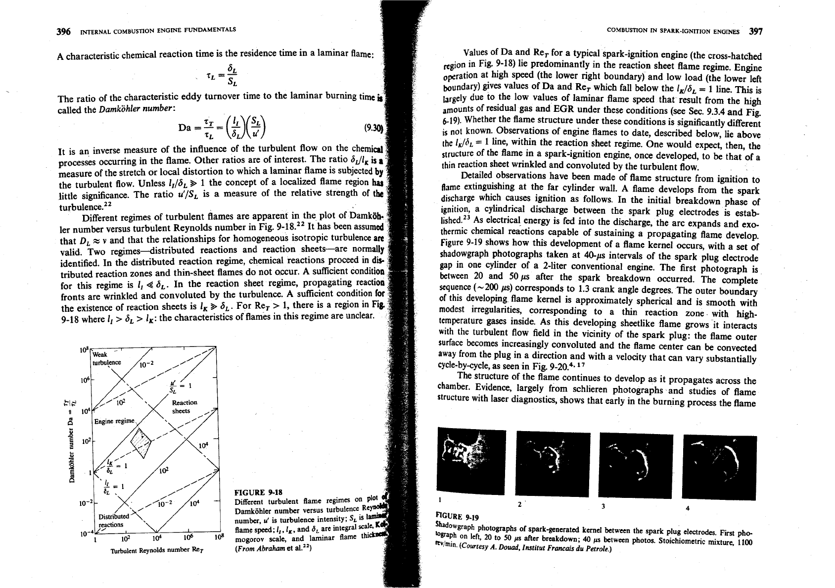
Different regimes of turbulent flames are apparent in the plot of Damk
ler number versus turbulent Reynolds number in Fig. 9-18.22 It has been
that
DL
z
v
and that the relationships for homogeneous isotropic turbu
valid. Two regimes--distributed reactions and reaction sheets-are norm
identified. In the distributed reaction regime, chemical reactions proceed in
d
tributed reaction zones and thin-sheet flames do not occur. A sufficient condit
for this regime is
I,
4
6,.
In the reaction sheet regime, propagating react
fronts are wrinkled and convoluted by the turbulence. A sufficient condition
the existence of reaction sheets is
I,
%
6,.
For Re,
>
1, there is a region in
Fi
9-18 where
I,
>
6,
>
lK:
the characteristics of flames in this regime are unclear.
FIGURE
9-18
Different turbulent Bame regimes
Damkohler number versus turbulence
number,
u'
is turbulence intensity;
SL
flame speed;
I,,
I,,
and
6,
are integral
1
l@
lo4
lo6 lo'
mogorov scale, and laminar flame
Turbulent Reynolds
number
R~T
(From Abraham
et a1.")
COMBUSTION
IN
SPARK-IGNITION
ENGINES
397
Values of Da and Re, for a typical spark-ignition engine (the cross-hatched
Ngion in Fig. 9-18) lie predominantly in the reaction sheet flame regime. Engine
,Fration at high speed (the lower right boundary) and low load (the lower left
boundary) gives values of Da and Re, which fall below the
IJ6,
=
1 line. This is
hrgely due to the low values of laminar flame speed that result from the high
mounts of residual gas and
EGR
under these conditions (see Sec. 9.3.4 and Fig.
6-19).
Whether the flame structure under these conditions is significantly different
is
not known. Observations of engine flames to date, described below, lie above
the
1
J6,
=
1
line, within the reaction sheet regime. One would expect, then, the
Structure of the flame in a spark-ignition engine, once developed, to be that of a
thin
reaction sheet wrinkled and convoluted by the turbulent flow.
Detailed observations have been made of flame structure from ignition to
flame extinguishing at the far cylinder wall. A flame develops from the spark
discharge which causes ignition as follows. In the initial breakdown phase of
ignition, a cylindrical discharge between the spark plug electrodes is estab-
li~hed.'~ As electrical energy is fed into the discharge, the arc expands and exo-
thermic chemical reactions capable of sustaining a propagating flame develop.
Figure
9-19
shows how this development of a flame kernel occurs, with a set of
shadowgraph photographs taken at 40-ps intervals of the spark plug electrode
gap
in one cylinder of a 2-liter conventional engine. The first photograph is
between 20 and Sops after the spark breakdown occurred. The complete
sequence (-200 ys) corresponds to 1.3 crank angle degrees. The outer boundary
of this developing flame kernel is approximately spherical and is smooth with
modest irregularities, corresponding to a thin reaction zone with high-
temperature gases inside. As this developing sheetlike flame grows it interacts
with
the turbulent flow field in the vicinity of the spark plug: the flame outer
surface becomes increasingly convoluted and the flame center can
be
convected
away from the plug in a direction and with a velocity that can vary substantially
cycle-by-cycle, as seen in Fig. 9-20?.
l7
The structure of the flame continues to develop as it propagates across the
chamber. Evidence, largely from schlieren photographs and studies of flame
structure with laser diagnostics, shows that early in the burning process the flame
CURE
9-19
sbd~~graph photographs of spark-generated kernel between the spark plug electrodes First
pho-
'"~aph on
left,
20
to
50
p
after breakdown;
40
ps
between photos. Stoichiometnc mixture,
1100
Avhin.
(Courtesy
A.
Douad, Institut Francais du Petrole.)
398
INTERNAL
COMBUSTION
ENGINE
FUNDAMENTALS
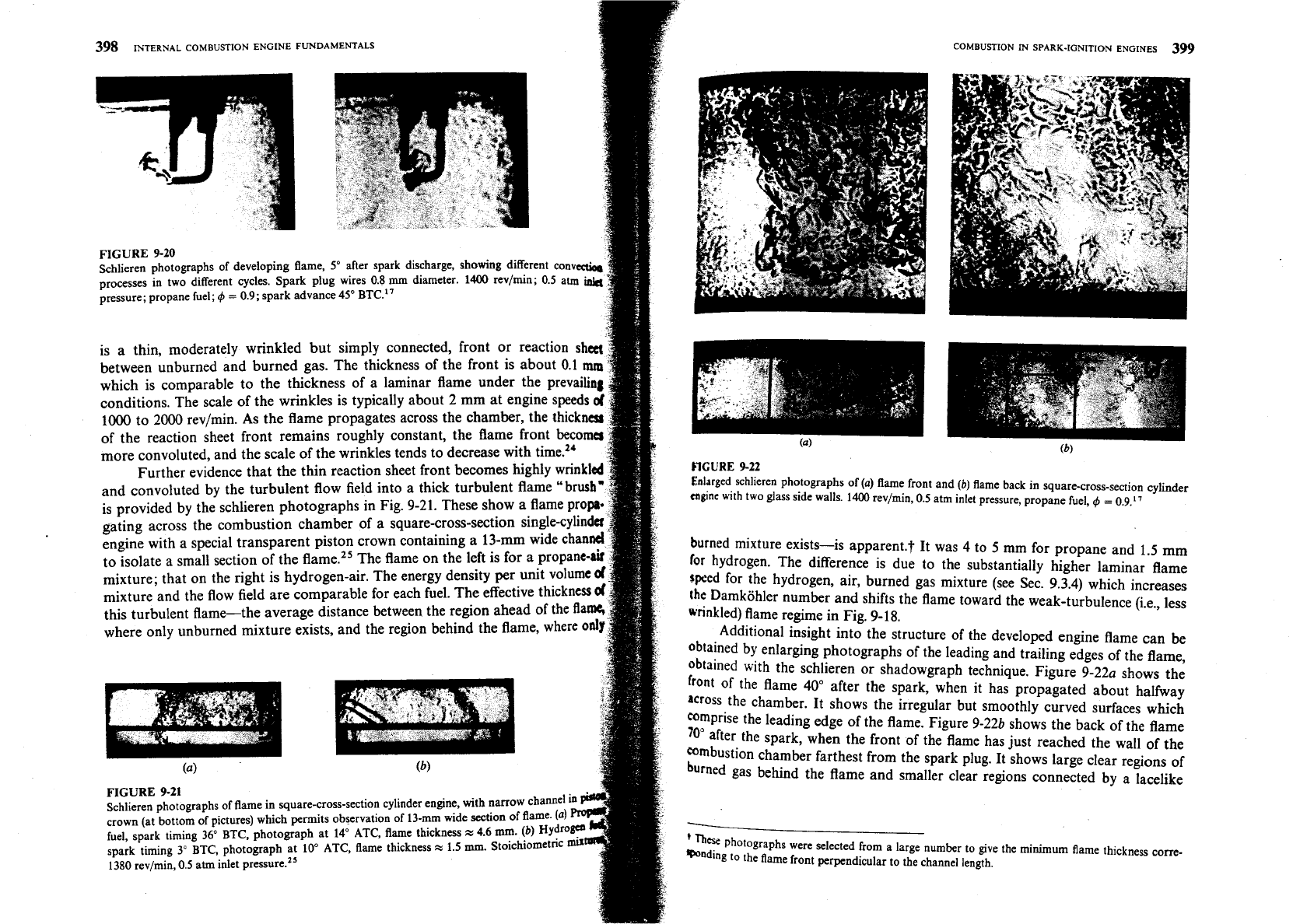
FIGURE
9-20
Schlieren photographs of developing flame, 5" after spark discharge, showing different con"
processes in two different cycles. Spark plug wires 0.8
rnm
diameter.
1400
rev/min; 0.5 atm
pressure; propane fuel;
4
=
0.9;
spark advance 45" BTC."
is a thin, moderately wrinkled but simply connected, front or reaction
sh
between unburned and burned gas. The thickness of the front is about 0.1
which is comparable to the thickness of a laminar flame under the prevaili
conditions. The scale of the wrinkles is typically about 2 mm at engine speeds
1000
to 2000 rev/min. As the flame propagates across the chamber, the thickn
of the reaction sheet front remains roughly constant, the flame front beco
more convoluted, and the scale of the wrinkles tends to decrease with time.24
Further evidence that the thin reaction sheet front becomes highly wink
and convoluted by the turbulent flow field into a thick turbulent flame
"
brus
is provided by the schlieren photographs in Fig. 9-21. These show a flame
gating across the combustion chamber of a square-cross-section single-
engine with a special transparent piston crown containing a
13-mm
wide
to isolate a small section of the flame." The flame on the left is for a propane-
mixture; that on the right is hydrogen-air. The energy density per unit volume
mixture and the flow field are comparable for each fuel. The effective thick
this turbulent flame-the average distance between the region ahead of the
where only unburned mixture exists, and the region behind the flame, where
0
(4
FIGURE
9-21
Schlieren photographs of flame in square-cross-section cylinder engine, with narro
crown (at bottom of pictures) which permits observation of 13-mm wide section
0
fuel, spark timing
36"
BTC, photograph at
14"
ATC, flame thickness
z
4.6
mm.
spark timing 3" BTC, photograph at 10' ATC, flame thickness
z
1.5
mm.
Stoic
1380
rev/min, 0.5 atm inlet press~re.~'
COMBUSTION IN SPARK-IGNITION ENGINES
399
FIGURE
9-22
Enlrrged schlieren photographs of
(a)
flame front and
(b)
flame back in square-cross-section cylinder
mginc with two glass side walls. 1400 rev/min, 0.5 atm inlet pressure, propane fuel,
4
=
0.9.17
burned mixture exists-is apparent.? It was 4 to
5
mm for propane and 1.5 mm
for
hydrogen. The difference is due to the substantially higher laminar flame
speed for the hydrogen, air, burned gas mixture (see Sec. 9.3.4) which increases
[he
Damkohler number and shifts the flame toward the weak-turbulence (i.e., less
winkled) flame regime in Fig. 9-18.
Additional insight into the structure of the developed engine flame can be
obtained by enlarging photographs of the leading and trailing edges of the flame,
obtained with the schlieren or shadowgraph technique. Figure 9-22a shows the
front of the flame 40' after the spark, when
it
has propagated about halfway
across the chamber. It shows the irregular but smoothly curved surfaces which
Wmprise the leading edge of the flame. Figure 9-226 shows the back of the flame
70'
after the spark, when the front of the flame has just reached the wall of the
mmbustion chamber farthest from the spark plug. It shows large clear regions of
burned gas behind the flame and smaller clear regions connected by a lacelike
-
'
Th.
photographs were selected from a large number to give the minimum flame thickness corre-
Wndink! to the flame front perpendicular to the channel length.
400
INTERNAL
COMBUSTION
ENGME FLJNDAMENTALS
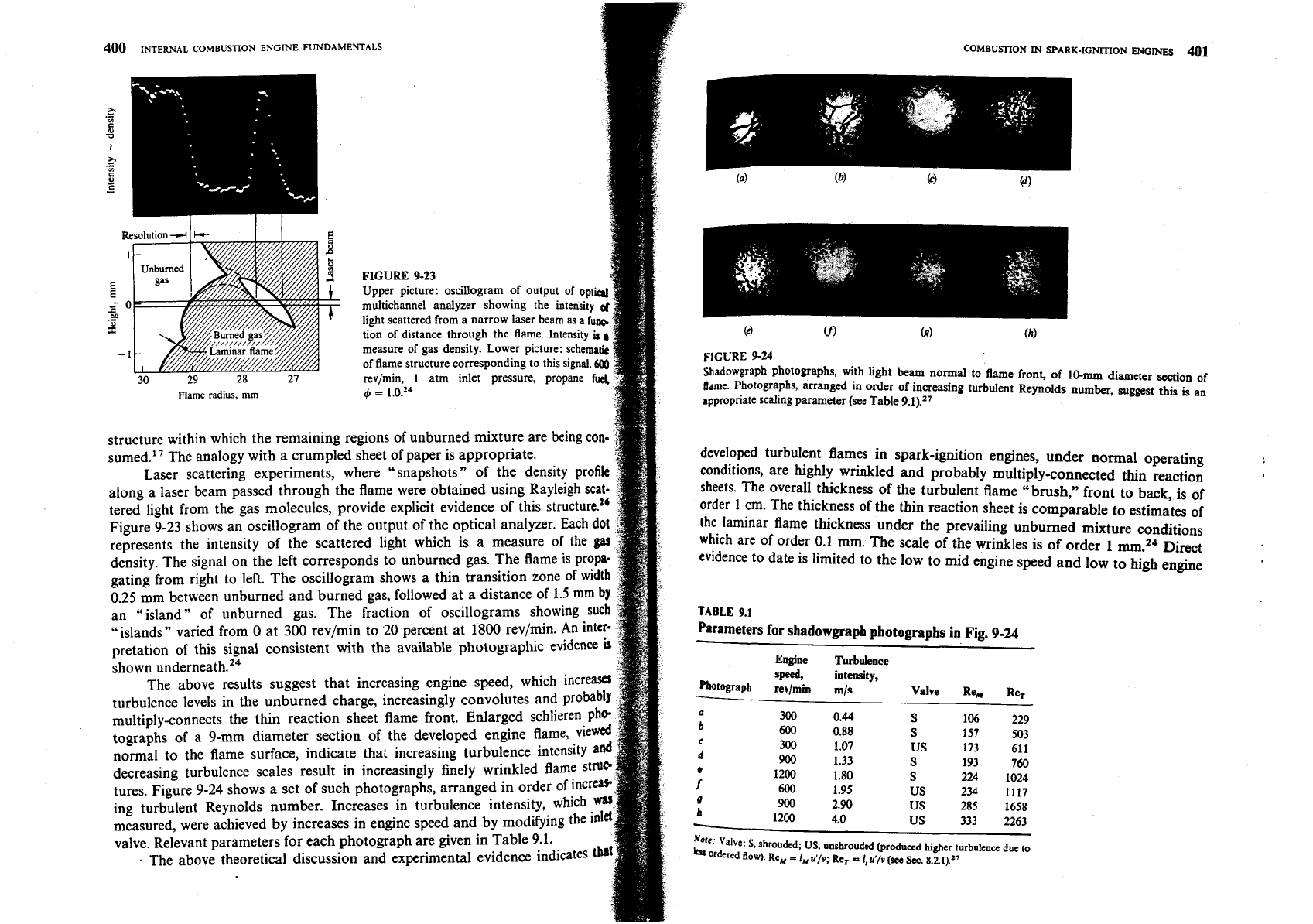
FIGURE
9-23
Upper picture: oscillogram of output of opt
multichannel analyzer showing the intensity
light scattered from a narrow laser
beam
as
a tu
tion of distance through the flame. Intensity
it
measure of gas density. Lower picture: schema
of flame structure corresponding to this signal.
30
29
28
27
revjmin,
1
atm inlet pressure, propane
Flame radius,
mm
4
=
1.0.~~
structure within which the remaining regions of unburned mixture are being con
sumed." The analogy with a crumpled sheet of paper is appropriate.
Laser scattering experiments, where "snapshots" of the density profit
along a laser beam passed through the flame were obtained using Rayleigh scat
tered light from the gas molecules, provide explicit evidence of this structure."
Figure 9-23 shows an oscillogram of the output of the optical analyzer. Each do
represents the intensity of the scattered light which is a. measure of the
g
density. The signal on the left corresponds to unburned gas. The flame is
gating from right to left. The oscillogram shows a thin transition zone
o
0.25
mm between unburned and burned gas, followed at a distance of
1.5
an "island" of unburned gas. The fraction of oscillograms showing
sue
"islands" varied from
0
at 300 revlmin to
20
percent at 1800 revlmin. An
int
pretation of this signal consistent with the available photographic evidence
shown ~nderneath.'~
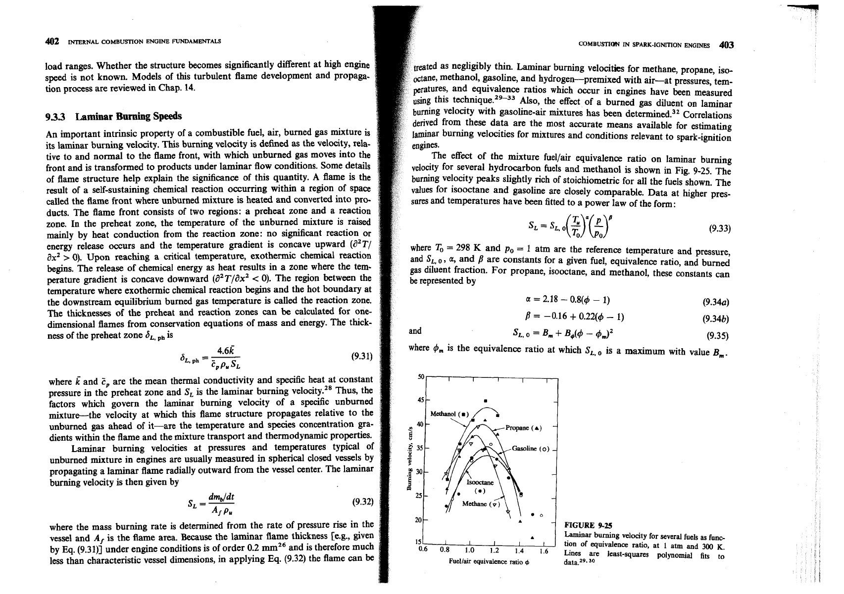
The above results suggest that increasing engine speed, which incre
turbulence levels in the unburned charge, increasingly convolutes and
p
multiply-connects the thin reaction sheet flame front. Enlarged schlieren
tographs of
a
9-mm diameter section of the developed engine flame,
vi
normal to the flame surface, indicate that increasing turbulence intensity a
decreasing turbulence scales result in increasingly finely wrinkled flame
St
tures. Figure 9-24 shows a set of such photographs, arranged in order of incr
ing turbulent Reynolds number. Increases in turbulence intensity, which
measured, were achieved by increases in engine speed and by modifying the in
valve. Relevant parameters for each photograph are given in Table 9.1.
The above theoretical discussion and experimental evidence indicates
COMBUSTION
IN
SPARK-IGNITION
ENGINES
41
flCURE
9-24
shadowgraph photographs, with light
beam
normal to flame front, of
1Gmm
diameter section of
flame. photographs, arranged in order of increasing turbulent Reynolds number, suggest this is an
jppropriate scaling parameter
(see
Table
9.1).17
developed turbulent flames in spark-ignition engines, under normal operating
conditions, are highly wrinkled and probably multiply-connected thin reaction
sheets. The overall thickness of the turbulent flame
"brush," front to back, is of
order
1
cm.
The thickness of the thin reaction sheet is comparable to estimates of
the laminar flame thickness under the prevailing unburned mixture conditions
which are of order 0.1 mm. The scale of the wrinkles is
of
order 1 mmZ4 Direct
evidence to date is limited to the low to mid engine speed and low to high engine
TABLE
9.1
Parameters for shadowgrapb photographs in Fig.
9-24
Engine Turbulence
speed,
intensity,
htograph
revlmin
m/s
Valve
Re,
Re,
o
300 0.44
S
106 229
b
600 0.88
S
157 503
c
300 1.07 US 173 611
d
900
1.33
S
193 760
1200
f
1.80 S
224 1024
600
1.95
US 234 1117
9
h
900
2.90
US 285 1658
1200 4.0
US 333 2263
Valve:
S
shrouded;
US,
unshrouded (produced higher turbulence due
to
km
Ordered flow). Re,
=
I,u'/v;
Re,
=
I,U'/Y
(see
Sec.
8.21).27
load ranges. Whether the structure becomes significantly different at high engine
speed is not known. Models of this turbulent flame development and propaga-
tion process are reviewed in Chap.
14.
933
Laminar
Burning
Speeds
An important intrinsic property of a combustible fuel, air, burned gas mixture is
its laminar burning velocity. This burning velocity is defined as the velocity, rela-
tive to and normal to the flame front, with which unburned gas moves into the
front and is transformed to products under laminar flow conditions. Some details
of flame structure help explain the significance of this quantity. A flame is the
result of a self-sustaining chemical reaction occumng within a region of space
called the flame front where unburned mixture is heated and converted into pro-
ducts. The flame front consists of two regions: a preheat zone and a reaction
zone. In the preheat zone, the temperature of the unburned mixture is raised
mainly by heat conduction from the reaction zone: no significant reaction or
energy release occurs and the temperature gradient is concave upward
(d2T/
ax2
>
0).
Upon reaching a critical temperature, exothermic chemical reaction
begins. The release of chemical energy as heat results in a zone where the tem-
perature gradient is concave downward (a2T/ax2
<
0). The region between the
temperature where exothermic chemical reaction begins and the hot boundary at
the downstream equilibrium burned gas temperature is called the reaction zone.
The thicknesses of the preheat and reaction zones can
be
calculated for one-
dimensional flames from conservation equations of mass and energy. The thick-
ness of the preheat zone
6,.
,,
is
where
and
2,
are the mean thermal conductivity and specific heat at constant
pressure
in
the preheat zone and
S,
is the laminar burning velocity." Thus, the
factors which govern the laminar burning velocity of
a
specific unburned
mixturethe velocity at which this flame structure propagates relative to the
unburned gas ahead of it-are the temperature and species concentration gra-
dients within the flame and the mixture transport and thermodynamic properties.
Laminar burning velocities at pressures and temperatures typical of
unburned mixture in engines are usually measured in spherical closed vessels by
propagating a laminar flame radially outward from the vessel center. The laminar
burning velocity is then given by
dm,/dt
SL
=
-
(9.32)
A,
PU
where the mass burning rate is determined from the rate of pressure rise in the
vessel and
Af
is the flame area. Because the laminar flame thickness [e.g., given
by Eq. (9.3111 under engine conditions is of order 0.2 and is therefore much
less than characteristic vessel dimensions, in applying Eq. (9.32) the flame can
be
COMBUSTION
IN
SPARK-IGNITION
ENGINES
403
eated as negligibly thin. Laminar burning velocities for methane, propane, iso-
tane, methanol, gasoline, and hydrogen-premixed with air-at pressures, tem-
peratures, and equivalence ratios which occur in engines have been measured
using this te~hnique.~'-~~ Also, the effect of a burned gas diluent on laminar
burning velocity with gasoline-air mixtures has been deter~nined.~' Correlations
derived from these data are the most accurate means available for estimating
laminar burning velocities for mixtures and conditions relevant to spark-ignition
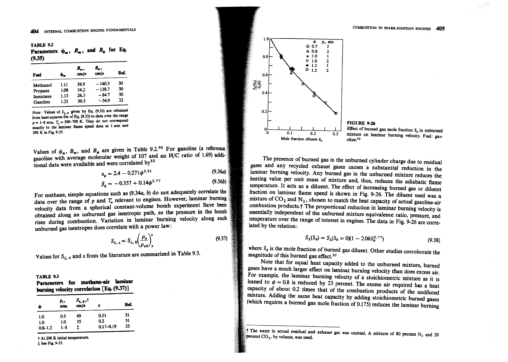
The effect of the mixture fuellair equivalence ratio on laminar burning
for several hydrocarbon fuels and methanol is shown in Fig. 9-25. The
burning velocity peaks slightly rich of stoichiometric for all the fuels shown. The
~alues for isooctane and gasoline are closely comparable. Data at higher pres-
sures and temperatures have been fitted to a power law of the form:
where
To
=
298
K
and
po
=
1 atm are the reference temperature and pressure,
and
SL,
o,
a, and
B
are constants for a given fuel, equivalence ratio, and burned
gas diluent fraction. For propane, isooctane, and methanol, these constants can
be represented by
F
p=
-0.16
+
0.22(4
-
1)
I
(9.34b)
and
St,
o
=
Bm
f
B&$
-
43'
(9.35)
where
t$,,,
is the equivalence ratio at which
S,,
,,
is a maximum with value
Bm.
!
t
FIGURE
9-25
A
Laminar burning velocity for several fuels as funo
I5
I I
I
I
I
tion of equivalence ratio, at
1
atm and
UK)
K.
0.6 0.8 1.0 1.2
1.4
1.6
Lines are least-squares polynomial fits to
Fuellair
equivalence
ratio
$
data.".
TABLE
9.2
Parameters
+-,
B,,
and
B,
for
Eq.
B,,
B,,
Fuel
+
cm/s
em/s
Ref.
Methanol
1.11
36.9
-
140.5
30
.
-.-
.An"
3,-,
Propane
Isooctane
Gasoline
Note:
Values
from
least-squ
of
S,,
given
by
Eq.
(9.35)
arc
obtained
arm
fits
of
Eq.
(9.33)
to
data
over
the
range
Values of
4,,,
B,,,
,
and
B1
are given in Table
0
7
30
For
@soline la reference
r
gasoline with average molecular weight of
107
~USU
-.
....".-
tional data were available and were correlated by3'
a,
=
2.4
-
0.27143.51
(9.36a)
For methane, simple equations such as
(9.34~
b)
do not adequately correlate
the
data over the range of
p
and
T
relevant to engines. However, laminar burning
velocity data from a spherical constant-volum.
WUW
obtained along an unburned gas isentropic path,
as
the pressure in
rises during combustion. Variation in laminar burning velocity
L--=
----
unburned gas isentropes does correlate with a power law:
S,,
.
=
s,
o(~)=
Puo
s
Values for
SL,
and
E
from the literature are summarized in Table
9.3.
TABLE
9.3
Parameters
for
methane&
laminar
burning
velocity
correlation
m.
(93711
nave
the
alnn~
L
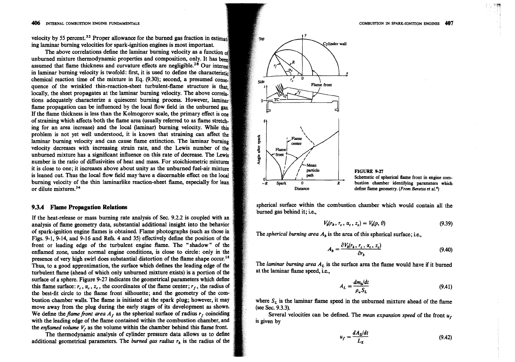
FIGURE
9-26
0
Effect
of burned gas mole fraction
P,
in unburned
0
Mole
0.1
fraction
diluent
0.2
fb
~iiine.~~
0.3
mixture on laminar burning velocity. Fuel: gas-
The presence of burned gas in the unburned cylinder charge due to residual
gases and any recycled exhaust gases causes a substantial reduction in the
laminar burning velocity. Any burned gas in the unburned mixture reduces the
heating value per unit mass of mixture and, thus, reduces the adiabatic
flame
temperature. It acts as a diluent. The effect of increasing burned gas or diluent
fraction on laminar flame speed is shown in Fig. 9-26. The diluent used was a
mixture of
CO,
and
N2
,
chosen to match the heat capacity of actual gasoline-air
combustion products.f The proportional reduction in laminar burning velocity is
essentially independent of the unburned mixture equivalence ratio, pressure, and
temperature over the range of interest in engines. The data in Fig.
9-26
are corre-
lated by the relation:
where
&
is the mole fraction of burned
gas
diluent. Other studies corroborate the
magnitude of this burned gas effect.3Z
Note that for equal heat capacity added to the unburned mixture, burned
gases have a much larger effect on laminar burning velocity than does excess air.
For example, the laminar burning velocity of a stoichiometric mixture as it is
leaned to
9
=
0.8
is reduced by
23
percent. The excess air required has a heat
capacity of about
0.2
times that of the combustion products of the undiluted
mixture. Adding the same heat capacity by adding stoichiometric burned gmes
(which requires a burned gas mole fraction of
0.175)
reduces the laminar burning
f
The
water
in
actual residual and exhaust
gas
was omitted.
A
mixture of
80
percent
N.
nnd
3n
percent
CO,
,
by volume, was
used.
t
At
298
K
initial
temperature.
$
Sa
Fig.
9-25.
COMBUSTION
IN
SPARK-IGNITION ENGINES
407
406
INTERNAL
COMBUSTION
ENGINE
FUNDAMENTALS
velocity by 55 percent.32 Proper allowance for the burned gas fraction in
ing laminar burning velocities for spark-ignition engines is most important.
The above correlations define the laminar burning velocity as a functi
unburned mixture thermodynamic properties and composition, only. It has
assumed that flame thickness and curvature effects are negligible.28 Our
in laminar burning velocity is twofold: first, it is used to define the char
chemical reaction time of the mixture in Eq. (9.30); second, a presumed c
quence of the wrinkled thin-reaction-sheet turbulent-flame structure is
locally, the sheet propagates at the laminar burning velocity. The above corre
tions adequately characterize a quiescent burning process. Ho
flame propagation can be influenced by the local flow field
If the flame thickness is less than the Kolmogorov scale, the
of straining which affects both the flame area (usually referred to as
ing for an area increase) and the local (laminar) burning velocity. While this
problem
is
not yet well understood, it is known that straining can affect the
laminar burning velocity and can cause flame extinction. The laminar burning
velocity decreases with increasing strain rate, and the Lewis number of the
unburned mixture has a significant influence on this rate of decrease. The Lewis
number is the ratio of diffusivities of heat and mass. For stoichiometric mixtures
it is close to one; it increases above about unity as the unburned fuel-air mixture
FIGURE
9-27
is leaned out. Thus the local flow field may 'have a discernable effect on the local
Schematic
of
spherical he
front
in
engine
corn-
burning velocity of the thin laminarlike reaction-sheet flame, especially for lean
-R
spark
0
bustion
chamber
identifying
parameters
which
or dilute mixtures.34
Distance
define flame geometry.
(From
Beretta
et
a13
93.4
Flame
Propagation Relations
spherical surface within the combustion chamber which would contain all the
burned gas behind it; i.e.,
If the heat-release or mass burning rate analysis of Sec. 9.2.2 is coupled with an
analysis of flame geometry data, substantial additional insight into the behavior
arb, rc,
a,, 2,)
=
UP,
(9.39)
of spark-ignition engine flames is obtained. Flame photographs (such as those in
The spherical burning area A, is the area of this spherical surface; i.e.,
Figs. 9-1,9-14, and 9-16 and Refs.
4
and 35) effectively define the position of the
front or leading edge of the turbulent engine flame. The "shadow" of the
A,
=
a
Urb
,
rc
9
ac
,
2,)
enflamed zone, under normal engine conditions, is close to circle: only in the
arb
(9.40)
presence of very high swirl does substantial distortion of the flame shape occur.'"
Thus, to a good approximation, the surface which dehes the leading edge of the
The laminar burning area
A, is the surface area the flame would have
if
it burned
turbulent flame (ahead of which only unburned mixture exists) is a portion of the
at the laminar flame speed, i.e.,
surface of a sphere. Figure 9-27 indicates the geometrical parameters which define
this flame surface:
rc
,
ac
,
z,
,
the coordinates of the flame center; rf
,
the radius of
dmddt
A,
=
-
(9.41)
the best-fit circle to the flame front silhouette; and the geometry of the corn-
P,
SL
bustion chamber walls. The flame
is
initiated at the spark plug; however, it may
speed in the unburned mixture ahead of the flame
move away from the plug during the early stages of its development
as
shown,
We dehe theframefront area Af as the spherical surface of radius rf coinciding
Several velocities can be defined. The mean expansion speed of the front uf
with the leading edge of the flame contained within the combustion chamber, and
the
enframed volume Vf as the volume within the chamber behind this flame front.
The thermodynamic analysis of cylinder pressure data allows
us
to define
uf
=
-
dAs/dt
additional geometrical parameters. The burned gas radius rb is the radius of the
(9.42)
Ls
408
INTERNAL
COMBUSTION
ENGIN6
WAMENTALS
where
A,
is the "shadow" area enclosed by the
"
best-fit" circle through the!
leading edge of the flame and
is the arc length within the chamber of this
"
best-fit
"
circle. The
mean expansion
speed
of the
burned gas u,
is
This derivative is taken with the piston position fixed since only burned volume
changes due to combustion are of interest. The
burnina sneed
Sl
is defined bv
The
mean gas speed
just ahead of the flame front
u,
is
u,
=
Ub
-
Sb
Note that combining Eqs. (9.41) and (9.44) gives the relation
Sb
A,
=
SL
A,
Also, it follows from Eqs. (9.29), (9.43), and (9.44) that
As
x,
and
y,
+
0,
ub/Sb
approaches the expansion ratio
p Jp,
.
As
x,
and
y,
-r
1,
,
u$Sb
approaches unity.
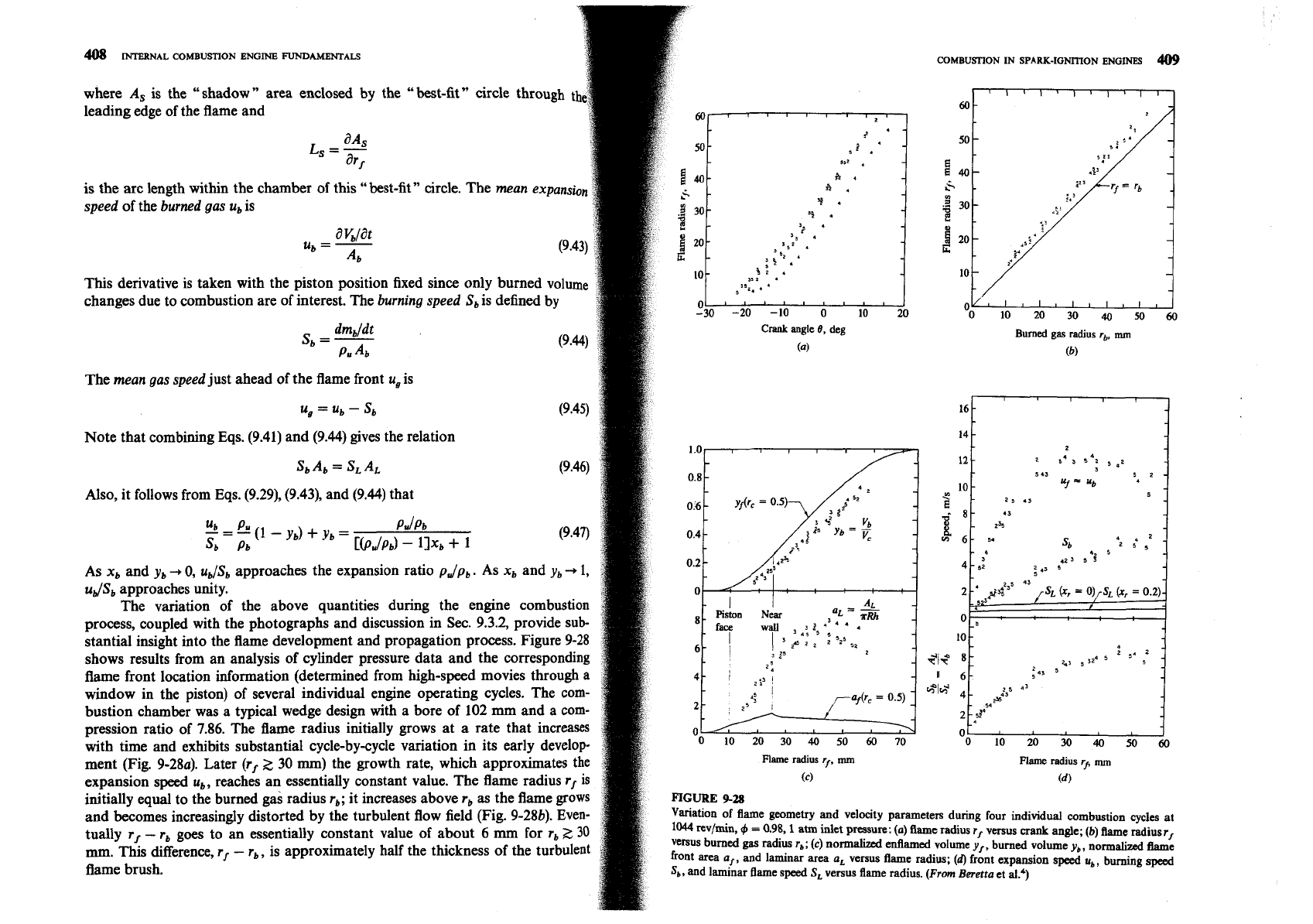
The variation of the above quantities during the engine combustion
shows results from an analysis of cylinder pressure data and the corresponding
flame front location information (determined from high-speed movies through
a
window in the piston) of several individual engine operating cycles. The com-
bustion chamber was a typical wedge design with a bore of 102 mm and a com-
~ression ratio of
7.86.
The flame radius initially grows at a rate that increases
tually
rf
-
r,
goes to an essentially constant value of about
6
mm
for
r,
>,
30
mm.
This difference,
r,
-
r,,
is approximately half the thickness of the turbulent
:
410
INTERNAL
COMBU~ON
ENGINE
FUNDAMENTALS
COMBU~ON
m
SPARK-IGNITION
ENGINES
41
1
3.5
Normalized enflamed and burned volumes, and flame front area and
laminar burning area, are shown in Fig. 9-28c. Volumes are normalized by the
-
3.0
cylinder volume, and areas by
nRh,
where
h
is the average clearance height and
R
the cylinder radius. Discontinuities occur in the flame area
a,
at the points where
the flame front contacts first the piston face and then the near cylinder wall. The
laminar area A, is initially close to the flame area A, and then increases rapidly
as the flame grows beyond 10 mm in radius. During the rapid burning com-
bustion phase
Cv,
2
0.2) the value of y, is significantly greater than y,. During
this phase, the laminar area exceeds the flame area by almost an order of magni.
tude. These observations indicate the existence of substantial pockets of
unburned mixture behind the leading edge of the
flame.4
The ratio of the volume of the unburned mixture within the turbulent flame
zone (V,
-
h)
to the reaction-sheet area within the flame zone (AL
-
A,) defines
342
346
350 354 358
362
a characteristic length
Crank
angle,
deg
V'
-
v,
IT
=
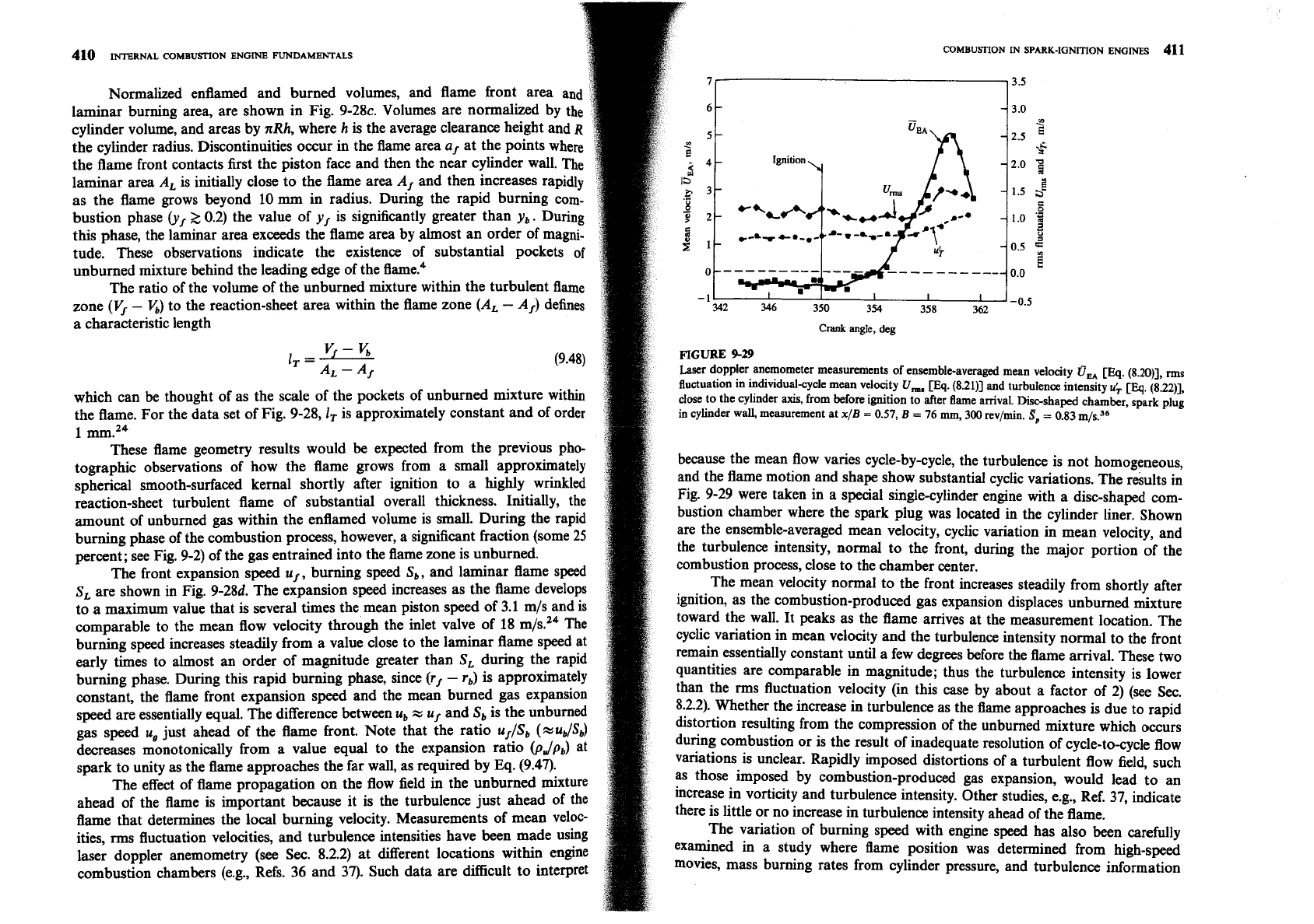
FIGURE
9-29
A,
-
4
Laser doppler anemometer measurements of ensemble-averaged mean velocity
a,,
[EQ.
(8.2011, ms
fluctuation in individual-cycle mean velocity
U,,
pq.
(8.21)] and turbulence intensity
u;
CEq.
(8.22)],
which can be thought of as the scale of the pockets of unburned mixture within
close to the cylinder
axis,
from before ignition to after flame amval. Disc-shaped chamber, spark plug
the flame. For the data set of Fig. 9-28,1T is approximately constant and of order
in
cylinder wall, measurement at
x/B
=
0.57,
B
=
76
ma
300
rev/min.
$p
=
0.83 rnls.36
1 mmZ4
These flame geometry results would be expected from the previous pho-
tographic observations of how the flame grows from a small approximately
because the mean flow varies cycle-by-cycle, the turbulence is not homogeneous,
spherical smooth-surfaced kernal shortly after ignition to a highly wrinkled
and the flame motion and shape show substantial cyclic variations. The
results in
reaction-sheet turbulent flame of substantial overall thickness. Initially, the
Fig. 9-29 were taken in a special single-cylinder engine with a disc-shaped com-
amount of unburned gas within the enflamed volume is small. During the rapid
bustion chamber where the spark plug was located in the cylinder liner. Shown
burning phase of the combustion process, however, a significant fraction (some
25
are the ensemble-averaged mean velocity, cyclic variation in mean velocity, and
percent; see Fig. 9-2) of the gas entrained into the flame zone is unburned.
the turbulence intensity, normal to the front, during the major portion of the
The front expansion speed
u,, burning speed S,, and laminar flame speed
combustion process, close to the chamber center.
S, are shown in Fig. 9-281. The expansion speed increases as the flame develops
The mean velocity normal to the front increases steadily from shortly after
to a maximum value that is several times the mean piston speed of 3.1
m/s and is
ignition, as the combustion-produced gas expansion displaces unburned mixture
comparable to the mean flow velocity through the inlet valve of 18 mbZ4 The
toward the wall. It peaks as the flame arrives at the measurement location. The
burning speed increases steadily from a value close to the laminar flame speed at
cyclic variation in mean velocity and the turbulence intensity normal to the front
early times to almost an order of magnitude greater than S, during the rapid
remain essentially constant until a few degrees before the flame arrival. These two
burning phase. During this rapid burning phase, since (r,
-
r,) is approximately
quantities are comparable in magnitude; thus the turbulence intensity is lower
constant, the flame front expansion speed and the mean burned gas expansion
than the rms fluctuation velocity (in this case by about a factor of 2) (see
Sec.
speed are essentially equal. The difference between u,
x
u, and S, is the unburned
8.2.2). Whether the increase in turbulence as the flame approaches is due to rapid
gas speed
u, just ahead of the flame front. Note that the ratio u//Sb (%udSb)
distortion resulting from the compression of the unburned mixture which occurs
decreases monotonically from a value equal to the expansion ratio
@,,/pb)
at
during combustion or is the result of inadequate resolution of cycle-to-cycle flow
spark to unity as the flame approaches the far wall, as required by Eq. (9.47).
variations is unclear. Rapidly imposed distortions of a turbulent flow field, such
The effect of flame propagation on the flow field in the unburned mixture
as those imposed by combustion-produced gas expansion, would lead to an
ahead of the flame is important because it is the turbulence just ahead of the
increase in vorticity and turbulence intensity. Other studies, e.g., Ref. 37, indicate
flame that determines the local burning velocity. Measurements of mean veloc-
there is little or no increase in turbulence intensity ahead of the flame.
ities, rms fluctuation velocities, and turbulence intensities have been made using
The variation of burning speed with engine speed has also been carefully
laser doppler anemometry (see
Sec.
8.2.2) at different locations within engine
examined in a study where flame position was determined from high-speed
combustion chambers
(e.g., Refs. 36 and 37). Such data are difficult to interpret
movies, mass burning rates from cylinder pressure, and turbulence information