Hennessy John L., Patterson David A. Computer Architecture
Подождите немного. Документ загружается.


402 ■ Chapter Six Storage Systems
the past, manufacturers listed the seek of this distance to offer a consistent basis
for comparison. (Today they calculate the “average” by timing all seeks and
dividing by the number.) Assuming (incorrectly) that seek time is linear in dis-
tance, and using the manufacturer’s reported minimum and “average” seek times,
a common technique to predict seek time is
Time
seek
= Time
minimum
+
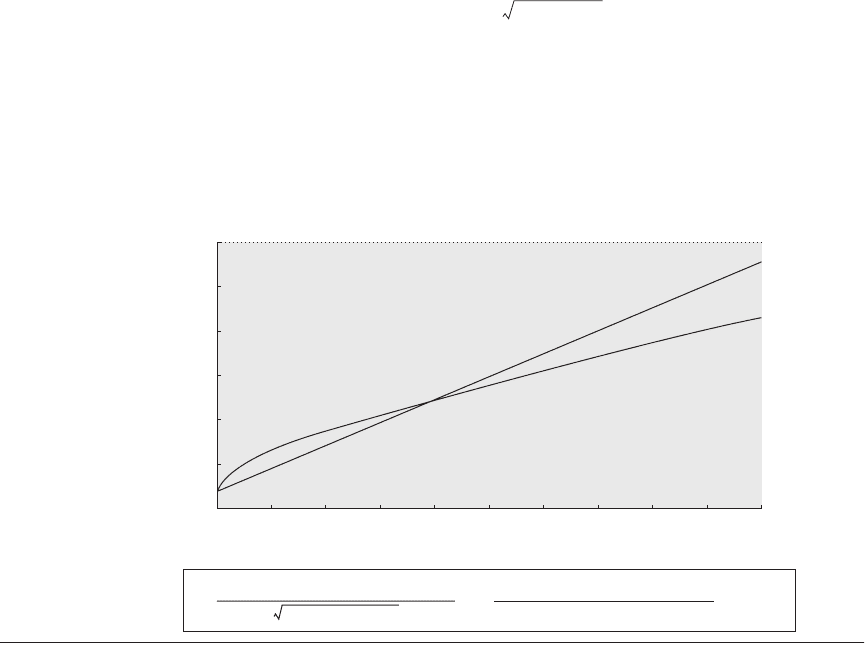
The fallacy concerning seek time is twofold. First, seek time is not linear with
distance; the arm must accelerate to overcome inertia, reach its maximum travel-
ing speed, decelerate as it reaches the requested position, and then wait to allow
the arm to stop vibrating (settle time). Moreover, sometimes the arm must pause
to control vibrations. For disks with more than 200 cylinders, Chen and Lee
[1995] modeled the seek distance as
where a, b, and c are selected for a particular disk so that this formula will match
the quoted times for Distance = 1, Distance = max, and Distance = 1/3 max. Fig-
ure 6.23 plots this equation versus the fallacy equation. Unlike the first equation,
the square root of the distance reflects acceleration and deceleration.
The second problem is that the average in the product specification would
only be true if there were no locality to disk activity. Fortunately, there is both
Figure 6.23 Seek time versus seek distance for sophisticated model versus naive model. Chen and Lee [1995]
found that the equations shown above for parameters a, b, and c worked well for several disks.
Distance
Distance
average
-----------------------------------
Time
average
Time
minimum
–()×
Seek time Distance()a Distance 1–× b Distance 1–()× c++=
30
25
20
15
10
5
Access time (ms)
0
Seek distance
0
a =
3 × Number of cylinders
250 500 750 1000 1250 1500
Naive seek formula
New seek formula
1750 2000
2250
2500
– 10 × Time
min
+ 15 × Time
avg
– 5 × Time
max
b =
3 × Number of cylinders
7 × Time
min
– 15 × Time
avg
+ 8 × Time
max
c =
Time
min

6.10 Concluding Remarks ■ 403
temporal and spatial locality (see page C-2 in Appendix C). For example,
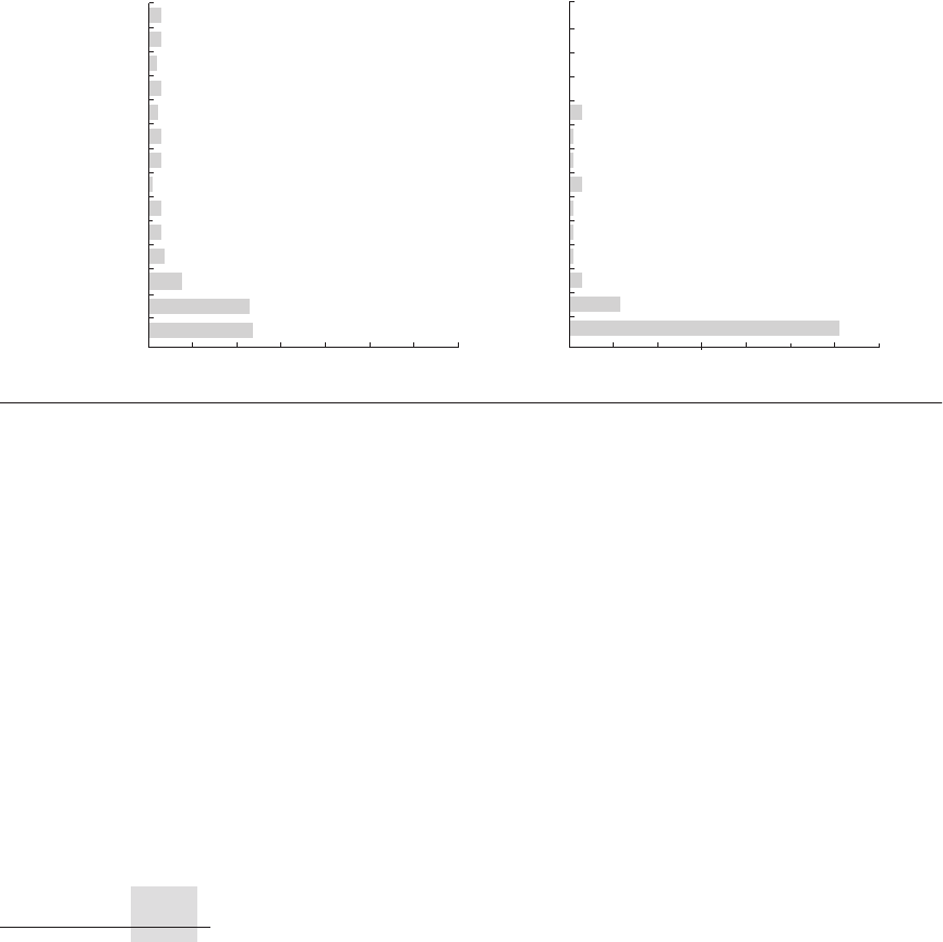
Figure 6.24 shows sample measurements of seek distances for two workloads: a
UNIX time-sharing workload and a business-processing workload. Notice the
high percentage of disk accesses to the same cylinder, labeled distance 0 in the
graphs, in both workloads. Thus, this fallacy couldn’t be more misleading.
Storage is one of those technologies that we tend to take for granted. And yet, if
we look at the true status of things today, storage is king. One can even argue that
servers, which have become commodities, are now becoming peripheral to
storage devices. Driving that point home are some estimates from IBM, which
expects storage sales to surpass server sales in the next two years.
Michael Vizard
editor in chief, Infoworld, August 11, 2001
Figure 6.24 Sample measurements of seek distances for two systems. The measurements on the left were taken
on a UNIX time-sharing system. The measurements on the right were taken from a business-processing application
in which the disk seek activity was scheduled to improve throughput. Seek distance of 0 means the access was made
to the same cylinder. The rest of the numbers show the collective percentage for distances between numbers on the
y-axis. For example, 11% for the bar labeled 16 in the business graph means that the percentage of seeks between 1
and 16 cylinders was 11%. The UNIX measurements stopped at 200 of the 1000 cylinders, but this captured 85% of
the accesses. The business measurements tracked all 816 cylinders of the disks. The only seek distances with 1% or
greater of the seeks that are not in the graph are 224 with 4%, and 304, 336, 512, and 624, each having 1%. This total
is 94%, with the difference being small but nonzero distances in other categories. Measurements courtesy of Dave
Anderson of Seagate.
0%
10%
Percentage of seeks (UNIX time-sharing workload)
23%
8%
4%
20%
40%
30% 50% 60% 70%
24%
3%
3%
1%
3%
3%
3%
3%
3%
2%
2%
0%
10%
Percentage of seeks (business workload)
Seek
distance
Seek
distance
11%
20%
40%
30% 50% 60% 70%
61%
3%
0%
3%
0%
0%
1%
1%
1%
1%
1%
3%
0%
195
180
165
150
135
120
105
90
75
60
45
30
15
0
208
192
176
160
144
128
112
96
80
64
48
32
16
0
6.10 Concluding Remarks

404 ■ Chapter Six Storage Systems
As their value is becoming increasingly evident, storage systems have become
the target of innovation and investment.
The challenge for storage systems today is dependability and maintainability.
Not only do users want to be sure their data are never lost (reliability), applica-
tions today increasingly demand that the data are always available to access
(availability). Despite improvements in hardware and software reliability and
fault tolerance, the awkwardness of maintaining such systems is a problem both
for cost and for availability. A widely mentioned statistic is that customers spend
$6 to $8 operating a storage system for every $1 of purchase price. When depend-
ability is attacked by having many redundant copies at a higher level of the sys-
tem—such as for search—then very large systems can be sensitive to the price-
performance of the storage components.
Today, challenges in storage dependability and maintainability dominate the
challenges of I/O.
Section K.7 on the companion CD covers the development of storage devices and
techniques, including who invented disks, the story behind RAID, and the history
of operating systems and databases. References for further reading are included.
Case Study 1: Deconstructing a Disk
Concepts illustrated by this case study
■ Performance Characteristics
■ Microbenchmarks
The internals of a storage system tend to be hidden behind a simple interface, that
of a linear array of blocks. There are many advantages to having a common inter-
face for all storage systems: an operating system can use any storage system
without modification, and yet the storage system is free to innovate behind this
interface. For example, a single disk can map its internal <sector, track, surface>
geometry to the linear array in whatever way achieves the best performance; sim-
ilarly, a multidisk RAID system can map the blocks on any number of disks to
this same linear array. However, this fixed interface has a number of disadvan-
tages as well; in particular, the operating system is not able to perform some per-
formance, reliability, and security optimizations without knowing the precise
layout of its blocks inside the underlying storage system.
6.11 Historical Perspective and References
Case Studies with Exercises by Andrea C. Arpaci-Dusseau
and Remzi H. Arpaci-Dusseau
Case Studies with Exercises by Andrea C. Arpaci-Dusseau and Remzi H. Arpaci-Dusseau ■ 405
In this case study, we will explore how software can be used to uncover the
internal structure of a storage system hidden behind a block-based interface. The
basic idea is to fingerprint the storage system: by running a well-defined work-
load on top of the storage system and measuring the amount of time required for
different requests, one is able to infer a surprising amount of detail about the
underlying system.
The Skippy algorithm, from work by Nisha Talagala and colleagues at U.C.
Berkeley, uncovers the parameters of a single disk. The key is to factor out disk
rotational effects by making consecutive seeks to individual sectors with
addresses that differ by a linearly increasing amount (increasing by 1, 2, 3, and so
forth). Thus, the basic algorithm skips through the disk, increasing the distance of
the seek by one sector before every write, and outputs the distance and time for
each write. The raw device interface is used to avoid file system optimizations.
The SECTOR SIZE is set equal to the minimum amount of data that can be read at
once from the disk (e.g., 512 bytes). (Skippy is described in more detail in Tala-
gala et al. [1999].)
fd = open("raw disk device");
for (i = 0; i < measurements; i++) {
begin_time = gettime();
lseek(fd, i*SECTOR_SIZE, SEEK_CUR);
write(fd, buffer, SECTOR_SIZE);
interval_time = gettime() -begin_time;
printf("Stride: %d Time: %d\n", i, interval_time);
}
close(fd);
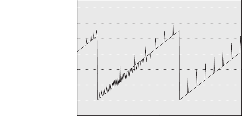
By graphing the time required for each write as a function of the seek dis-
tance, one can infer the minimal transfer time (with no seek or rotational latency),
head switch time, cylinder switch time, rotational latency, and the number of
heads in the disk. A typical graph will have four distinct lines, each with the same
slope, but with different offsets. The highest and lowest lines correspond to
requests that incur different amounts of rotational delay, but no cylinder or head
switch costs; the difference between these two lines reveals the rotational latency
of the disk. The second lowest line corresponds to requests that incur a head
switch (in addition to increasing amounts of rotational delay). Finally, the third
line corresponds to requests that incur a cylinder switch (in addition to rotational
delay).
6.1 [10/10/10/10/10] <6.2> The results of running Skippy are shown for a mock disk
(Disk Alpha) in Figure 6.25.
a. [10] <6.2> What is the minimal transfer time?
b. [10] <6.2> What is the rotational latency?
c. [10] <6.2> What is the head switch time?

406 ■ Chapter Six Storage Systems
d. [10] <6.2> What is the cylinder switch time?
e. [10] <6.2> What is the number of disk heads?
6.2 [25] <6.2> Draw an approximation of the graph that would result from running
Skippy on Disk Beta, a disk with the following parameters:
■ Minimal transfer time: 2.0 ms
■ Rotational latency: 6.0 ms
■ Head switch time: 1.0 ms
■ Cylinder switch time: 1.5 ms
■ Number of disk heads: 4
■ Sectors per track: 100
6.3 [10/10/10/10/10/10/10] <6.2> Implement and run the Skippy algorithm on a disk
drive of your choosing.
a. [10] <6.2> Graph the results of running Skippy. Report the manufacturer and
model of your disk.
b. [10] <6.2> What is the minimal transfer time?
c. [10] <6.2> What is the rotational latency?
d. [10] <6.2> What is the head switch time?
e. [10] <6.2> What is the cylinder switch time?
Figure 6.25 Results from running Skippy on Disk Alpha.
Time (ms)
14
12
10
0
6
4
2
8
0
Distance (sectors)
300250200150100
50
Case Studies with Exercises by Andrea C. Arpaci-Dusseau and Remzi H. Arpaci-Dusseau ■ 407
f. [10] <6.2> What is the number of disk heads?
g. [10] <6.2> Do the results of running Skippy on a real disk differ in any quali-
tative way from that of the mock disk?
Case Study 2: Deconstructing a Disk Array
Concepts illustrated by this case study
■ Performance Characteristics
■ Microbenchmarks
The Shear algorithm, from work by Timothy Denehy and colleagues at the Uni-
versity of Wisconsin [Denehy et al. 2004], uncovers the parameters of a RAID
system. The basic idea is to generate a workload of requests to the RAID array
and time those requests; by observing which sets of requests take longer, one can
infer which blocks are allocated to the same disk.
We define RAID properties as follows. Data is allocated to disks in the RAID
at the block level, where a block is the minimal unit of data that the file system
reads or writes from the storage system; thus, block size is known by the file sys-
tem and the fingerprinting software. A chunk is a set of blocks that is allocated
contiguously within a disk. A stripe is a set of chunks across each of D data disks.
Finally, a pattern is the minimum sequence of data blocks such that block offset i
within the pattern is always located on disk j.
6.4 [20/20] <6.2> One can uncover the pattern size with the following code. The
code accesses the raw device to avoid file system optimizations. The key to all of
the Shear algorithms is to use random requests to avoid triggering any of the
prefetch or caching mechanisms within the RAID or within individual disks. The
basic idea of this code sequence is to access N random blocks at a fixed interval p
within the RAID array and to measure the completion time of each interval.
for (p = BLOCKSIZE; p <= testsize; p += BLOCKSIZE) {
for (i = 0; i < N; i++) {
request[i] = random()*p;
}
begin_time = gettime();
issues all request[N] to raw device in parallel;
wait for all request[N] to complete;
interval_time = gettime() - begin_time;
printf("PatternSize: %d Time: %d\n", p,
interval_time);
}
If you run this code on a RAID array and plot the measured time for the N
requests as a function of p, then you will see that the time is highest when all N

408 ■ Chapter Six Storage Systems
requests fall on the same disk; thus, the value of p with the highest time corre-
sponds to the pattern size of the RAID.
a. [20] <6.2> Figure 6.26 shows the results of running the pattern size algorithm
on an unknown RAID system.
■ What is the pattern size of this storage system?
■ What do the measured times of 0.4, 0.8, and 1.6 seconds correspond to in
this storage system?
■ If this is a RAID 0 array, then how many disks are present?
■ If this is a RAID 0 array, then what is the chunk size?
b. [20] <6.2> Draw the graph that would result from running this Shear code on
a storage system with the following characteristics:
■ Number of requests: N = 1000
■ Time for a random read on disk: 5 ms
■ RAID level: RAID 0
■ Number of disks: 4
■ Chunk size: 8 KB
6.5 [20/20] <6.2> One can uncover the chunk size with the following code. The basic
idea is to perform reads from N patterns chosen at random, but always at con-
trolled offsets, c and c – 1, within the pattern.
for (c = 0; c < patternsize; c += BLOCKSIZE) {
for (i = 0; i < N; i++) {
requestA[i] = random()*patternsize + c;
requestB[i] = random()*patternsize +
(c-1)%patternsize;
}
Figure 6.26 Results from running the pattern size algorithm of Shear on a mock storage system.
Time (s)
1.5
0
1.0
0.5
0.0
Pattern size assumed (KB)
256160 192 2241289664
32

Case Studies with Exercises by Andrea C. Arpaci-Dusseau and Remzi H. Arpaci-Dusseau ■ 409
begin_time = gettime();
issue all requestA[N] and requestB[N] to raw device
in parallel;
wait for requestA[N] and requestB[N] to complete;
interval_time = gettime() - begin_time;
printf("ChunkSize: %d Time: %d\n", c, interval_time);
}
If you run this code and plot the measured time as a function of c, then you will
see that the measured time is lowest when the requestA and requestB reads fall on
two different disks. Thus, the values of c with low times correspond to the chunk
boundaries between disks of the RAID.
a. [20] <6.2> Figure 6.27 shows the results of running the chunk size algorithm
on an unknown RAID system.
■ What is the chunk size of this storage system?
■ What do the measured times of 0.75 and 1.5 seconds correspond to in this
storage system?
b. [20] <6.2> Draw the graph that would result from running this Shear code on
a storage system with the following characteristics:
■ Number of requests: N = 1000
■ Time for a random read on disk: 5 ms
■ RAID level: RAID 0
■ Number of disks: 8
■ Chunk size: 12 KB
6.6 [10/10/10/10] <6.2> Finally, one can determine the layout of chunks to disks
with the following code. The basic idea is to select N random patterns, and to
exhaustively read together all pairwise combinations of the chunks within the
pattern.
Figure 6.27 Results from running the chunk size algorithm of Shear on a mock stor-
age system.
Time (s)
1.5
0
1.0
0.5
0.0
Boundary offset assumed (KB)
644832
16

410 ■ Chapter Six Storage Systems
for (a = 0; a < numchunks; a += chunksize) {
for (b = a; b < numchunks; b += chunksize) {
for (i = 0; i < N; i++) {
requestA[i] = random()*patternsize + a;
requestB[i] = random()*patternsize + b;
}
begin_time = gettime();
issue all requestA[N] and requestB[N] to raw device
in parallel;
wait for all requestA[N] and requestB[N] to
complete;
interval_time = gettime() - begin_time;
printf("A: %d B: %d Time: %d\n", a, b,
interval_time);
}
}
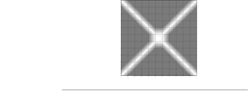
After running this code, you can report the measured time as a function of a and
b. The simplest way to graph this is to create a two-dimensional table with a and
b as the parameters, and the time scaled to a shaded value; we use darker shad-
ings for faster times and lighter shadings for slower times. Thus, a light shading
indicates that the two offsets of a and b within the pattern fall on the same disk.
Figure 6.28 shows the results of running the layout algorithm on a storage system
that is known to have a pattern size of 384 KB and a chunk size of 32 KB.
a. [20] <6.2> How many chunks are in a pattern?
b. [20] <6.2> Which chunks of each pattern appear to be allocated on the same
disks?
Figure 6.28 Results from running the layout algorithm of Shear on a mock storage
system.
Chunk
10
0
6
4
2
8
0
Chunk
108642

Case Studies with Exercises by Andrea C. Arpaci-Dusseau and Remzi H. Arpaci-Dusseau ■ 411
c. [20] <6.2> How many disks appear to be in this storage system?
d. [20] <6.2> Draw the likely layout of blocks across the disks.
6.7 [20] <6.2> Draw the graph that would result from running the layout algorithm
on the storage system shown in Figure 6.29. This storage system has 4 disks, a
chunk size of four 4 KB blocks (16 KB), and is using a RAID 5 Left-Asymmetric
layout.
Case Study 3: RAID Reconstruction
Concepts illustrated by this case study
■ RAID Systems
■ RAID Reconstruction
■ Mean Time to Failure (MTTF)
■ Mean Time until Data Loss (MTDL)
■ Performability
■ Double Failures
A RAID system ensures that data is not lost when a disk fails. Thus, one of the
key responsibilities of a RAID is to reconstruct the data that was on a disk when
it failed; this process is called reconstruction and is what you will explore in this
case study. You will consider both a RAID system that can tolerate one disk fail-
ure, and a RAID-DP, which can tolerate two disk failures.
Reconstruction is commonly performed in two different ways. In off-line
reconstruction, the RAID devotes all of its resources to performing reconstruc-
tion and does not service any requests from the workload. In on-line reconstruc-
tion, the RAID continues to service workload requests while performing the
Figure 6.29 A storage system with 4 disks, a chunk size of four 4 KB blocks, and
using a RAID 5 Left-Asymmetric layout. Two repetitions of the pattern are shown.
00 01 02 03 04 05 06 07 08 09 10 11 PPPP
12 13 14 15 16 17 18 19 PPPP20 21 22 23
24 25 26 27 PPPP28 29 30 31 32 33 34 35
PPPP36 37 38 39 40 41 42 43 44 45 46 47
48 49 50 51 52 53 54 55 56 57 58 59 PPPP
60 61 62 63 64 65 66 67 PPPP68 69 70 71
72 73 74 75 PPPP76 77 78 79 80 81 82 83
PPPP84 85 86 87 88 89 90 91 92 93 94 95
Parity: RAID 5 Left–Asymmetric, stripe = 16, pattern = 48
