Hearn E.J. Mechanics of Materials. Volume 1
Подождите немного. Документ загружается.

411.14
Strain Energy
213
deflection under the load is equal to the end deflection of either cantilever and given by
eqn. (1 1.19),
6,=-(%)b
5AG
6
L
or
6,=-
5AG
(wb)a
-
L
6
Wab
SAGL
6,
=
~
..
(11.23)
(e) Simply supported beam carrying uniformly distributed
load
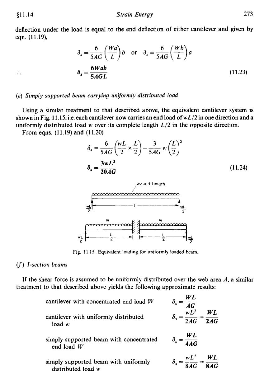
Using a similar treatment to that described above, the equivalent cantilever system is
shown in Fig. 11.15, i.e. each cantilever now carries an end load of wL/2 in one direction and a
uniformly distributed load
w
over its complete length L/2 in the opposite direction.
From eqns. (11.19) and (11.20)
3wL2
6,
=
~
20AG
w/unif
length
(11.24)
Fig.
11.15.
Equivalent loading
for
uniformly loaded beam.
(f)
1-section beams
If the shear force is assumed to be uniformly distributed over the web area A, a similar
treatment to that described above yields the following approximate results:
WL
6
=-
AG
cantilever with concentrated end load
W
cantilever with uniformly distributed
load
w
wL2
WL
2AG
==
6,
=
__
WL
6,
=
-
4AG
simply supported beam with concentrated
end load
W
wL2
WL
6,
=
__
~AG
=8AG
simply supported beam with uniformly
distributed load
w
274
Mechanics
of
Materials
411.14
In the above expressions the effect of the flanges has been neglected and it therefore follows
that the same formulae would apply for rectangular sections if it were assumed that the shear
stress is evenly distributed across the section. The result of
WL/AG
for the cantilever carrying
aconcentrated end load is then directly comparable to that obtained in eqn. (1 1.19) taking full
account of the variation of shear across the section, i.e.
6/5
(
WL/AG).
Since the shear strain
y
=
6/L
it follows that both the deflection and associated shear strain is underestimated by
20%
if the shear is assumed to
be
uniform.
(g) Shear dejlections at points other than loading points
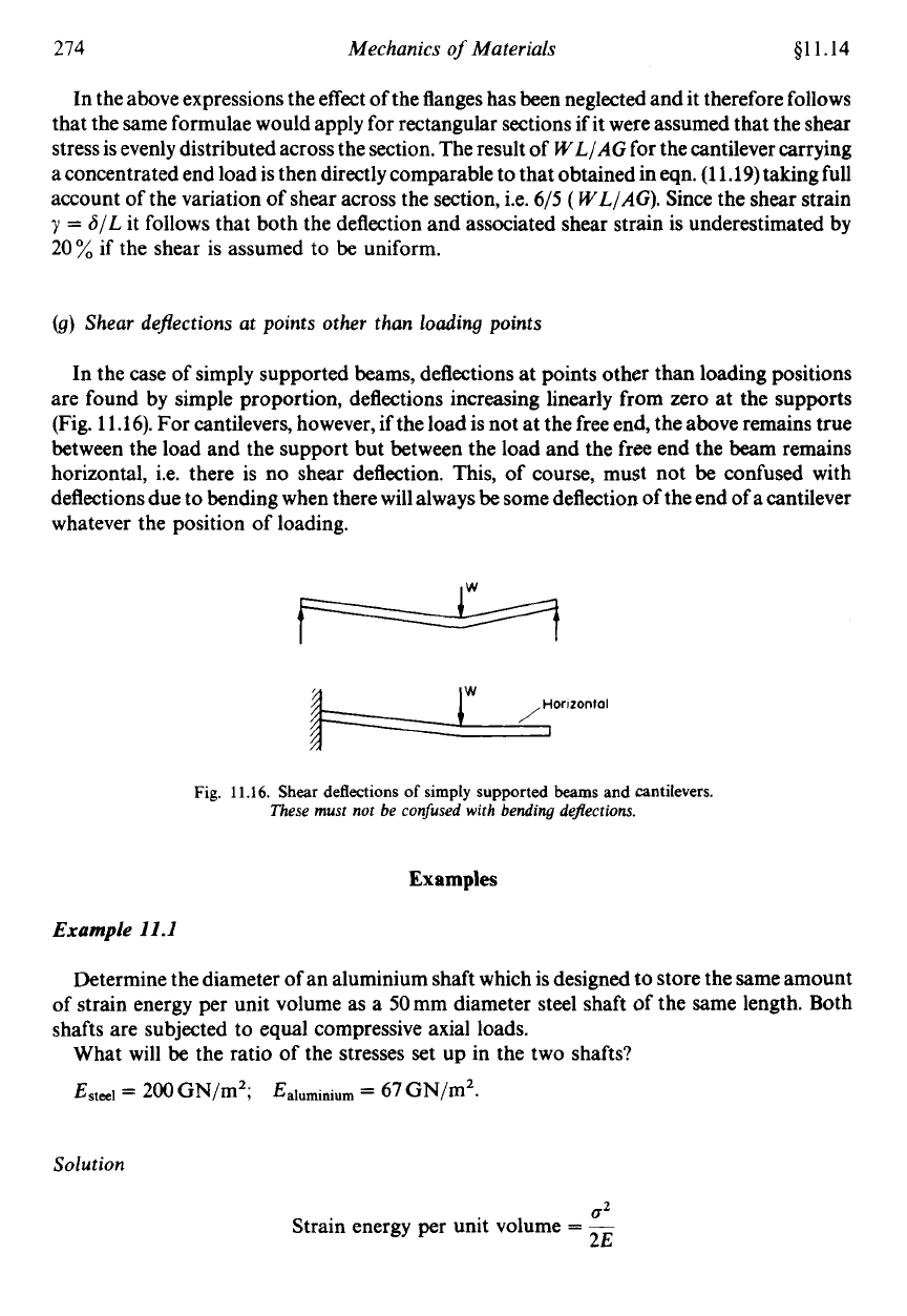
In the case of simply supported beams, deflections at points other than loading positions
are found by simple proportion, deflections increasing linearly from zero
at
the supports
(Fig. 11.16). For cantilevers, however, if the load is not at the free end, the above remains true
between the load and the support but between the load and the free end the beam remains
horizontal, Le. there is no shear deflection. This, of course, must not be confused with
deflections due to bending when there will always be some deflection of the end of a cantilever
whatever the position of loading.
Fig.
11.16.
Shear
deflections
of
simply supported
beams
and cantilevers.
These must not be confused with bending de$ections.
Examples
Example
11.1
Determine the diameter of an aluminium shaft which
is
designed
to
store the same amount
of strain energy per unit volume as a 50mm diameter steel shaft of the same length. Both
shafts are subjected to equal compressive axial loads.
What will be the ratio
of
the stresses
set
up
in the two shafts?
Esteel
=
200
GN/m2;
Ealuminium
=
67
GN/mZ.
Solution
02
Strain energy per unit volume
=
-
2E
Strain Energy
275
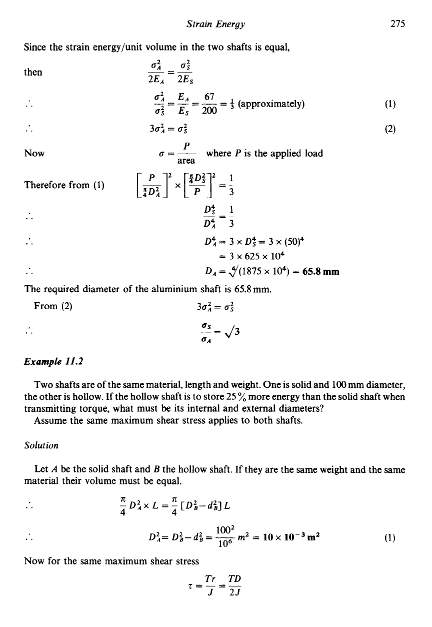
Since the strain energyjunit volume in the two shafts is equal,
then
Now
05
EA 67
-
=-=--
-
f
(approximately)
0%
Es
200
30;
=
a:
P
a=-
where
P
is the applied load
area
Therefore from (1)
Df
1
Dt
3
0;
=
3
x
Df
=
3
x
(50)4
DA
=
4/(1875
x
lo4)
=
65.8
mm
=-
-
..
..
=
3
x
625
x
104
..
The required diameter of the aluminium shaft is 65.8mm.
From
(2)
30:
=
a:
..
““43
aA
Example
11.2
Two shafts are of the same material, length and weight. One is solid and 100 mm diameter,
the other is hollow. If the hollow shaft is to store
25
%
more energy than the solid shaft when
transmitting torque, what must
be
its internal and external diameters?
Assume the same maximum shear stress applies to both shafts.
Solution
Let
A
be
the solid shaft and
B
the hollow shaft. If they are the same weight and the same
material their volume must
be
equal.
Now for the same maximum shear stress
Tr TD
J 25
T=-=-
276
Mechanics
of
Materials
i.e.
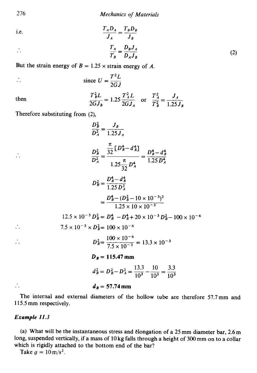
But the strain energy
of
B
=
1.25
x
strain energy
of
A.
then
T’,
JA
--
T;L
T;
L
-
1.25-
or
--
E&-
~GJA
Ti
1.25JB
Therefore substituting from
(2),
D;
JB
D’,
1.255,
=---
-
-
0;-
(0:-
10
x
10-3)2
-
1.25
x
io
10-3
12.5
x
lop3
0%
=
D;
-
D;+
20
x
Di-
100
x
..
7.5
x
10-3
x
~zg=
100
10-6
100
x
10-6
Dzg=
=
13.3
x
10-3
7.5
x
10-3
DB
=
115.47
mm
13.3
10 3.3
di=
Di-D’,
=
=-
io3
io3
103
..
dB
=
57.74
mm
115.5
mm respectively.
The internal and external diameters
of
the hollow tube are therefore 57.7mm and
Example
11.3
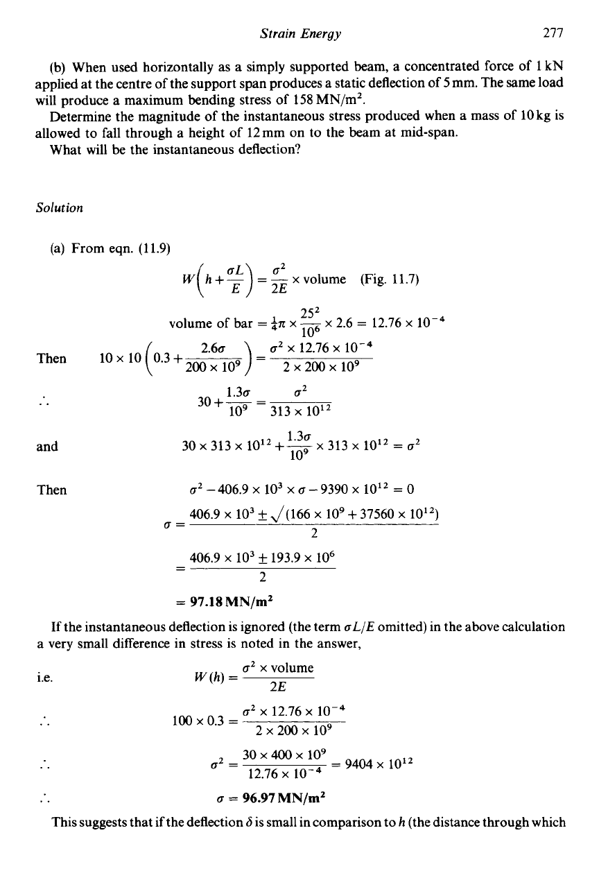
(a) What will be the instantaneous stress and elongation
of
a
25
mm diameter bar,
2.6
m
long, suspended vertically,
if
a mass of
10
kg falls through a height of
300
mm on to a collar
which is rigidly attached to the bottom end
of
the bar?
Take
g
=
10m/s2.
Strain
Energy
277
(b) When used horizontally as a simply supported beam, a concentrated force of
1
kN
applied at the centre of the support span produces a static deflection of
5
mm. The same load
will produce a maximum bending stress of
158
MN/m’.
Determine the magnitude of the instantaneous stress produced when a mass of
10
kg is
allowed to fall through a height of
12mm
on to the beam at mid-span.
What will be the instantaneous deflection?
Solution
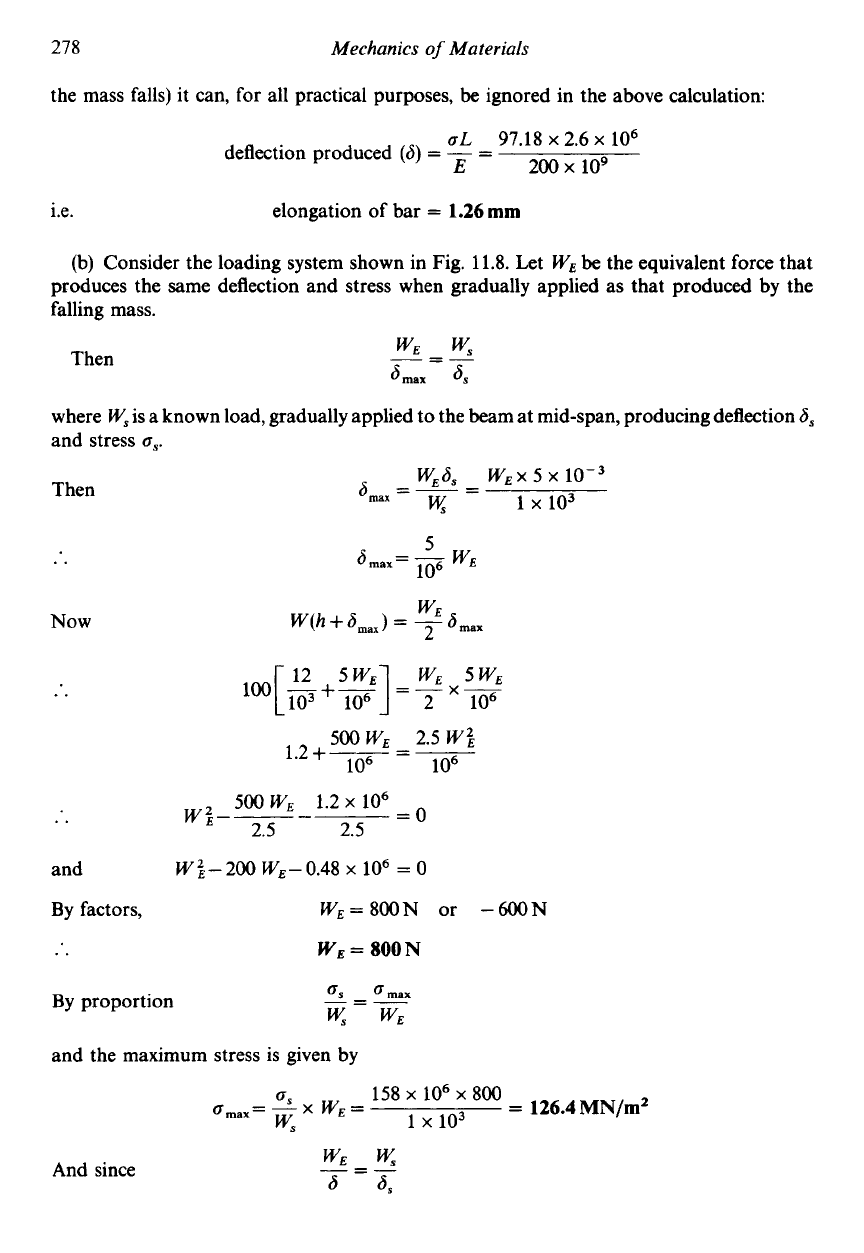
(a) From eqn.
(11.9)
w
h
+-
=
-
x
volume (Fig.
11.7)
( :)
;;
25’
lo6
volume of bar
=
in
x
~
x 2.6
=
12.76 x
O’
x 12.76
x
Then
10 x 10
1.30
O2
30+-
=
109
3i3x
1012
..
1.30
30
x
313
x
10”
f-
x
313
x
10”
=
O’
109
and
Then
u2
-
406.9
x
lo3
x
u
-
9390
x
10l2
=
0
406.9 x
lo3
f
J(166 x
lo9
+
37560 x
2
O=
406.9 x
lo3
f
193.9 x
lo6
2
-
-
=
97.18
MN/m2
If the instantaneous deflection is ignored (the term
aL/E
omitted) in the above calculation
a very small difference in stress is noted in the answer,
i.e.
O’
x
volume
2E
W
(h)
=
o2
x 12.76 x
lop4
..
100
x
0.3
=
2
x
200
x
109
30 400
109
..
02
=
=
9404
x
10”
12.76 x
..
o
=
96.97
MN/mZ
This suggests that if the deflection
6
is small in comparison to
h
(the distance through which
278
Mechanics
of
Materials
the mass falls) it can, for all practical purposes,
be
ignored in the above calculation:
aL
97.18
x
2.6
x
lo6
deflection produced
(6)
=
-
=
E
200
x
109
i.e. elongation of bar
=
1.26mm
(b)
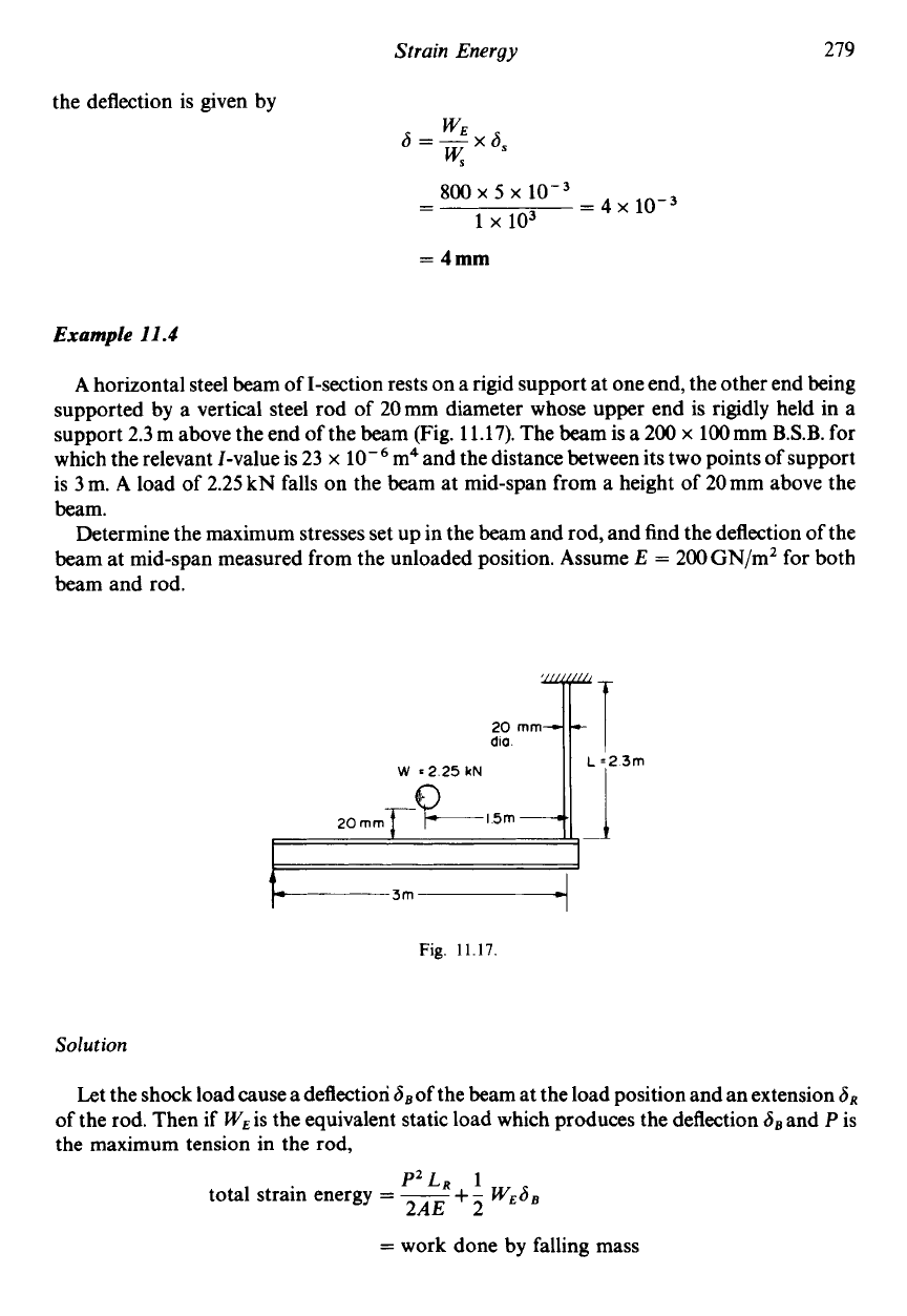
Consider the loading system shown in Fig. 11.8. Let
WE
be the equivalent force that
produces the same deflection and stress when gradually applied as that produced by the
falling mass.
Then
ws
6max
6s
-=-
where
W,
is a known load, gradually applied to the beam at mid-span, producing deflection
6,
and stress
a,.
Then
w~6,
WEX
5
x
a,=--
-
1
x
103
K
..
SOOWE
2.5
W’,
10 10.
1.2+-3-=-
By
factors, w~=800N or -6oN
..
WE
=
800N
By
proportion
6s
amax
-=-
WE
and the maximum stress is given by
And since
WE
-=-
6 6,
Strain
Energy
279
the deflection is given by
=
4
x
10-3
800
x
5
x
-
-
1
x
103
=
4mm
Example
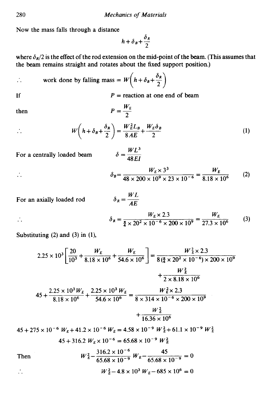
11.4
A horizontal steel beam of I-section rests on a rigid support at one end, the other end being
supported
by
a vertical steel rod
of
20mm diameter whose upper end is rigidly held in a
support
2.3
m above the end of the beam (Fig.
11.17).
The beam is
a
200
x
100
mm
B.S.B.
for
which the relevant I-value is
23
x
m4 and the distance between its two points of support
is
3
m. A load of
2.25
kN falls on the beam at mid-span from a height of
20
mm above the
beam.
Determine the maximum stresses set up in the beam and rod, and find the deflection of the
beam at mid-span measured from the unloaded position. Assume E
=
200
GN/m2 for both
beam and rod.
dio
W
=225kN
Fig.
11.17.
Solution
Let the shock load cause a deflection SBof the beam at the load position and an extension
SR
of
the rod. Then if
WE
is the equivalent static load which produces the deflection
SB
and
P
is
the maximum tension in the rod,
P2LR
1
2AE 2
total strain energy
=
-
+-
WES,
=
work done
by
falling mass
280
Mechanics
of
Materials
Now the mass falls through a distance
L
where 6R/2 is the effect of the rod extension on the mid-poin
the beam remains straight and rotates about the fixed support position.)
f
the beam. (This
.. work done by falling mass
=
W
If
P
=
reaction at one end of beam
then
WE
p=-
2
ssumes that
WL3
6=-
48 EI
For a centrally loaded beam
(2)
WEX 33
-
WE
48
x
200 x
lo9
x
23
x
-
8.18 x
lo6
6.q
=
WL
AE
6R
=
-
For an axially loaded rod
..
Substituting (2) and
(3)
in (l),
WE Wix2.3
2.25 x 10³
-+
[
:09
8.18 x
lo6
+
8
(4
x
202 x
x
200
x
lo9
w’,
2 x 8.18
x
lo6
+
W2
x
2.3
8 x 314
x
loW6
x 200
x
lo9
+
-
-
2.25 x 10³
wE
2.25
x
103
wE
45+ 8.18 x
lo6
+
54.6
x
lo6
w’,
16.36
x
lo6
45+275
x
WE+41.2 x WE
=
4.58
x
W’,+61.1 x W’,
45
+
316.2 WE x
=
65.68 x
low9
W’,
Then
316.2
x
45
65.68
x
65.68
x
low9
=
W’,- WE
-
..
W’,-4.8
x
lo3
WE-685
x
lo6
=
0
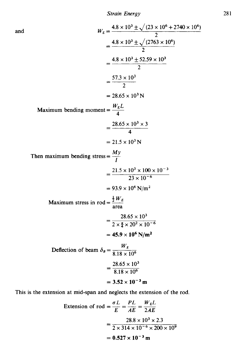
Strain Energy
28
1
and
4.8
x
lo3
f
J(23
x
lo6
+
2740
x
lo6)
2
WE
=
-
4.8
x
lo3
f
J(2763
x
lo6)
-
2
4.8
x
103 52.59
x
103
57.3
x
103
- -
2
- -
2
=
28.65
x
103N
WEL
Maximum bending moment
=
~
4
28.65
x
lo3
x
3
4
- -
=
21.5
x
103~
MY
Then maximum bending stress
=
__
I
21.5
x
103
x
io0
x
10-3
- -
23
x
=
93.9
x
lo6
N/m2
3
WE
Maximum stress in rod
=
-
area
28.65
x
lo3
- -
2
x
2
x
202
x
10-6
=
45.9
x
lo6
N/m’
WE
Deflection
of
beam
6
-
-
8.18
x
lo6
28.65
x
lo3
8.18
x
lo6
=
3.52
x
m
- -
This is the extension at mid-span and neglects the extension
of
the rod.
UL
PL WEL
Extension
of
rod
=
-
=
-
=
~
E AE 2AE
28.8
x
lo3
x
2.3
- -
2
x
314
x
10-6
x
200
x
109
=
0.527
x
m
282
Mechanics
of
Materials
Assuming, as stated earlier, that the beam remains straight and that the beam rotates about
the fixed end, then the effect
of
the rod extension at the mid-span
6R 0.527
x
2
2
=
0.264
x
10-3m
=--
-
Then, total deflection at mid-span
=
a,+
6R/2
=
3.52
x
10-3
+0.264
x
10-3
=
3.784
x
m
Example
11.5
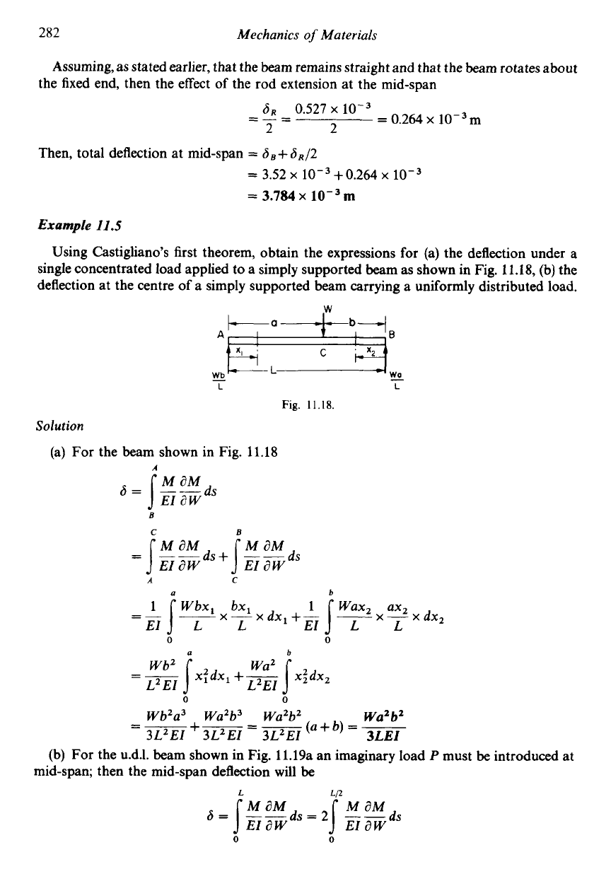
Using Castigliano's first theorem, obtain the expressions for
(a)
the deflection under
a
single concentrated load applied to
a
simply supported beam as shown in Fig. 11.18,
(b)
the
deflection at the centre
of
a simply supported beam carrying a uniformly distributed load.
AF&;B
!e
wo
Fig.
11.18.
L
L
Solution
(a) For the beam shown in Fig. 11.18
s
=
]ggds
B
C
B
a
b
-
0 0
a
b
wa2
Wb2
L~
EI
L2El
=
-
jx:dx,
+-
0
0
Wb2a3 Wa2b3
Wa2b2
Wa2b2
3L2EI
3L2EI 3L2E1
3LEI
=-
+-=-
(U
+
b)
=
~
(b) For the u.d.1. beam shown in Fig. 11.19a an imaginary load
P
must
be
introduced
at
mid-span; then the mid-span deflection will
be
L
Ll2
