Harris C.M., Piersol A.G. Harris Shock and vibration handbook
Подождите немного. Документ загружается.

DYNAMIC VIBRATION ABSORBERS AND AUXILIARY MASS DAMPERS 6.15
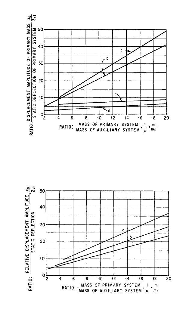
FIGURE 6.15 Displacement amplitude of the primary mass as a function
of the size of the auxiliary mass: (a) auxiliary system coupled only by
Coulomb friction (α=0) with optimum damping; (b) auxiliary system cou-
pled only by viscous damping (α=0) of optimum value; (c) auxiliary system
coupled by spring and damper tuned to frequency of primary system (α=
1) with optimum damping; (d) auxiliary system coupled by spring and
damper with optimum tuning [α=1/(1 +µ)] and optimum damping.
FIGURE 6.16 Relative displacement amplitude between the primary
mass and the auxiliary mass as a function of the size of the auxiliary mass:
(a) auxiliary system coupled by spring and damper with optimum tuning
[α=1/(1 +µ)] and optimum damping; (b) auxiliary system coupled only by
viscous damping (α=0) of optimum value; (c) auxiliary system coupled by
spring and damper tuned to frequency of primary system (α=1) with opti-
mum damping.
8434_Harris_06_b.qxd 09/20/2001 11:26 AM Page 6.15
The Use of Auxiliary Mass Absorbers for Vibration Energy Dissipation.
When a complicated mass-spring system is analyzed for possible vibration troubles,
it is customary to compute the natural frequencies of the several modes of vibration
of the system. The vibration amplitudes and stresses are estimated by making an
energy balance between the energy input from the various exciting forces and the
energy dissipated in the system and external reactions. From this point of view, it is
desirable to know how much energy is dissipated in auxiliary mass systems and what
value the damping constant should have in an auxiliary mass system of limited size
to give maximum energy absorption. This is not the best criterion for determining
the optimum damping because it neglects the effects of damping upon the mode
shapes and the frequencies of the system, but it is generally adequate when com-
pared with the other uncertainties of the calculations. Methods of designing
dampers for torsional systems are given in Chap. 38.
Optimum Viscous Damping to Give Large Energy Absorption in an Auxiliary
Mass Absorber.
8
Suppose the amplitude of motion of the primary system is unaf-
fected by the auxiliary mass system which is attached to it. All energy absorption
occurs in the damping element of the auxiliary mass system and is obtained by inte-
grating the differential work done in the damper over a vibration cycle. The force
exerted by damping is c ˙x
r
(the subscripts a are dropped), where x
r
is the relative
motion and the increment of work is c ˙x
r
dx
r
= c ˙x
r
2
dt. If x
r
= x
r 0
cos ωt, the work done
over a cycle is
V =
cω
2
x
r 0
2
sin
2
ωt dt =πcx
r 0
2
ω (6.29)
For a damper attached to a support moving in harmonic motion of amplitude x
0
,
the relative motion x
r
is given by Eq. (6.1). The amplitude of relative motion is
6.16 CHAPTER SIX
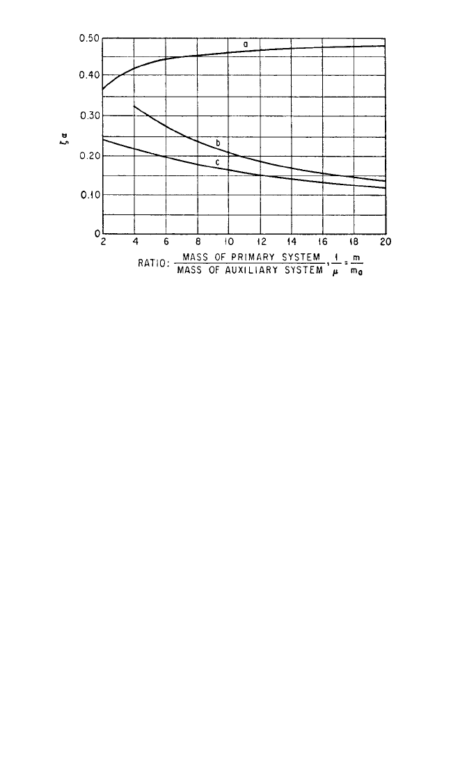
FIGURE 6.17 Curves showing damping required in auxiliary mass systems
to minimize vibration amplitude of primary system: (a) auxiliary mass cou-
pled by viscous damping only (α=0); (b) auxiliary system coupled by spring
and damper tuned to frequency of primary system (α=1); (c) auxiliary sys-
tem coupled by spring and damper with optimum tuning [α=1/(1 +µ)]. The
ordinate of the curves is ζα, where ζ is the fraction of critical damping in the
auxiliary system [Eq. (6.4)] and α is the tuning parameter [Eq. (6.15)].
8434_Harris_06_b.qxd 09/20/2001 11:26 AM Page 6.16
x
r 0
==
Substituting the above value of x
r0
in Eq. (6.29) and integrating,
V == (6.30)
Equation (6.30) can be used to find the tuning and the damping that gives the max-
imum energy dissipation when the amplitude of the forcing motion remains con-
stant. Placing ∂V/∂β
a
= 0, the optimum value of β
a
for given values of ζ is found from
(β
a
)
2
opt
= (2ζ
2
− 1) ± 2 1
−
ζ
2
+
ζ
4
(6.31)
Placing ∂V/∂ζ = 0, the optimum value of ζ for a given value of β
a
is
ζ
opt
= (6.32)
Where k = 0, the optimum damping is determined most conveniently by setting
∂V/∂c = 0, using the dimensional form of Eq. (6.30), and determining c for maximum
energy absorption:
c
opt
= mω (6.33)
Auxiliary Mass Damper Using Coulomb Friction Damping.
9
Dampers relying
on Coulomb friction (i.e., friction whose force is constant) have been widely used. A
damper relying on dry friction and connected to its primary system with a spring is
too complicated to be analyzed or to be adjusted by experiment. For this reason, a
damper with Coulomb friction has been used with only friction damping connecting
the seismic mass (usually in a torsional application) to the primary system.
1,2,9
Because the motion is irregular, it is necessary to use energy methods of analysis.
The analysis given here applies to the case of linear vibration. By analogy, the appli-
cation to torsional or other vibration can be made easily (see Table 2.1 for analogous
parameters).
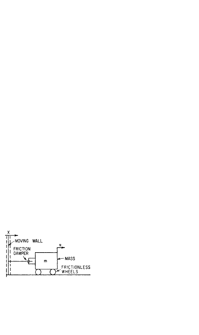
Consider the system shown in Fig.
6.18. It consists of a mass resting on
wheels that provide no resistance to
motion and are connected through a
friction damper to a wall that is moving
sinusoidally. The friction damper con-
sists of two friction facings that are held
on opposite sides of a plate by a spring
that can be adjusted to give a desired
clamping force. The maximum force that
can be transmitted through each inter-
face of the damper is the product of the
normal force and the coefficient of friction; the maximum total force for the damper
is the summation over the number of interfaces.
Consider the velocity diagrams shown in Fig. 6.19A, B, and C. In these diagrams
the velocity of the moving wall, ˙x = x
0
ω sin ωt, is shown by curve 1; the velocity ˙u of
the mass is shown by curve 2. The force exerted by the damper when slipping occurs
is F
s
. When F
s
≥ mü, the mass moves sinusoidally with the wall. When F
s
< mü, slip-
1 −β
a
2
2β
a
πx
0
2
mω
2
(2ζβ
a
)β
a
2
(1 −β
a
2
)
2
+ (2ζβ
a
)
2
πcωx
0
2
m
2
ω
4
(k − mω
2
)
2
+ c
2
ω
2
β
a
2
x
0
(1
−
β
a
2
)
2
+
(
2
ζβ
a
)
2
mω
2
x
0
(k
−
m
ω
2
)
2
+
c
2
ω
2
DYNAMIC VIBRATION ABSORBERS AND AUXILIARY MASS DAMPERS 6.17
FIGURE 6.18 Schematic diagram of auxiliary
mass absorber with Coulomb friction damping.
8434_Harris_06_b.qxd 09/20/2001 11:26 AM Page 6.17
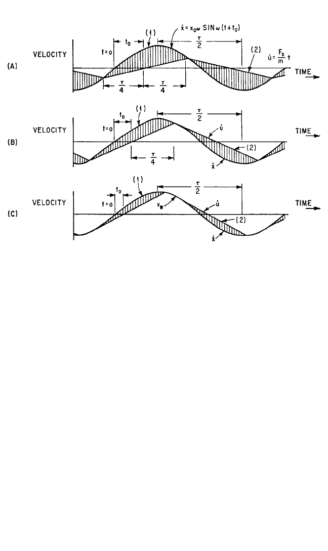
ping occurs in the damper and the mass is accelerated at a constant rate. Since a con-
stant acceleration produces a uniform change in velocity, the velocity of the mass
when the damper is slipping is shown by straight lines.The relative velocity between
the wall and the mass is shown by the vertical shading.
Figure 6.19A applies to a damper with a low friction force. The damper slips con-
tinuously. In Fig. 6.19B the velocities resulting from a larger friction force are shown.
Slipping disappears for certain portions of the cycle. Where the wall and the mass
have the same velocity, their accelerations also are equal. Slipping occurs when the
force transmitted by the damper is not large enough to keep the mass accelerating
with the wall. Since at the breakaway point the accelerations of the wall and mass
are equal, their velocity-time curves have the same slope; i.e., the curves are tangent
at this point. In Fig. 6.19C, the damping force is so large that the mass follows the
wall for a considerable portion of the cycle and slips only where its acceleration
becomes greater than the value of F
s
/m. A slight increase in the clamping force or in
the coefficient of friction locks the mass to the wall; then there is no relative motion
and no damping.
Because of the nature of the damping force, the damping provided by the friction
damper can be computed most practically in terms of energy. If the friction force
exerted through the damper is F
s
, the energy dissipated by the damper is the prod-
uct of the friction force and the total relative motion between the mass and the mov-
ing wall.The time reference is taken at the moment when the auxiliary mass m has a
zero velocity and is being accelerated to a positive velocity, Fig. 6.19A. Let the period
of the vibratory motion of the wall be τ=2π/ω, where ω is the angular frequency of
the wall motion. By symmetry, the points of no slippage in the damper occur at times
6.18 CHAPTER SIX
FIGURE 6.19 Velocity-time diagrams for motion of wall (curve 1) and mass (curve 2) of Fig.
6.18. The conditions for a small damping force are shown at (A), for an intermediate damping
force at (B), and for a large damping force at (C). The relative velocity between the wall and the
mass is indicated by vertical shading.
8434_Harris_06_b.qxd 09/20/2001 11:26 AM Page 6.18

−τ/4, τ/4, and 3τ/4. Let the time when the velocity of the wall is zero be −t
0
; then the
velocity of the wall ˙x is
˙x =+x
0
ω sin ω(t + t
0
)
The velocity ˙u of the mass for −τ/4 < t <τ/4 is
˙u = üt = t
The velocities of the wall and the mass are equal at time t =τ/4:
x
0
ω sin ω
+ t
0
=
Since ωτ/4 =π/2, sin ω(τ/4 + t
0
) = cos ωt
0
. Therefore
cos ωt
0
=
The relative velocity between the moving wall and the mass is ˙x − ˙u, and the total rel-
ative motion is the integral of the relative velocity over a cycle. Note that the area
between the two curves for the second half of the cycle is the same as for the first.
Hence, the work V per cycle is
V = 2
τ/4
−τ/4
F
s
(˙x − ˙u) dt = 4F
s
x
0
1 −
2
(6.34)
Optimum damping occurs when the work per cycle is a maximum. It can be deter-
mined by setting the derivative of V with respect to F
s
in Eq. (6.34) equal to zero and
solving for F
s
:
(F
s
)
opt
= mω
2
x
0
(6.35)
Energy absorption per cycle with optimum damping is, from Eq. (6.34),
V
opt
= mω
2
x
0
2
(6.36)
A comparison of the effectiveness of the Coulomb friction damper with other types
is given in Fig. 6.15.
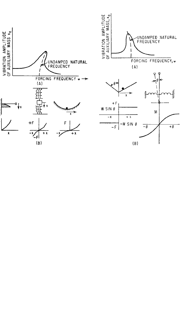
EFFECT OF NONLINEARITY IN THE SPRING OF
AN AUXILIARY MASS DAMPER
It is possible to extend the range of frequency over which a dynamic absorber is effec-
tive by using a nonlinear spring.
10–12
When a nonlinear spring is used, the natural fre-
quency of the absorber is a function of the amplitude of vibration; it increases or
decreases, depending upon whether the spring stiffness increases or decreases with
deflection. Figure 6.20A shows a typical response curve for a system with increasing
spring stiffness; Fig. 6.20B illustrates types of systems having increasing spring stiff-
ness and shows typical force-deflection curves. Figure 6.21A shows a typical response
4
π
2
π
F
s
π
2mx
0
ω
2
π
2x
0
ω
2
F
s
m
τ
4
F
s
m
τ
4
F
s
m
DYNAMIC VIBRATION ABSORBERS AND AUXILIARY MASS DAMPERS 6.19
8434_Harris_06_b.qxd 09/20/2001 11:26 AM Page 6.19
curve for a system of decreasing spring stiffness; Fig. 6.21B illustrates types of systems
having decreasing stiffnesses and shows typical force-deflection curves.
To compute the equivalent mass at a given frequency when a nonlinear spring is
used, it is necessary to use a trial-and-error procedure. By the methods given in
Chap. 4, compute the natural frequency of the auxiliary mass system, assuming the
point of attachment fixed, as a function of the amplitude of motion of the auxiliary
mass. This will result in a curve similar to the dotted curves in Figs. 6.20A and 6.21A.
At the given frequency, compute β
a
in Eq. (6.4) in terms of the tuned frequency of
the absorber at zero amplitude. (The tuned frequency will change with amplitude
because the spring constant changes.) With this value of β
a
compute the equivalent
mass from Eq. (6.6). With this mass in the system, compute the amplitude of motion
x
0
of the primary mass to which the auxiliary system is attached [Eq. (6.7)] and the
amplitude of the relative motion x
r 0
= v
2
(1 − v
2
)x
0
. Using this value of x
r 0
, ascertain
the corresponding value of resonance frequency of the system from the computed
curve, and compute the new value of β
a
. Repeat the process until the value of β
a
remains unchanged upon repeated calculation.
A dynamic absorber having a nonlinear characteristic can be used to introduce
nonlinearity into a resonant system. This can be useful in the case where a machine
passes through a resonance rapidly as the speed is increased but slowly as the speed is
decreased. In bringing this machine up to speed, there is a natural frequency that
comes into strong resonance, giving a critical speed. A strongly nonlinear dynamic
absorber tuned at low amplitudes to the optimum frequency for the damped absorber
6.20 CHAPTER SIX
FIGURE 6.20 Auxiliary mass damper with
nonlinear spring having stiffness that increases
as deflection increases. The response to forced
vibration and the natural frequency are shown
at (A). Several arrangements of nonlinear sys-
tems with the corresponding force-deflection
curves are shown at (B).
FIGURE 6.21 Auxiliary mass damper with
nonlinear spring having stiffness that decreases
as deflection increases. The response to forced
vibration and the natural frequency are shown
at (A). Two arrangements of nonlinear systems
with the corresponding force-deflection curves
are shown at (B).
8434_Harris_06_b.qxd 09/20/2001 11:26 AM Page 6.20
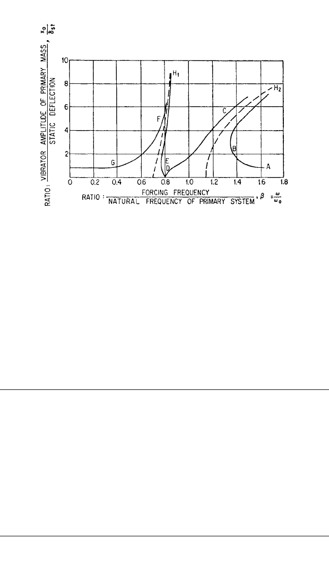
can be used to reduce the effects of the critical speed.Two resonant peaks will be intro-
duced, as shown on curve 1 of Fig. 6.13. By making the dynamic absorber nonlinear, so
that the stiffness becomes greater as the amplitude of vibration is increased, the peaks
are bent over to provide the response curve shown in Fig. 6.22. In starting, the machine
is accelerated through the two critical speeds so fast that a resonance is unable to build
up. In coasting to a stop, there would be ample time for significant amplitudes to build
up if the nonlinearity did not exist. Because of the nonlinearity, the amplitude of vibra-
tion as a function of speed (since β is proportional to speed) follows the path A, B, C,
D, E, F, G and never reaches the extreme amplitudes H
1
and H
2
.
MULTIMASS ABSORBERS
In general, only one mass is used in a dynamic absorber. However, it is possible to
provide a dynamic absorber that is effective for two or more frequencies by attach-
ing an auxiliary mass system that resonates at the frequencies that are objectionable.
The principle that would make such a dynamic absorber effective is utilized in the
design of the elastic system of a ship’s propulsion plant driven by independent high-
pressure and low-pressure turbines. By making the frequencies of the two branches
about the reduction gear identical, the gear becomes a node for one of the resonant
modes. Then it is impossible to excite the mode of vibration where one turbine
branch vibrates against the other as a result of excitation transmitted by the pro-
peller shaft to that node.
DISTRIBUTED MASS ABSORBERS
It is possible to use distributed masses as vibration dampers. Consider an undamped
rod of distributed mass and elasticity attached to a foundation that vibrates the rod
DYNAMIC VIBRATION ABSORBERS AND AUXILIARY MASS DAMPERS 6.21
FIGURE 6.22 Motion of the primary mass, as a function of forcing fre-
quency, in a system having a nonlinear dynamic absorber whose natural fre-
quency increases with amplitude. The mass of the absorber is 0.25 times the
mass of the primary system (µ=0.25).
8434_Harris_06_b.qxd 09/20/2001 11:26 AM Page 6.21
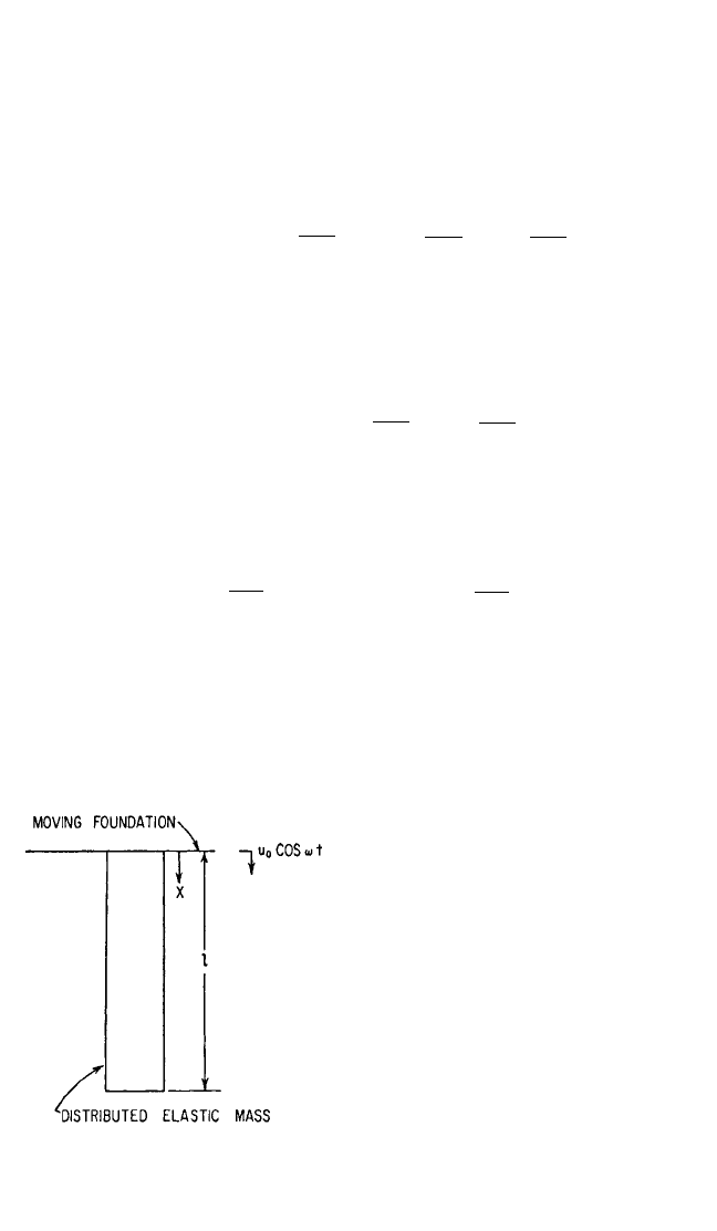
axially, as shown in Fig. 6.23. The differential equation for the motion of this rod is
derived in Chap. 7. The values of the constants are set by the boundary conditions:
Stress = E = 0 where x = l
(6.37)
u = u
0
cos ωt where x = 0
The solution of the equation of motion is
u = u
0
cos ωt
cos
x + tan
l sin
x
(6.38)
= u
0
cos ωt
where E is the modulus of elasticity and γ is the weight density of the material.When
x = 0, the force F on the foundation is
F = SE
0
= SEu
0
tan
l
(6.39)
where S is the cross-sectional area of the bar. It is apparent that as the argument of
the tangent has successive values of π/2, 3π/2, 5π/2,...,the force exerted on the
foundation becomes infinite. The distributed mass acts as a dynamic absorber
enforcing a node at its point of attachment. By tuning the mass so that
l = or l =
(6.40)
the distributed mass acts as a dynamic absorber for not only the fundamental fre-
quency ω/2π but also for the third, fifth, seventh,...harmonics of the fundamental.
The above solution neglects damping. It is possible to consider the effect of
damping by including a damping term in the differential equation. The stress in an
element is assumed to be the sum of a deformation stress and a stress related to the
velocity of strain:
σ=E +µ (6.41)
where ε=∂u/∂x is the strain. Then the
differential equation becomes
E +µ = (6.42)
Since the absorber is excited by a founda-
tion moving with a frequency f =ω/2π,
u may be expressed as Ru
1
e
jωt
and the par-
tial differential equation can be written as
the ordinary linear differential equation
E + jωµ + = 0
This equation may be written
γω
2
u
1
g
d
2
u
1
dx
2
d
2
u
1
dx
2
∂
2
u
∂t
2
γ
g
∂
3
u
∂x
2
∂t
∂
2
u
∂x
2
d
dt
E
g
γ
nπ
2ω
nπ
2
γω
2
Eg
γω
2
Eg
γω
2
Eg
∂u
∂x
cos γ
ω
2
/
E
g
(1 − x)
cos γ
ω
2
/
E
g
l
γω
2
Eg
γω
2
Eg
γω
2
Eg
∂u
∂x
6.22 CHAPTER SIX
FIGURE 6.23 Elastic body with distributed
mass used as auxiliary mass damper.
8434_Harris_06_b.qxd 09/20/2001 11:26 AM Page 6.22

1 +
+ u
1
= 0 (6.43)
Since Eq. (6.43) is a second-order linear differential equation, the solution may be
written
u = A
1
e
β
1
x
+ A
2
e
β
2
x
(6.44)
where β
1
and β
2
are the two roots of the equation
β
2
= (6.45)
For small values of µ, by a binomial expansion of the denominator,
±β =
+ j
ω (6.46)
where µ is defined by Eq. (6.41).
The boundary conditions to be met by the damper are:
At x = 0: u = u
0
therefore, A
1
+ A
2
= u
0
(6.47)
At x = l: σ=(E + jωµ) = 0 therefore, A
1
e
βl
− A
2
e
−βl
= 0
Solving Eqs. (6.47) for A
1
and A
2
and substituting the result in Eq. (6.44),
u = u
0
(6.48)
The force exerted on the foundation by the damper is
F
(x = 0)
= Sσ
(x = 0)
=−Su
0
(E + jωµ) β tanh βl (6.49)
where S is the cross-section area of the bar. When the complex value of β as given in
Eq. (6.46) is substituted in Eq. (6.49), the following value for the dynamic force
exerted on the foundation is obtained:
F
(x = 0)
=
1 +
sin 2
ωl
+ sinh
ωl
SE
ωu
0
cos 2
ωl
+ cosh
ωl
+ j
sin 2
ωl
−
1 +
sinh
(6.50)
cos 2
ωl
+ cosh
ωl
A plot of the real and imaginary values of F
(x = 0)
/SE
ωu
0
is given in Fig. 6.24 for
zero damping and for a damping coefficient µω/E = 0.1 as a function of a tuning
γ
Eg
γ
Eg
µω
E
γ
Eg
γ
Eg
µω
E
µ
2
ω
2
2E
2
γ
Eg
µω
2E
γ
Eg
µω
E
γ
Eg
γ
Eg
γ
Eg
µω
E
µω
2E
γ
Eg
µ
2
ω
2
2E
2
cosh β(l − x)
cosh βl
∂u
∂x
γ
Eg
µω
2
E
γ
Eg
1
2
−(γ/E
g
)ω
2
1 + (jµω/E)
γω
2
Eg
d
2
u
1
dx
2
µωj
E
DYNAMIC VIBRATION ABSORBERS AND AUXILIARY MASS DAMPERS 6.23
8434_Harris_06_b.qxd 09/20/2001 11:26 AM Page 6.23
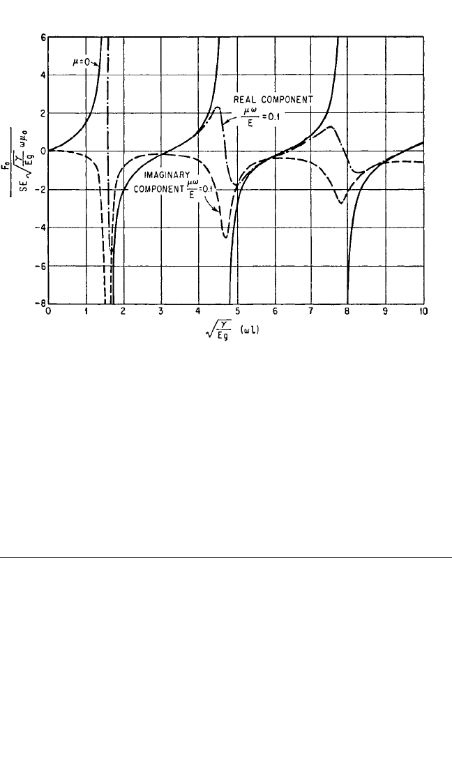
parameter γ/
E
g
(ω
l)
. Damping decreases the effectiveness of the distributed mass
damper substantially, particularly for the higher modes.
Use of a distributed mass as a vibration absorber is practical only at very high fre-
quency; otherwise, too long a length is required.
PRACTICAL APPLICATIONS OF AUXILIARY MASS
DAMPERS AND ABSORBERS TO SINGLE
DEGREE-OF-FREEDOM SYSTEMS
THE DYNAMIC ABSORBER
The dynamic absorber, because of its tuning, can be used to eliminate vibration only
where the frequency of the vibration is constant. Many pieces of equipment to which
it is applied are operated by alternating current. So that it can be used for time keep-
ing, the frequency of this alternating current is held remarkably constant. For this
reason, most applications of dynamic absorbers are made to mechanisms that oper-
ate in synchronism from an ac power supply.
An application of a dynamic absorber to the pedestal of an ac generator having
considerable vibration is shown in Fig. 6.25, where the relative sizes of absorber and
pedestal are shown approximately to scale. In this case, the application is made to a
complicated structure and the mass of the absorber is much less than that of the pri-
mary system; however, since the frequency of the excitation is constant, the dynamic
6.24 CHAPTER SIX
FIGURE 6.24 Real and imaginary components of the force applied to a vibrating body by the dis-
tributed mass damper shown in Fig. 6.23. These relations are given mathematically by Eq. (6.50), and
the terms are defined in connection with Eq. (6.38). The curves are for a value of the damping coeffi-
cient µω/E = 0.1, where µ is defined by Eq. (6.41).
8434_Harris_06_b.qxd 09/20/2001 11:26 AM Page 6.24