Harris C.M., Piersol A.G. Harris Shock and vibration handbook
Подождите немного. Документ загружается.

absorber reduces the vibration. When
the mass ratio is small, it is important
that the absorber be accurately tuned
and that the damping be small. In this
case, the excitation was the unbalance in
the turbine rotor which was elastically
connected to the pedestal through the
flexibility of the shaft. If the absorber
were ideally effective, there would be no
forces at the frequency of the shaft
speed; therefore, there would be no dis-
placements from the pedestal where the
force is neutralized through the remain-
der of the structure.
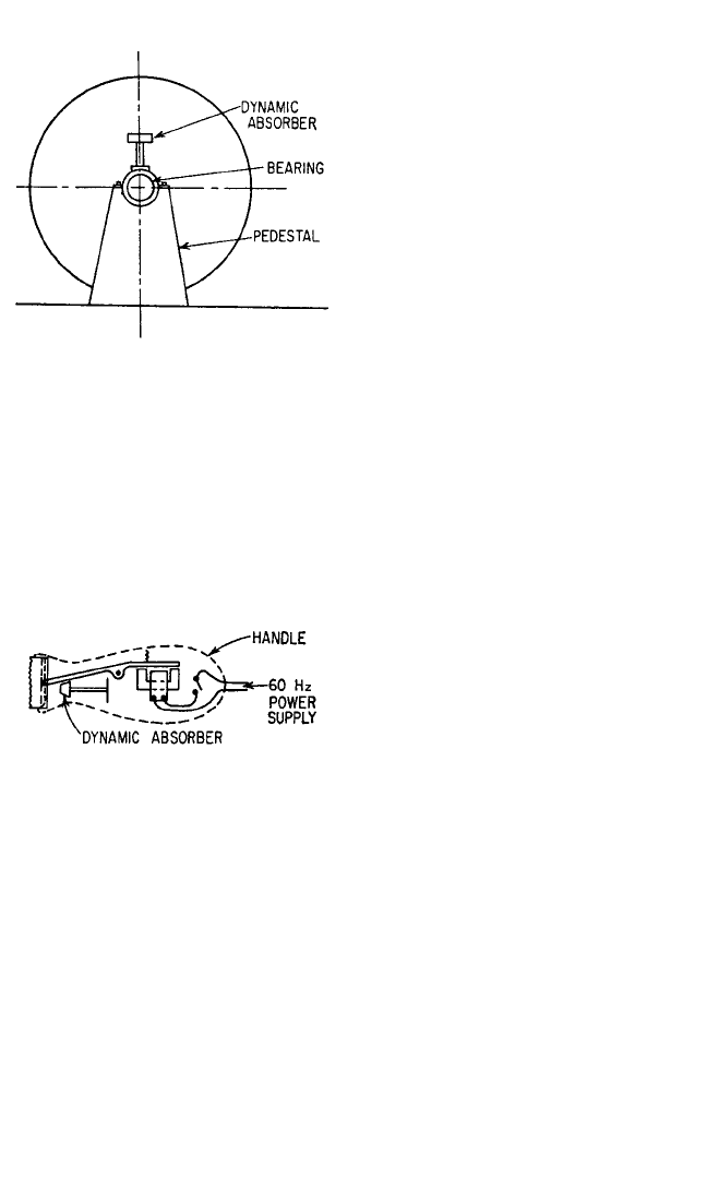
The dynamic absorber has been
applied to the electric clipper shown in
Fig. 6.26. The structure consisting of the
cutter blade and its driving mechanism is actuated by the magnetic field at a fre-
quency of 120 Hz, as a result of the 60-Hz ac power supply. The forces and torques
required to move the blade are balanced by reactions on the housing, causing it to
vibrate. The dynamic absorber tuned to a frequency of 120 Hz enforces a node at the
location of its mass. Since this is approximately the center-of-gravity of the assembly
of the cutter and its driving mechanism, the absorber effectively neutralizes the
unbalanced force. The moment caused by the rotation of the moving parts is still
unbalanced. A second very small dynamic absorber placed in the handle of the clip-
per could enforce a node at the handle
and substantially eliminate all vibration.
The design of these absorbers is simple
after the unbalanced forces and torques
generated by the cutter mechanism are
computed. The sum of the inertia forces
generated by the two absorbers, m
1
x
1
ω
2
+ m
2
x
2
ω
2
(where m
1
and x
1
are the mass
and amplitude of motion of the first
absorber, m
2
and x
2
are the correspond-
ing values for the second absorber, and
ω=240π), must equal the unbalanced force generated by the clipper mechanism.
The torque generated by the two absorbers must balance the torque of the mecha-
nism. Since the value of ω
2
is known, the values of m
1
x
1
and m
2
x
2
can be determined.
Weights that fit into the available space with adequate room to move are chosen,
and a spring is designed of such stiffness that the natural frequency is 120 Hz.
Because of the desirable balancing properties of the simple dynamic absorber
and the constancy of frequency of ac power, it might be expected that devices oper-
ating at a frequency of 120 Hz would be used more widely. However, their applica-
tion is limited because the frequency of vibration is too high to allow large
amplitudes of motion.
REDUCTION OF ROLL OF SHIPS BY AUXILIARY TANKS
An interesting application of auxiliary mass absorbers is found in the auxiliary tanks
used to reduce the rolling of ships,
1,13
as shown in Fig. 6.27.When a ship is heeled, the
DYNAMIC VIBRATION ABSORBERS AND AUXILIARY MASS DAMPERS 6.25
FIGURE 6.25 Application of a dynamic ab-
sorber to the bearing pedestal of an ac generator.
FIGURE 6.26 Application of a dynamic
absorber to a hair clipper.
8434_Harris_06_b.qxd 09/20/2001 11:26 AM Page 6.25
restoring moment k
r
φ acting on it is pro-
portional to the angle of heel (or roll).
This restoring moment acts to return the
ship (and the water that moves with it)
to its equilibrium position. If I
s
repre-
sents the polar moment of inertia of the
ship and its entrained water, the differ-
ential equation for the rolling motion of
the ship is
I
s
¨
φ+k
r
φ=M
s
(6.51)
where M
s
represents the rolling moments
exerted on the ship, usually by waves.
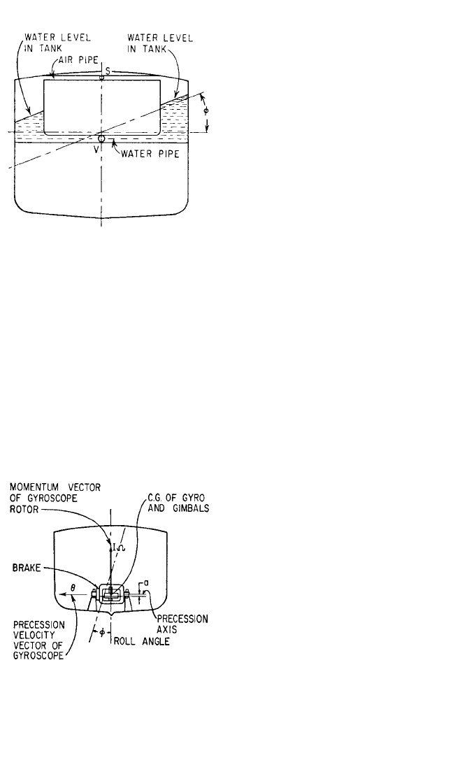
To reduce rolling of the ship, auxil-
iary wing tanks connected by pipes are
used. The water flowing from one tank
to another has a natural frequency that
is determined by the length and cross-
sectional area of the tube connecting the
tanks. The damping is controlled by restricting the flow of water, either with a valve
S in the line that allows air to flow between the tanks (Fig. 6.27) or with a valve V in
the water line. Since the tanks occupy valuable space, the mass ratio of the water in
the tanks to the ship is small. Fortunately, the excitation from waves generally is not
large relative to the restoring moments, and roll becomes objectionable only
because the normal damping of a ship in rolling motion is not very large. The use of
antirolling tanks in the German luxury liners Bremen and Europa reduced the max-
imum roll from 15 to 5°.
REDUCTION OF ROLL OF SHIPS BY GYROSCOPES
A large gyroscope may be used to re-
duce roll in ships, as shown in Fig.
6.28.
1,14
In response to the velocity of
roll of a ship, the gyroscope precesses in
the plane of symmetry of the ship. By
braking this precession, energy can be
dissipated and the roll reduced. The
torque exerted by the gyroscope is pro-
portional to the rate of change of the
angular momentum about an axis per-
pendicular to the torque. Letting I rep-
resent the polar moment of inertia of
the gyroscope about its spin axis and
˙
θ
the angular velocity of precession of the
gyroscope, then the equation of motion
of the ship is
I
s
¨
φ+k
r
φ+IΩ
˙
θ=M
s
(6.52)
Assume that the gyroscope has (1) a moment of inertia about the precession axis
of I
g
, (2) a weight of W, and (3) that its center-of-gravity is below the gimbal axis (as
6.26 CHAPTER SIX
FIGURE 6.27 Cross section of ship equipped
with antiroll tanks. The flow of water from one
tank to the other tends to counteract rolling of
the ship.
FIGURE 6.28 Application of a gyroscope to a
ship to reduce roll.
8434_Harris_06_b.qxd 09/20/2001 11:26 AM Page 6.26

it must be for the gyro to come to equilibrium in a working position) a distance a, as
shown in Fig. 6.28. Then the equation of motion of the gyroscope is
I
g
¨
θ+W
a
θ+c
˙
θ−IΩ
˙
φ=0 (6.53)
where Ω is the spin velocity of the gyroscope. From Eq. (6.53), for a roll frequency of
ω, the angle of precession of the gyroscope is
θ= (6.54)
The torque exerted on the ship is
IΩ
˙
θ= (6.55)
The equivalent moment of inertia of the gyroscope system in its reaction on the ship is
(6.56)
By analogy with the steps of Eqs. (6.2) through (6.7), it follows that
=
(6.57)
where the parameters are defined in terms of ship and gyro constants as follows:
β
g
=β=ζ= µ=ψ
st
=
Because IΩ can be made large by using a large gyro rotor and spinning it at a high
speed, and Wa can be made small by choice of a design, the value of µ can be made
quite large even though I
s
is large. In one experimental ship, µ=20 was obtained.
Even with this large value of µ, the precession angle of the gyroscope would become
very large for optimum damping.Therefore it is necessary to use much more damp-
ing than optimum. Gyro stabilizers were used on the Italian ship Conte di Savoia;
they are sometimes installed on yachts.
Both antirolling tanks and gyro stabilizers are more effective if they are active
rather than passive. Activated dampers are considered below.
AUXILIARY MASS DAMPERS APPLIED TO
ROTATING MACHINERY
An important industrial use of auxiliary mass systems is to neutralize the unbalance
of centrifugal machinery.A common application is the balance ring in the spin dryer
of home washing machines. The operation of such a balancer is dependent upon the
basket of the washer rotating at a speed greater than the natural frequency of its
support.The balance ring is attached to the washing machine basket concentric with
its axis of rotation, as shown in Fig. 6.29.
Consider the washing machine basket shown in Fig. 6.29. When its center-of-
gravity does not coincide with its axis of rotation and it is rotating at a speed lower
M
s
k
r
(IΩ)
2
WaI
s
c
2 W
a
I
g
ω
k
r
/
I
s
ω
W
a
/I
g
(1 −β
g
2
)
2
+ (2ζβ
g
)
2
[(1 −β
g
2
)(1 −β
2
) −β
2
µ]
2
+ (2ζβ
g
)
2
(1 −β
2
)
2
φ
φ
st
IΩ
2
−I
g
ω
2
+ Wa + cjω
−(IΩ)
2
ω
2
φ
−I
g
ω
2
+ Wa + jcω
jIΩωφ
−I
g
ω
2
+ Wa − jcω
DYNAMIC VIBRATION ABSORBERS AND AUXILIARY MASS DAMPERS 6.27
8434_Harris_06_b.qxd 09/20/2001 11:26 AM Page 6.27
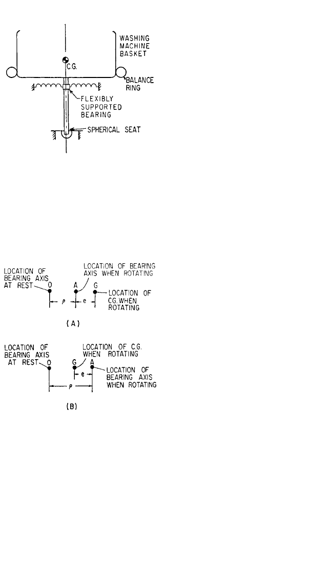
than its critical speed (corresponding to
the natural frequency in rocking motion
about the spherical seat), the centrifugal
force tends to pull the rotational axis in
the direction of the unbalance. This
effect increases with an increase in rota-
tional speed until the critical speed is
reached. At this speed the amplitude
would become infinite if it were not for
the damping in the system. Above the
critical speed, the phase position of the
axis of rotation relative to the center-of-
gravity shifts so that the basket tends to
rotate about its center-of-gravity with
the flexibly supported bearing moving in
a circle about an axis through the center-
of-gravity. The relative positions of the bearing center and the center-of-gravity are
shown in Fig. 6.30A and B.
Since the balance ring is circular with a smooth inner surface, any weights or fluids
contained in the ring can be acted upon only by forces directed radially.When the ring
is rotated about a vertical axis, the weights or fluids will move within the ring in such a
manner as to be concentrated on the side farthest from the axis of rotation. If this con-
centration occurs below the natural fre-
quency (Fig. 6.30A), the weights tend to
move further from the axis and the result-
ant center-of-gravity is displaced so as to
give a greater eccentricity. The points A
and G rotate about the axis O at the fre-
quency ω. The initial eccentricity of the
center-of-gravity of the washer basket
and its load from the axis of rotation is
represented by e, and ρ is the elastic dis-
placement of this center of rotation due
to the centrifugal force. Where the off-
center rotating weight is W, the unbal-
anced force is (W/
g
)(ρ+e)ω
2
[where ρ=
e/(1 −β
2
) and β
2
=ω
2
/ω
n
2
< 1] and acts in
the direction from A to G.
If the displacement of the weights or
fluids in the balance ring occurs above
the natural frequency, the center-of-
gravity tends to move closer to the
dynamic location of the axis.The action in
this case is shown in Fig. 6.30B. Then the
points A and G rotate about O at the fre-
quency ω. The unbalanced force is (W/
g
)(ρ+e)ω
2
[where ρ=e/(1 −β
2
) and β
2
=
ω
2
/ω
n
2
> 1]. This gives a negative force that acts in a direction from G to A. Thus the
eccentricity is brought toward zero and the rotor is automatically balanced. Because it
is necessary to pass through the critical speed in bringing the rotor up to speed and in
stopping it, it is desirable to heavily damp the balancing elements, either fluid or
weights.
In practical applications, the balancing elements can take several forms. The ear-
liest form consisted of two or more spheres or cylinders free to move in a race con-
6.28 CHAPTER SIX
FIGURE 6.29 Schematic diagram showing
location of balance ring on basket of a spin dryer.
FIGURE 6.30 Diagram in plane normal to
axis of rotation of spin dryer in Fig. 6.29. Rela-
tive positions of axes when rotating speed is less
than natural frequency are shown at (A); corre-
sponding diagram for rotation speed greater
than natural frequency is shown at (B).
8434_Harris_06_b.qxd 09/20/2001 11:26 AM Page 6.28
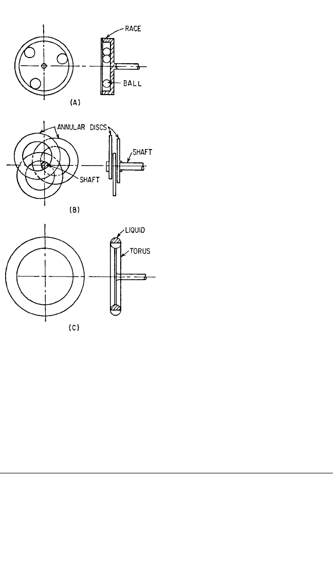
centric with the axis of the rotor, as
shown in Fig. 6.31A. A later modifica-
tion consists of three annular discs that
rotate about an enlarged shaft concen-
tric with the axis, as indicated in Fig.
6.31B. These are contained in a sealed
compartment with oil for lubrication
and damping. A fluid type of damper is
shown in Fig. 6.31C, the fluid usually
being a high-density viscous material.
With proper damping, mercury would
be excellent, but it is too expensive.
Therefore a more viscous, high-density
halogenated fluid is used.
The balancers must be of sufficient
weight and operate at such a radius that
the product of their weight and the max-
imum eccentricity they can attain is
equivalent to the unbalanced moment
of the load. This requirement makes the
use of the spheres or cylinders difficult
because they cannot be made large; it
makes the annular plates large because
they are limited in the amount of eccen-
tricity that can be obtained.
In a cylindrical volume 24 in. (61 cm)
in diameter and 2 in. (5 cm) thick, seven
spheres 2 in. (5 cm) in diameter can neu-
tralize 98.6 lb-in. (114 kg-cm) of unbal-
ance; three cylinders 4 in. (10 cm) in
diameter by 2 in. (5 cm) thick can neu-
tralize 255 lb-in. (295 kg-cm); three
annular discs, each
5
⁄
8 in. (1.6 cm) thick
with an outside diameter of 19.55 in. (50
cm) and an inside diameter of 10.45 in.
(26.5 cm) [the optimum for a center post
6 in. (15.2 cm) in diameter], can neutralize 250 lb-in. (290 kg-cm); and half of a 2-in.
(5-cm) diameter torus filled with fluid of density 0.2 lb/in
3
(5.5 gram/cm
3
) can neu-
tralize 609 lb-in. (700 kg-cm). Only the fluid-filled torus would be initially balanced.
AUXILIARY MASS DAMPERS APPLIED TO
TORSIONAL VIBRATION
Dampers and absorbers are used widely for the control of torsional vibration of
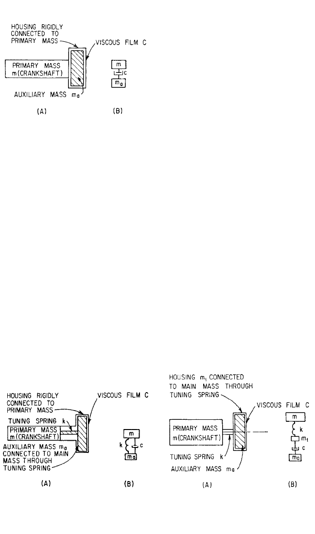
internal-combustion engines. The most common absorber is the viscous-damped,
untuned auxiliary mass unit shown in Fig. 6.32. The device is comprised of a cylin-
drical housing carrying an inertia mass that is free to rotate. There is a preset clear-
ance between the housing and the inertia mass that is filled with a silicone oil of
proper viscosity. Silicone oil is used because of its high viscosity index; i.e., its viscos-
ity changes relatively little with temperature. With the inertia mass and the damping
medium contained, the housing is seal-welded to provide a leakproof and simple
DYNAMIC VIBRATION ABSORBERS AND AUXILIARY MASS DAMPERS 6.29
FIGURE 6.31 Examples of balancing means
for rotating machinery: (A) spheres (or cylin-
ders) in a race; (B) annular discs rotating on
shaft; (C) damping fluid in torus.
8434_Harris_06_b.qxd 09/20/2001 11:26 AM Page 6.29
absorber. However, the silicone oil has
poor boundary lubricating properties
and if decomposed by a local hot spot
(such as might be caused by a reduced
clearance at some particular spot), the
decomposed damping fluid is abrasive.
Because of the simplicity of this un-
tuned damper, it is commonly used in
preference to the more effective tuned
absorber. However, it is possible to use
the same construction methods for a
tuned damper, as shown in Fig. 6.33. It is
also possible to mount the standard
damper with the housing for the un-
sprung inertia mass attached to the main
mass by a spring, as shown in Fig. 6.34. If the viscosity of the oil and the dimensions of
the masses and the clearance spaces are known, the damping effects of the dampers
shown in Figs. 6.32 and 6.34 can be computed directly in terms of the equations previ-
ously developed. The damper in Fig. 6.34 can be analyzed by treating the spring and
housing as additional elements in the main system and the untuned mass as a viscous
damped auxiliary mass. If the inertia of the housing is negligible, the inertia mass is
effectively connected to the main mass through a spring and a dashpot in series. The
two elements in series can be represented by a complex spring constant equal to
=
Where there is no damping in parallel with the spring, Eq. (6.3) becomes
m
eq
= km/(k − mω
2
)
Substituting the complex value of the spring constant, the effective mass is
m
eq
=
(6.58)
m
−mω
2
+ cjkω/(k + cjω)
ckjω
k + cjω
kcjω
k + cjω
1
(1/jcω) + (1/k)
6.30 CHAPTER SIX
FIGURE 6.32 Untuned auxiliary mass damper
with viscous damping. The application to a tor-
sional system is shown at (A), and the linear ana-
log at (B).
FIGURE 6.33 Tuned auxiliary mass damper
with viscous damping. The application to a tor-
sional system is shown at (A), and the linear ana-
log at (B).
FIGURE 6.34 Auxiliary mass damper with
viscous damping and spring-mounted housing.
The application to a torsional system is shown at
(A), and the linear analog at (B).
8434_Harris_06_b.qxd 09/20/2001 11:26 AM Page 6.30
In terms of the nondimensional parameters defined in Eq. (6.4):
m
eq
= m + j (6.59)
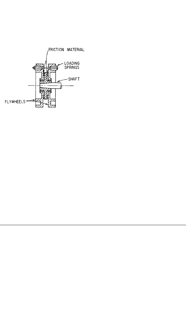
Before the advent of silicone oil with
its chemical stability and relatively con-
stant viscosity over service temperature
conditions, the damper most commonly
used for absorbing torsional vibra-
tion energy was the dry friction or Lan-
chester damper shown in Fig. 6.35. The
damping is determined by the spring
tension and the coefficient of friction at
the sliding interfaces. Its optimum value
is determined by the equation for a tor-
sional system analogous to Eq. (6.35) for
a linear system:
(T
s
)
opt
= Iω
2
θ
0
(6.60)
where T
s
is the slipping torque, I is the moment of inertia of the flywheels, and θ
0
is
the amplitude of angular motion of the primary system. The dry-friction-based Lan-
chester damper requires frequent adjustment, as the braking material wears, to
maintain a constant braking force.
It is possible to use torque-transmitting couplings that can absorb vibration
energy, as the spring elements for tuned dampers. The Bibby coupling (Fig. 6.36) is
used in this manner. Since the stiffness of this coupling is nonlinear, the optimum
tuning of such an absorber is secured for only one amplitude of motion.
A discussion of dampers and of their application to engine systems is given in
Chap. 38.
DYNAMIC ABSORBERS TUNED TO ORDERS OF
VIBRATION RATHER THAN CONSTANT
FREQUENCIES
In the torsional vibration of rotating machinery, it is generally found that exciting
torques and forces occur at the same frequency as the rotational speed or at multi-
ples of this frequency. The ratio of the frequency of vibration to the rotational speed
is called the order of the vibration q. Thus a power plant driving a four-bladed pro-
peller may have a torsional vibration whose frequency is 4 times the rotational speed
of the drive shaft; sometimes it may have a second torsional vibration whose fre-
quency is 8 times the rotational speed.These are called the fourth-order and eighth-
order torsional vibrations.
If a dynamic absorber in the form of a pendulum acting in a centrifugal field is
used, then its natural frequency increases linearly with speed. Therefore it can be
used to neutralize an order of vibration.
15–19
Consider a pendulum of length l and of mass m attached at a distance R from the
center of a rotating shaft, as shown in Fig. 6.37. Since the pendulum is excited by tor-
sional vibration in the shaft, let the radius R be rotating at a constant speed Ω with a
2
π
−2ζβ
a
3
m
β
a
4
− (2ζβ
a
)
2
(1 −β
a
2
)
(2ζβ
a
)
2
(1 −β
a
2
)
β
a
4
− (2ζβ
a
)
2
(1 −β
a
2
)
DYNAMIC VIBRATION ABSORBERS AND AUXILIARY MASS DAMPERS 6.31
FIGURE 6.35 Schematic cross section through
Lanchester damper.
8434_Harris_06_b.qxd 09/20/2001 11:26 AM Page 6.31
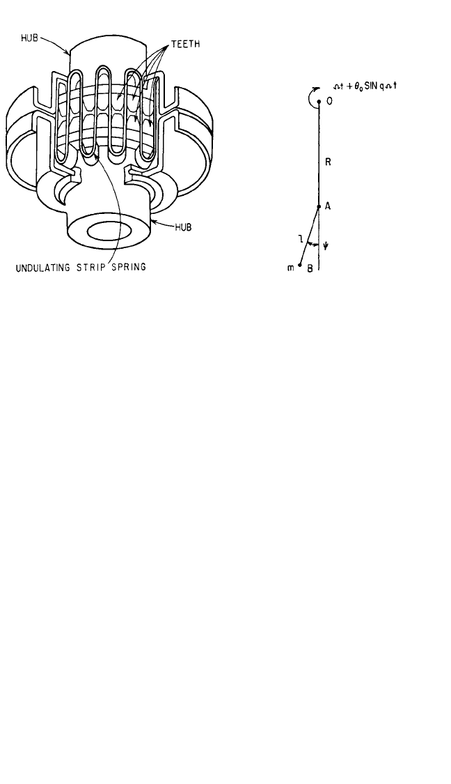
superposed vibration θ=θ
0
cos qΩt, where q represents the order of the vibration.
Then the angle of R with respect to any desired reference is Ωt +θ
0
cos qΩt. The
angle of the pendulum with respect to the radius R is defined as ψ=ψ
0
cos qΩt, as
shown by Fig. 6.37.
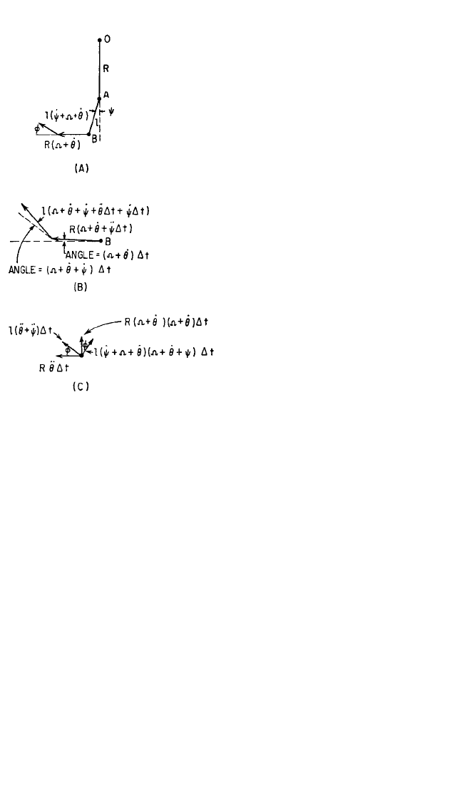
The acceleration acting on the mass m at position B is most easily ascertained by
considering the change in velocity during a short increment of time ∆t. The compo-
nents of velocity of the mass m at time t are shown graphically in Fig. 6.38A; at time
t +∆t, the corresponding velocities are shown in Fig. 6.38B. The change in velocity
during the time interval ∆t is shown in Fig. 6.38C. Since the acceleration is the change
in velocity per unit of time, the accelerations along and perpendicular to l are:
Acceleration along l:
(6.61)
Acceleration perpendicular to l:
(6.62)
Only the force −F, directed along the pendulum, acts on the mass m. Therefore the
equations of motion are
−F =−ml(Ω+
˙
θ+ ˙ψ)
2
− mR(Ω+
˙
θ)
2
cos ψ+R
¨
θ sin ψ
(6.63)
0 = ml(
¨
θ+¨ψ) + mR(Ω+
˙
θ)
2
sin ψ+mR
¨
θ cos ˙ψ
Assuming that ψ and θ are small, Eqs. (6.63) simplify to
l(
¨
θ+
¨
ψ) ∆t + R(Ω+
˙
θ)
2
∆t sin ψ+R
¨
θ∆t cos ψ
∆t
−l(Ω+
˙
θ+
˙
ψ
2
) ∆t − R(Ω+
˙
θ)
2
∆t cos ψ+R
¨
θ∆t sin ψ
∆t
6.32 CHAPTER SIX
FIGURE 6.36 Coupling used as elastic and
damping element in auxiliary mass damper for
torsional vibration. The torque is transmitted by
an undulating strip of thin steel interposed
between the teeth on opposite hubs. The stiff-
ness of the strip is nonlinear, increasing as
torque increases. Oil pumped between the strip
and teeth dissipates energy.
FIGURE 6.37 Schematic diagram of pendu-
lum absorber.
8434_Harris_06_b.qxd 09/20/2001 11:26 AM Page 6.32
Ft = m(R + l)Ω
2
(6.64)
l(
¨
θ+¨ψ) + RΩ
2
ψ+R
¨
θ=0
The second of Eqs. (6.64) upon substitu-
tion of θ=θ
0
cos qΩt and ψ=ψ
0
cos qΩt
yields
==
(6.65)
The torque M exerted at point 0 by the
force F is
M = RF sin ψ=RFψ when ψ is small
From Eqs. (6.64) and (6.65), when ψ is
small,
M = (6.66)
If a flywheel having a moment of iner-
tia I is accelerated by a shaft having an
amplitude of angular vibratory motion θ
0
and a frequency qΩ, the torque ampli-
tude exerted on the shaft is I(qΩ)
2
θ
0
.
Therefore, the equivalent moment of
inertia I
eq
of the pendulum is
I
eq
== (6.67)
When
= q
2
(6.68)
the equivalent inertia is infinite and the pendulum acts as a dynamic absorber by
enforcing a node at its point of attachment.
Where the pendulum is damped, the equivalent moment of inertia is given by an
equation analogous to Eqs. (6.4) and (6.5):
I
eq
= m(R + l)
2
= m(R + l)
2
−
(6.69)
where υ
2
= q
2
l/R and ζ=(c/2mΩ)l/
R
.
When the pendulum is attached to a single degree-of-freedom system as is shown
in Fig. 6.39, the amplitude of motion θ
a
of the flywheel of inertia I is given, by anal-
ogy to Eq. (6.7), as
2ζυ
3
j
(1 −
υ
2
)
2
+ (2ζ
υ
)
2
1 − υ
2
+ (2ζυ)
2
(1 −
υ
2
)
2
+ (2ζ
υ
)
2
1 + 2ζυj
(1 −
υ
2
) + 2ζ
υ
j
R
l
m(R + l)
2
1 − q
2
l/R
mR(R + l)
2
R − q
2
l
mq
2
R(R + l)
2
Ω
2
R − q
2
l
q
2
(l + R)
R − q
2
l
(qΩ)
2
(l + R)
−(qΩ)
2
l +Ω
2
R
ψ
0
θ
0
DYNAMIC VIBRATION ABSORBERS AND AUXILIARY MASS DAMPERS 6.33
FIGURE 6.38 Velocity vectors for the pendu-
lum absorber: (A) velocities at time t; (B) veloc-
ities at time t +∆t; (C) change in velocities during
time increment t.
8434_Harris_06_b.qxd 09/20/2001 11:26 AM Page 6.33

=
(6.70)
where 2ζυ =
µ
p
=
β
p
=
θ
st
=
The pendulum tends to detune when the amplitude of motion of the pendulum is
large, thereby introducing harmonics of the torque that it neutralizes.
17
Suppose the
shaft rotates at a constant speed Ω, i.e., θ
0
= 0, and consider the torque exerted on the
shaft as m moves through a large amplitude ψ
0
about its equilibrium position. Equa-
tions (6.63) become
F = ml(Ω+˙ψ)
2
+ mRΩ
2
cos ψ
(6.71)
l¨ψ+RΩ
2
sin ψ=0
A solution for the second of Eqs. (6.71) is
˙ψ=
cos
ψ
−
c
o
s
ψ
0
(6.72)
The solution of Eq. (6.72) involves elliptic integrals and is given approximately by
ψ=ψ
0
sin ωt
where ω=
Ω
and F(ψ
0
/2, π/2) is an elliptic function of the first kind whose value may be obtained
from tables.
Since ω/Ω=q (the order of the disturbance), the tuning of the damper will be
changed for large angles and becomes
q
2
=
2
(6.73)
The value of q
2
l/R = υ
2
used in Eqs. (6.69) and (6.70) is given in Fig. 6.40 as a function
of the amplitude of the pendulum.
Since the force exerted by the mass m is directed along the rod connecting it to
the pivot A (Fig. 6.37), the reactive torque on the shaft is
M = FR sin ψ
= mR
2
Ω
2
1 +
2
sin ψ+sin ψ cos ψ
= mR
2
Ω
2
(A
1
sin qΩt + A
2
sin 2qΩt + A
3
sin 3qΩt +
...
) (6.74)
˙ψ
Ω
l
R
π/2
F(ψ
0
/2, π/2)
R
l
π/2
F(ψ
0
/2, π/2)
R
l
2Ω
2
R
l
m
0
k
r
q
k
r
I
m(R + l)
2
I
cql
mR
(1 − υ
2
)
2
+ (2ζυ)
2
[(1 −
υ
2
)(1 −β
p
2
) −β
p
2
µ]
2
+ (2ζ
υ
)
2
[1 −β
p
2
−β
p
2
µ
p
]
2
θ
a
θ
st
6.34 CHAPTER SIX
8434_Harris_06_b.qxd 09/20/2001 11:26 AM Page 6.34