Harris C.M., Piersol A.G. Harris Shock and vibration handbook
Подождите немного. Документ загружается.

cation.A force applied in one coordinate direction is causing displacements in three
coordinate directions; thus the stiffness of a machine tool can be characterized by a
stiffness matrix (three proper stiffnesses defined as ratios of forces along the coordi-
nate axes to displacements in the same directions, and three reciprocal stiffnesses
between each pair of the coordinate axes). Frequently only one or two stiffnesses are
measured to characterize the machine tool.
3, 6
Machine tools are characterized by high precision, even at heavy-duty regimes
(high magnitudes of cutting forces). This requires very high structural stiffness.
While the frame parts are designed for high stiffness, the main contribution to defor-
mations in the work zone (between tool and workpiece) comes from contact defor-
mations in movable and stationary joints between components (contact stiffness
3,14
).
Damping is determined mainly by joints (log decrement ∆≅0.15), especially for
steel welded frames (structural damping ∆≅0.001). Cast iron parts contribute more
to the overall damping (∆≅0.004), while material damping in polymer-concrete (∆≅
0.02) and granite (∆≅0.015) is much higher. While the structure has many degrees-
of-freedom, dangerous forced and self-excited vibrations occur at a few natural
modes which are characterized by high intensity of relative vibrations in the work
zone. Since machine tools operate in different configurations (positions of heavy
parts, weights, dimensions, and positions of workpieces) and at different regimes
(spindle rpm, number of cutting edges, cutting angles, etc.), different vibratory
modes can be prominent depending on the circumstances.
The stiffness of a structure is determined primarily by the stiffness of the most flex-
ible component in the path of the force. To enhance the stiffness, this flexible compo-
nent must be reinforced. To assess the influence of various structural components on
the overall stiffness, a breakdown of deformation (or compliance) at the cutting edge
must be constructed analytically or experimentally on the machine.
3
Breakdown of
deformation (compliance) in torsional systems (transmissions) can be critically influ-
enced by transmission ratios between the components.
3
In many cases the most flexi-
ble components of the breakdown are local deformations in joints, i.e., bolted
connections between relatively rigid elements such as column and bed, column and
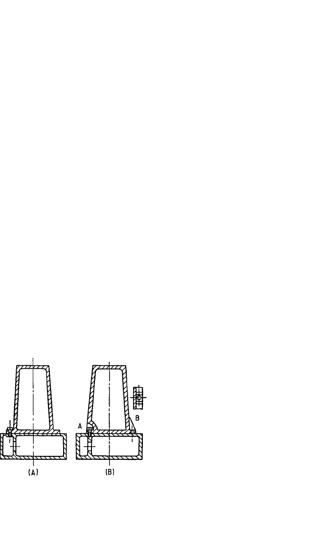
table, etc. Some points to be considered in the design of connections are illustrated in
Fig. 40.6.
13
To avoid bending of the flange in Fig. 40.6A, the bolts should be placed in
pockets or between ribs, as shown in Fig. 40.6B. Increasing the flange thickness does
not necessarily increase the stiffness of the
connection, since this requires longer bolts,
which are more flexible. There is an opti-
mum flange thickness (bolt length), the
value of which depends on the elastic
deformation in the vicinity of the connec-
tion. Deformation of the bed is minimized
by placing ribs under connecting bolts.
13
The efficiency of bolted connections,
and other static and dynamic structural
problems, is conveniently investigated by
scaled model analysis
13
and finite-element
analysis techniques described in Chap. 28,
Part II. Figure 40.7 shows the results of
successive stages of a model experiment in
which the effect of the design of bolt con-
nections on the bending rigidity (X and Y
directions) and the torsional rigidity of a
column were investigated. The relative
40.12 CHAPTER FORTY
FIGURE 40.6 Load transmission between
column and bed. (A) Old design, relatively
flexible owing to deformation of flange. (B)
New design, bolt placed in a pocket (A) or
flange stiffened with ribs on both sides of bolt
(B). (After H. Opitz.
13
)
8434_Harris_40_b.qxd 09/20/2001 12:23 PM Page 40.12
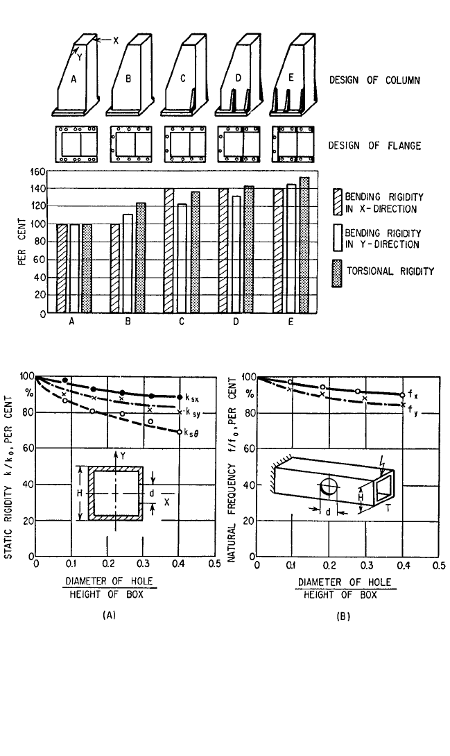
rigidities are shown by the length of bars. In the design of Fig. 40.7A, the connection
consists of 12 bolts (diameter of
5
⁄8 in.) arranged in pairs along both sides of the col-
umn. In the design of Fig. 40.7B, the number of bolts is reduced to 10, arranged as
shown.With the addition of ribs, shown in succeeding figures, the bending stiffness in
the direction X was raised by 40 percent, that in the direction Y by 45 percent, and the
torsional stiffness by 53 percent, compared to the original design.
13
MACHINE-TOOL VIBRATION 40.13
FIGURE 40.7 Successive stages in the improvement of a flange connection. (H. Opitz.
13
)
FIGURE 40.8 Influence of a hole in the wall of a box column on the static stiffness and natural fre-
quency. (A) Static stiffness; (B) natural frequency. (H. Opitz.
13
)
8434_Harris_40_b.qxd 09/20/2001 12:23 PM Page 40.13
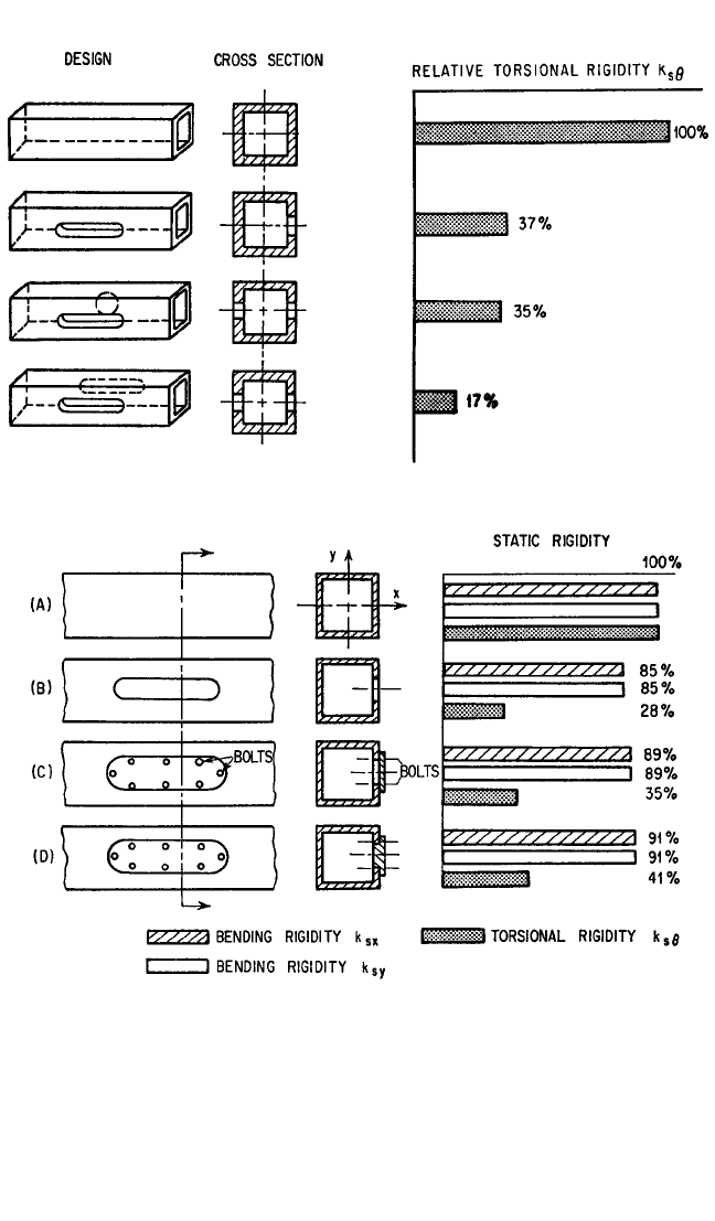
Openings in columns should be as small as possible. Figure 40.8 shows the loss of
static flexural stiffness k
sx
,k
sy
, and torsional stiffness k
sθ
, and the decrease of the flex-
ural natural frequencies f
x
,f
y
, resulting from the introduction of a hole in a box-type
column. Smaller holes result in relatively smaller decreases of stiffness and natural
frequency than larger ones. The torsional rigidity k
sθ
of a box-type column is partic-
ularly sensitive to openings, as shown in Fig. 40.9.
13
Lids or doors used for covering
40.14 CHAPTER FORTY
FIGURE 40.9 Torsional stiffness of box columns with different holes in walls. (H. Opitz.
13
)
FIGURE 40.10 Influence of cover plate and lid on static stiffness of box column. (A) Col-
umn without holes, (B) one hole uncovered, (C) hole covered with cover plate, and (D) hole
covered with substantial lid, firmly attached. (After H. Opitz.
13
)
8434_Harris_40_b.qxd 09/20/2001 12:23 PM Page 40.14

these openings do not restore the stiffness. The influence of covers depends on their
thickness, mode of attachment, and design, as shown in Fig. 40.10.
13
However, covers
may increase damping and thereby partly compensate for the detrimental effect of
loss of stiffness.
Welded structural components are usually stiffer than cast iron components but
have a lower damping capacity. Some damping is generated because welds are never
perfect; consequently, rubbing takes place between joined members. A considerable
increase in damping can be achieved by using interrupted welds, but at a price of
reduced stiffness. Welded ribs may be necessary not so much to increase rigidity as
to prevent “drumming” (membrane vibration) of large unsupported areas.
Not all deformations in machine tools are objectionable, but only those which
influence relative displacements in the work zone between the tool and the work-
piece. The magnitude of the relative displacement in the work zone under external
or internal forces (weight, cutting force, inertia force) determines effective stiffness.
Effective stiffness of machine-tool frames is significantly influenced by their
interaction with the supporting structures (foundations). For large, low-aspect-
ratio machine-tool frames, a rigid attachment to a properly dimensioned
6
founda-
tion substantially improves dynamic stability. Medium- and small-size machine
tools are usually attached to the reinforced floor plate by discrete mounts (rigid
wedge or screw mounts or vibration isolators). A rational assignment of number
and location of mounts noticeably enhances the effective stiffness of machine
tools and in some cases may allow direct mounting of rather large machine tools
on vibration isolators. Examples of influence of number and location of mounts on
the effective stiffness are given in Fig. 40.11, which shows three schematics of a
mounting for a jig borer on rigid wedge mounts. The table of the jig borer is in the
lower end of the illustration. Relative displacements in the work zone when the
table travels from right to left for the scheme in Fig. 40.11C are three times smaller
than for Fig. 40.11A and 1.5 times smaller than for Fig. 40.11B, notwithstanding the
fact that in the latter case there are seven mounts vs. three mounts in Fig. 40.11C.
In the case shown in Fig. 40.11A, the large weight of the moving table creates a
twisting of the supporting frame about the single front mount, while the column is
rigidly positioned by two mounts. In case of Fig. 40.11C, the front end is well sup-
ported, but the column can tilt on its single mount and follow small deformations
of the front part, thus resulting in smaller relative deformations and higher effec-
tive stiffness. For example, in the case of a precision grinder having a bed 3.8 m
long, it was found that mounting the grinder on seven carefully located (offset
from the ends) vibration isolators resulted in higher effective stiffness than instal-
lation on 15 rigid mounts.
3
The effective static stiffness of a machine tool may vary within wide limits. High
stiffness values are ensured by the use of steady rests, by placing tool and workpiece
in a position where the relative dynamic displacement between them is small (i.e., by
MACHINE-TOOL VIBRATION 40.15
12
3 21
3
FIGURE 40.11 Mounting schemes of a jig borer. (After V.
Kaminskaya from Ref. 6.)
8434_Harris_40_b.qxd 09/20/2001 12:23 PM Page 40.15
placing them near the main column, etc.), by using rigid tools and clamps, by using
jigs which rigidly clamp (and if necessary support) the workpiece, by clamping
securely all parts of the machine which do not move with respect to each other, etc.,
and by the optimization of mounting conditions mentioned above.
The static and dynamic behavior of machine tools is influenced significantly by
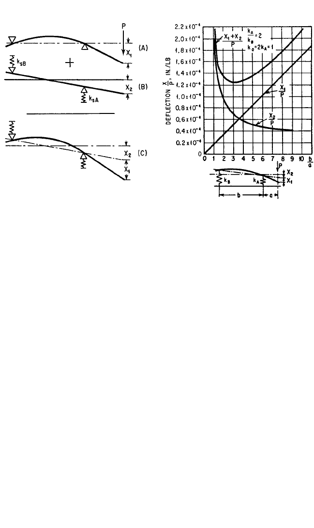
the design of the spindle and its bearings.The static deflection of the spindle consists
of two parts, X
1
and X
2
, as shown in Fig. 40.12. The deflection X
1
corresponds to the
deflection of a flexible beam on rigid supports, and X
2
corresponds to the deflection
of a rigid beam on flexible supports which represent the flexibility of the bearings.
The deflection of the spindle amounts to 50 to 70 percent of the total deflection, and
the bearings 30 to 50 percent of the total, depending on the relation of spindle cross
section to bearing stiffness and span. The stiffness of antifriction bearings depends
on their design, accuracy, preload, and the fit between the outer race and the hous-
ing (responsible for 10 to 40 percent of the bearing deformation
3
).
The distance between the bearings has considerable influence on the effective
stiffness of the spindle, as shown in Fig. 40.13. The ordinate of the figure corresponds
to the deflection in inches per pound, and the abscissa represents the ratio of bear-
ing distance b to cantilever length a. The straight line refers to the deflection of the
spindle, and the hyperbola refers to the deflection of the bearings. The total deflec-
tion is obtained by the addition of the two curves; the minimum of the curve of total
deflection corresponds to the optimum bearing distance. For a short cantilever
length a, the optimum value of b/a lies between 3 and 5; for a long cantilever length
a, the optimum b/a =∼2.
It is often important to consider the dynamic behavior of a spindle before estab-
lishing an optimum bearing span. Maximizing the stiffness of a spindle at one point
does not establish its dynamic properties. Care must be taken to investigate both
bending and rocking modes of the spindle before accepting a final optimum span.
40.16 CHAPTER FORTY
FIGURE 40.12 Deflection of machine-tool
spindle and bearings. A machine-tool spindle
can be regarded as a beam on flexible supports.
The total deflection under the force P consists of
the sum of (A) the deflection X
1
of a flexible
beam on rigid supports and (B) the deflection X
2
of a rigid beam on flexible supports. (H. Opitz.
13
)
FIGURE 40.13 Deflection of a beam on elas-
tic supports as a function of the bearing distance.
Bearing stiffness k
A
and k
B
, spindle stiffness k
o
.
(After H. Opitz.
13
)
8434_Harris_40_b.qxd 09/20/2001 12:23 PM Page 40.16
For example, a large overhang on the rear of a spindle could produce an undesirable
low-frequency rocking mode of the spindle even if the “optimum span” as defined
previously were satisfied.The optimum bearing span for minimum deflection as well
as the dynamic characteristics of spindles may be computed with the help of avail-
able computer programs.
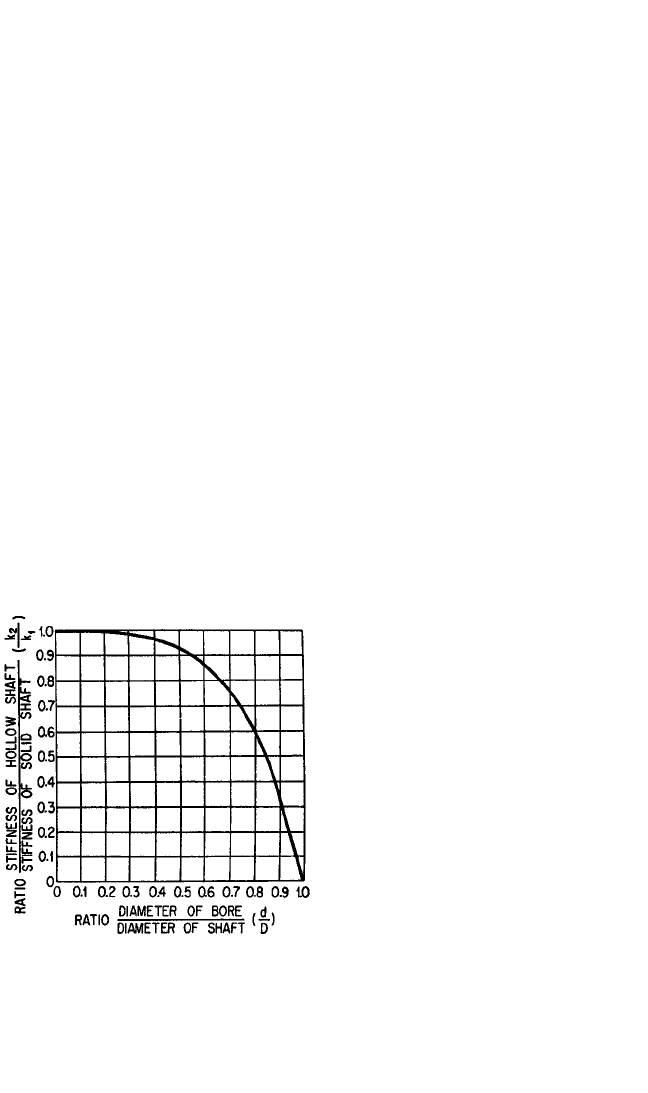
The influence of the ratio of bore diameter to outside diameter on the stiffness of
a hollow spindle is shown in Fig. 40.14.
13
A 25 percent decrease in stiffness occurs
only at a diameter ratio of d/D = 0.7, where D is the outside diameter and d the bore
diameter. This is important for the dynamic behavior of the spindle. A solid spindle
has nearly the same stiffness, but a substantially greater mass. Consequently, the nat-
ural frequency of the solid spindle is considerably lower, which is undesirable.A stiff
spindle does not always assure the required high stiffness at the cutting edge of the
tool because of potentially large contact deformations in the toolholder/spindle
interface. Measurements have shown that in a tapered connection, these deforma-
tions may constitute up to 50 percent of the total deflection at the tool edge.
3
These
deformations can be significantly reduced by replacing tapered connections by face
contact between the toolholder and the spindle. The face connection must be loaded
by a high axial force.
12
A significant role (frequently up to 50 percent) in the breakdown of deforma-
tions between various parts of machine tool structures is played by contact defor-
mations between conforming (usually flat, cylindrical, or tapered) contacting
surfaces in structural joints and slides.
3,14
Contact deformations are due to surface
imperfections on contacting surfaces. These deformations are highly nonlinear and
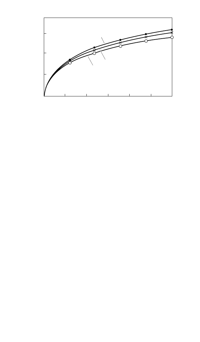
are influenced by lubrication conditions. Figure 40.15 shows contact deformation
between flat steel parts as a function of contact pressure for different lubrication
conditions in the joint. Joints are also responsible for at least 90 percent of structural
damping in machine-tool frames due to
micromotions in the joints during vibra-
tory processes. Contact deformations
for the same contact pressure can be sig-
nificantly reduced by increasing accu-
racy (fit) and improving the surface
finish of the mating surfaces. The non-
linear load-deflection characteristic of
joints, Fig. 40.15, allows enhancement of
their stiffness by preloading. However,
preloading reduces micromotions in
the joints and thus results in a lower
damping.
This explains why in some cases old
machines are less likely to chatter than
new machines of identical design. The
situation may result from wear and tear
of the slides, which increases the damp-
ing and effects an improvement in per-
formance. Also, in some cases chatter is
eliminated by loosening the locks of
slides. However, it would be wrong to
conclude that lack of proper attention
and maintenance is desirable. Proper
attention to slides, bearings (minimum
play), belts, etc., is necessary for satisfac-
MACHINE-TOOL VIBRATION 40.17
FIGURE 40.14 Effect of bore diameter on
stiffness of hollow spindle where k
1
= stiffness of
solid spindle, k
2
= stiffness of hollow spindle, D =
outer spindle diameter, d = bore diameter, J
2
=
second moment of area of hollow spindle, and J
1
= second moment of area of solid spindle. The
curve is defined by k
2
/k
1
= J
2
/J
1
= 1 − (d/D).
4
(H.
Opitz.
13
)
8434_Harris_40_b.qxd 09/20/2001 12:23 PM Page 40.17
tory performance. It would be wrong also to conclude that a highly polluted work-
shop atmosphere is desirable because some new machines exposed to workshop dirt
for a sufficiently long time, even when not used, appear to improve in their chatter
behavior.The explanation is that dirty slides increase the damping.
When the rigidity of some machine element is intentionally reduced, but this
reduction is accompanied by a greater damping at the cutter, the increase in damp-
ing may outweigh the reduction in rigidity.
3
Although a loss of rigidity in machine
tools is generally undesirable, it may be tolerated when it leads to a desirable shift in
natural frequencies or is accompanied by a large increase in damping or by a bene-
ficial change in the ratio of stiffnesses along two orthogonal axes, which can result in
improved nonregenerative chatter stability.
8
A very significant improvement in chatter resistance can be achieved by an inten-
tional measured reduction of stiffness in the direction along the cutting speed
(orthogonal to the direction of the principal component of cutting force). The bene-
fits of this approach have been demonstrated for turning and boring operations.
12,15
DAMPING
The overall damping capacity of a structure with cast iron or welded steel frame com-
ponents is determined only to a small extent by the damping capacity of its individual
components. The major part of the damping results from the interaction of joined
components at slides or bolted joints.
3,14
The interaction of the structure with the
foundation or highly damped vibration isolators also may produce a noticeable
damping.
3,8
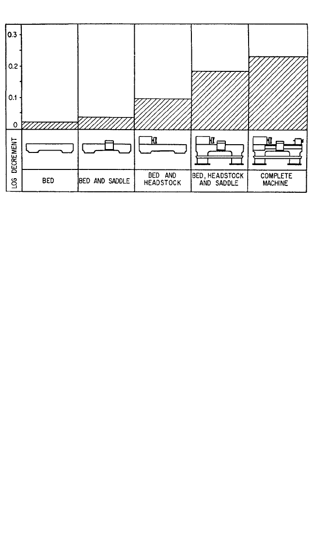
A qualitative picture of the influence of the various components of a lathe
on the total damping is given in Fig. 40.16.The damping of the various modes of vibra-
tion differs appreciably; the values of the logarithmic decrement shown in the figure
correspond to an average value for all the modes which play a significant part.
The overall damping of various types of machine tool differs, but the log decre-
ment is usually in the range of from 0.15 to 0.3. While structural damping is signifi-
cantly higher for frame components made of polymer-concrete compositions or
40.18 CHAPTER FORTY
JOINT DEFORMATION (µm)
AVERAGE CONTACT PRESSURE (MPa)
1
2
3
0.2 0.4 0.6 0.8 1.0
6
4
2
0
FIGURE 40.15 Load-deflection characteristics for flat, deeply scraped
surfaces (overall contact area 80 cm
2
). 1, no lubrication; 2, lightly lubricated
(oil content 0.8 × 10
−3
gram/cm
2
); 3, richly lubricated (oil content 1.8 × 10
−3
gram/cm
2
). (After Z. Levina and D. Reshetov.
14
)
8434_Harris_40_b.qxd 09/20/2001 12:23 PM Page 40.18
granite (see above), the overall damping does not change very significantly since the
damping of even these materials is small compared with damping from joints.
A significant damping increase can be achieved by filling internal cavities of the
frame parts with a granular material, e.g., sand. For cast parts it can also be achieved
by leaving cores in blind holes inside the casting. A similar, sometimes even more
pronounced, damping enhancement can be achieved by placing auxiliary longitudi-
nal structural members inside longitudinal cavities within a frame part, with offset
from the bending neutral axis of the latter.The auxiliary structural member interacts
with the frame part via a high viscous layer, thus imparting energy dissipation during
vibrations.
Damping can be increased without impairing the static stiffness and machining
accuracy of the machine by the use of dampers and dynamic vibration absorbers.
These are basically similar to those employed in other fields of vibration control
(Chaps. 6, 32, and 41). Dampers are effective only when placed in a position where
vibration amplitudes are significant.
The tuned dynamic vibration absorber (Chap. 6) has been employed with consid-
erable success on milling machines, machining centers, radial drilling machines, gear
hobbing machines, grinding machines, and boring bars.
15,17
A design variant of this
type of absorber is shown in Fig. 40.17. In this design a plastic ring element combines
both the elastic and the damping elements of the absorber. The auxiliary mass may
be attached to the top of a column (Fig. 40.17C), as shown in Fig. 40.17A. Alterna-
tively, the auxiliary mass may be suspended on the underside of a table (Fig. 40.17C),
using the design shown in Fig. 40.17B. In either case, several plastic ring elements
may support one large auxiliary mass, as shown in Fig. 40.17C. In a boring bar, shown
in Fig. 40.18A, elastic and damping properties are combined in O-rings made of a
high-damping rubber. Tuning of the absorber can be changed by varying the radial
preload force on the O-ring. The natural frequency of this absorber can be varied
over a range of more than 3:1.
A variation of the Lanchester damper (Chap. 6) is frequently used in boring bars
to good advantage.
16
This consists of an inertia weight fitted into a hole bored in the
end of a quill. To ensure effective operation, a relatively small radial clearance of
MACHINE-TOOL VIBRATION 40.19
FIGURE 40.16 Influence of various components on total damping of lathes. The major part of
the damping is generated at the mating surfaces of the various components. (K. Loewenfeld.
16
)
8434_Harris_40_b.qxd 09/20/2001 12:23 PM Page 40.19
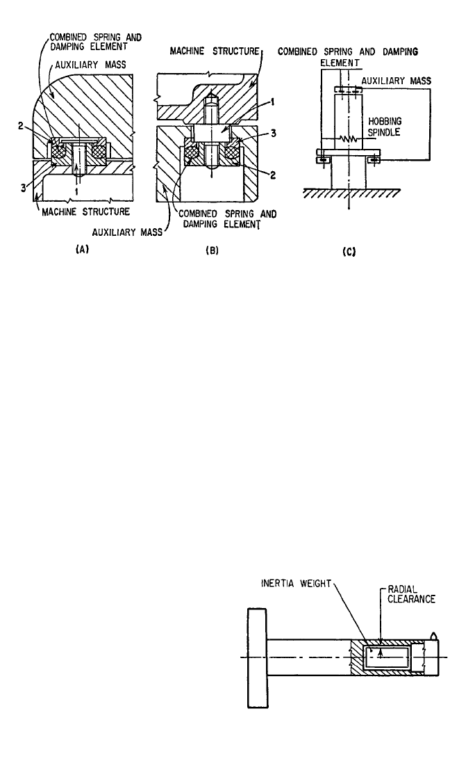
about 1 to 5 × 10
−3
d must be provided, where d is the diameter of the inertia weight.
An axial clearance of about 0.006 to 0.010 in. (0.15 to 0.25 mm) is sufficient. A
smooth surface finish of both plug and hole is desirable. The clearance values given
refer to dry operation, using air as the damping medium. Oil also can be used as a
damping medium, but it does not necessarily result in improved performance.When
applying oil, clearance gaps larger than those stated above have to be ensured,
depending on the viscosity of the oil. In general, Lanchester dampers are less effec-
tive than tuned vibration absorbers.
Since the effectiveness of both Lanchester dampers and tuned vibration
absorbers depends on the mass ratio between the inertia mass and the effective mass
of the structure (Chap. 6), heavy materials such as lead and, especially, machinable
sintered tungsten alloys are used for inertia masses in cases where the dimensions of
the inertia mass are limited (as in the case of boring bars in Fig. 40.18). The mass
ratio and the effectiveness of the absorber can be significantly enhanced by using a
combination structure. In such a struc-
ture the overhang segment of the boring
bar or other cantilever structure, which
does not significantly influence its stiff-
ness but determines its effective mass, is
made of a light material, while the root
segment, which determines the stiffness
but does not significantly influence the
effective mass, is made from a high
Young’s modulus material.
15
Dynamic absorbers can be active
(servo-controlled). Such devices can be
designed to be self-optimizing (capable
of self-adjustment of the spring rate to
minimize vibration amplitude under
40.20 CHAPTER FORTY
FIGURE 40.17 Auxiliary mass damper with combined elastic and damping element. The
combined element lies between two retainer rings, of which one (3) is attached with bolt 1 to
the machine structure. The other ring (2) takes the weight of the auxiliary mass. (A) Arrange-
ment when auxiliary mass is being supported. (B) Arrangement when auxiliary mass is being
suspended. (C) Application of both types of arrangements to a hobbing machine. (After
F. Eisele and H. W. Lysen.
17
)
FIGURE 40.18 Lanchester damper for the
suppression of boring bar vibration. (After R. S.
Hahn.
18
)
8434_Harris_40_b.qxd 09/20/2001 12:23 PM Page 40.20

changing excitation conditions) or to use a vibration cancellation approach.The self-
optimizing feature is achieved by placing vibration transducers on both the absorber
mass and the main system. A control circuit measures the phase angle between the
motions and activates a spring-modifying mechanism to maintain a 90° phase differ-
ence between the two measured motions. It has been demonstrated that the 90°
phase relationship guarantees minimum motion of the main vibrating mass. In the
vibration-cancellation devices, the actuator applies force to the structure which is
opposite in phase to structural vibrations.
Dynamic analysis of a machine tool structure can identify potentially unstable
natural modes of vibration and check the effectiveness of the applied treatments. In
another approach, transfer functions between the selected points on the machine
tool are measured and processed through a computational technique which indi-
cates at which location stiffness and/or damping should be modified or a dynamic
vibration absorber installed in order to achieve specified dynamic characteristics of
the machine tools.
3
Tool Design. Sharp tools are more likely to chatter than slightly blunted tools. In
the workshop, the cutting edge is often deliberately dulled by a slight honing. Con-
sequently, a beveling of the leading face of a lathe tool has been suggested. This
bevel has a leading edge of −80° and a width of about 0.080 in. (0.2 mm). Tests show
that the negative bevel does not in all cases eliminate vibration and that the life of
the bevel is short. Appreciably worn cutting edges cause violent chatter.
Since narrow chips are less likely to lead to instability, a reduction of the
approach angle of the cutting tool results in improved chatter behavior. With lathe
tools, an increase in the rake angle may result in improvement, but the influence of
changes in the relief angle is relatively small.
Reduction of both forced and chatter vibrations in cutting with tools having mul-
tiple cutting edges (e.g., milling cutters, reamers) can be achieved by making the dis-
tance between the adjacent cutting edges nonequal and/or making the helix angle of
the cutting edges different for each cutting edge. However, such treatment results in
nonuniform loading of the cutting edges and may lead to a shortened life of the
more heavily loaded edges as well as deteriorating surface finish as a result of dif-
ferent deformations of the tool when lighter or heavier loaded edges are engaged.
Reduction of cutting forces by low-friction (e.g., diamond) coating of the tool or
by application of ultrasonic vibrations to the tool usually improves chatter resistance.
Variation of Cutting Conditions. In the elimination of chatter, cutting condi-
tions are first altered. In some cases of regenerative chatter, a small increase or
decrease in speed may stabilize the cutting process. In high-speed or unattended
computer numerically controlled machine tools, this can be achieved by continuous
computer monitoring of vibratory conditions and, as chatter begins to develop, a
shifting of the spindle rpm toward the stable area.
Cutting with a variable cutting speed (constant speed modulated by a sinusoidal
or other oscillatory component) acts similarly with regard to undulations in the posi-
tioning of the cutting edges (see above) and results in increased chatter resistance.
The dots in Fig. 40.5 show the stabilizing effect of the sinusoidal modulation of the
cutting speed.
11
An increase in the feed rate is also beneficial in some types of machining
(drilling, face milling, and the like). For the same cross-sectional area, narrow chips
(high feed rate) are less likely to lead to chatter than wide chips (low feed rate),
since the chip thickness variation effect results in a relatively smaller variation of the
cross-sectional area in the former (smaller dynamic cutting force).
MACHINE-TOOL VIBRATION 40.21
8434_Harris_40_b.qxd 09/20/2001 12:23 PM Page 40.21
