Halderman J.D., Linder J. Automotive Fuel and Emissions Control Systems
Подождите немного. Документ загружается.

CATALYTIC CONVERTERS 351
STEP BY STEP
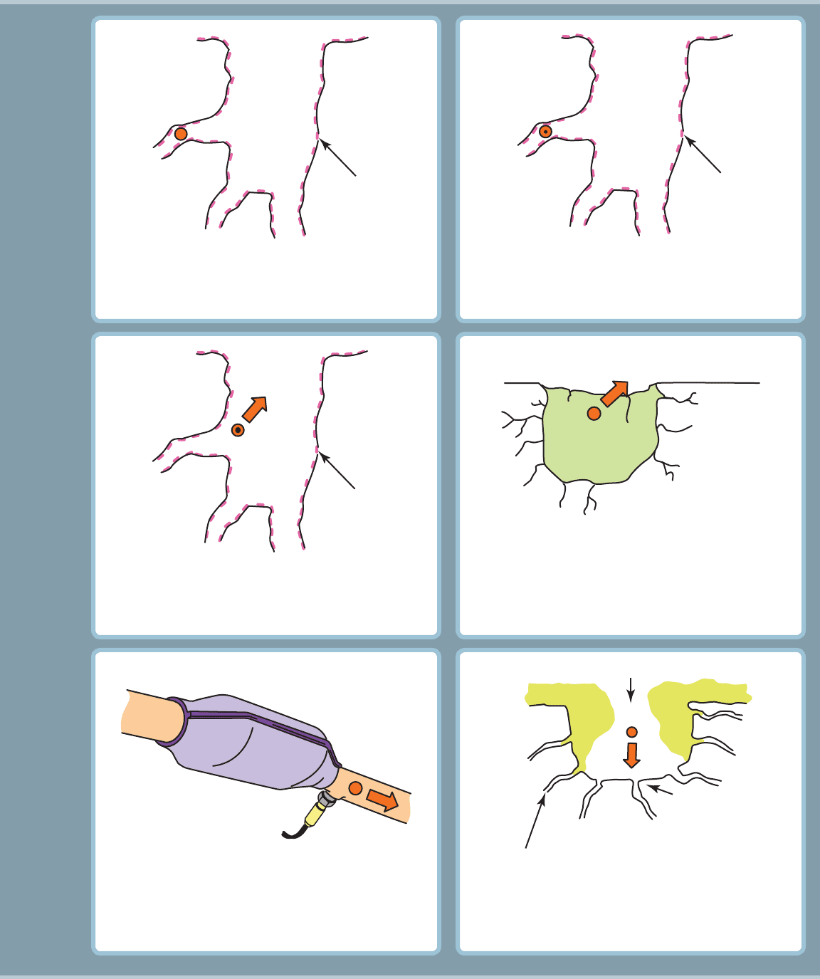
The CO molecule is absorbed onto a catalyst side. Only
a few grams of catalyst material are applied to the
washcoat.
7
The CO molecule is converted to a CO
2
molecule.
8
The CO
2
molecule is exiting the small micropore.
9
The CO
2
molecule is exiting the larger micropore.
10
The CO
2
molecule is exiting the converter.
11
A poisoned converter.
12
CATALYST
MATERIAL
CO
2
CATALYST
MATERIAL
CO
2
CATALYST
MATERIAL
MICROPORE
POISON
MACROPORE
POISON
POROUS
WASHCOAT

352 CHAPTER 28
5. A catalytic converter has to be over 500°F (260°C) before
it starts to become effective and is therefore mounted as
close as possible to the exhaust parts of the engine.
6. The OBD-II system monitor compares the relative activity
of a rear oxygen sensor to the precatalytic oxygen sensor
to determine catalytic converter efficiency.
7. Catalytic converters can be tested for restriction and for
efficiency.
1. A catalytic converter is an after treatment device that
reduces exhaust emissions outside of the engine.
2. The honeycomb shape of the catalytic converter is con-
structed of a ceramic material about 0.006 inch thick with
small square openings.
3. A catalyst is an element that starts a chemical reaction but
is not consumed in the process.
4. The catalyst materials used in a catalytic converter include
rhodium, palladium, and platinum.
SUMMARY
4. How does the computer monitor catalytic converter
performance?
5. What tests can be performed by a service technician to
test the catalytic converter?
1. What are the three most commonly used catalysts in a
catalytic converter?
2. How does a catalytic converter reduce NO
x
to nitrogen and
oxygen?
3. Why must a catalytic converter be mounted close to the
exhaust ports of the engine?
REVIEW QUESTIONS
5. A catalytic converter can be harmed by ______________ .
a. Excessive engine oil
b. Antifreeze
c. Sulfur from poor-quality fuel
d. Any of the above
6. Two technicians are discussing testing a catalytic con-
verter. Technician A says that a vacuum gauge can be
used and observed to see if the vacuum drops with the
engine at 2,500 RPM for 60 seconds. Technician B says
that a pressure gauge can be used to check for back pres-
sure. Which technician is correct?
a. Technician A only
b. Technician B only
c. Both Technicians A and B
d. Neither Technician A nor B
7. A catalytic converter is being tested with an infrared py-
rometer. Which is an acceptable (good converter) result?
a. The inlet should be hotter than the outlet by 10%.
b. The outlet should be hotter than the inlet by 10%.
c. Both the inlet and the outlet should be the same
temperature after the converter reaches operating
temperature.
d. The temperature of a catalytic converter is the best
test to perform to locate a restricted (clogged) unit.
1. What is applied to the ceramic substrate to make the sur-
face porous?
a. Honeycomb filler
b. Washcoat
c. Aluminum
d. Cerium
2. Two technicians are discussing catalytic converters. Tech-
nician A says that the exhaust mixture must fluctuate
between rich and lean for the best efficiency. Technician
B says that the air-fuel mixture must be leaner than 14.7:1
for best performance from a three-way catalytic converter.
Which technician is correct?
a. Technician A only
b. Technician B only
c. Both Technicians A and B
d. Neither Technician A nor B
3. A catalytic converter has to be at least how hot before it
starts to work?
a. 500°F (260°C)
b. 1,000°F (540°C)
c. 1,500°F (815°C)
d. 2,000°F (1,100°C)
4. What two primary sensors does the PCM use to check the
catalytic converter?
a. Catalytic converter temperature sensor and rear
oxygen sensor
b. Precat and postcat oxygen sensor
c. Precat oxygen sensor and MAF
d. MAP and TP
CHAPTER QUIZ

CATALYTIC CONVERTERS 353
10. Technician A says that the catalytic converter is warranted
for eight years or 80,000 miles, whichever comes first.
Technician B says that after replacing the catalytic con-
verter, the old converter must be kept for possible inspec-
tion for 60 days. Which technician is correct?
a. Technician A only
b. Technician B only
c. Both Technicians A and B
d. Neither Technician A nor B
8. Which exhaust gas reading indicates a good catalytic
converter?
a. O
2
is zero c. Both a and b
b. CO is zero d. Neither a nor b
9. A P0422 (catalytic converter efficiency failure) is set. What
is a possible cause?
a. Engine mechanical fault
b. Exhaust leak
c. Fuel contamination
d. Any of the above
354 CHAPTER 29
chapter
IGNITION SYSTEM
OPERATION
AND DIAGNOSIS
29
OBJECTIVES: After studying Chapter 29 , the reader should be able to: • Prepare for ASE Engine Performance (A8)
certification test content area “B” (Ignition System Diagnosis and Repair). • Explain how ignition coils create 40,000 volts or
more. • Discuss crankshaft position sensor and pickup coil operation. • Describe the operation of waste-spark
and coil-on-plug (COP) ignition systems. • Describe how to test ignition coils. • Explain how to test spark plug wire.
• Describe the test procedure for the diagnosis and repair of electronic ignition systems. • Explain how to inspect
and replace spark plugs. • Discuss what to inspect and look for during a visual inspection of the ignition system. • List the
steps necessary to check and/or adjust ignition timing on engines equipped with a distributor-type ignition system.
KEY TERMS: Coil-on-plug (COP) ignition 355 • Companion cylinders 361 • Detonation 365 • Distributor ignition 355
• Electronic ignition 355 • EMI 355 • Firing order 360 • Hall effect 357 • ICM 356 • Ignition coil 355 • Ignition
timing 375 • Ion-sensing ignition 365 • Iridium spark plugs 372 • Knock sensors 365 • Magnetic pulse generator 357
• Pickup coil 357
• Ping 365 • Platinum spark plugs 372 • Primary ignition circuit 356 • Primary winding 355 • Schmitt
trigger 358 • Secondary ignition circuit 356 • Secondary winding 355 • Spark knock 365
• Spark plugs 372 • Spark
tester 367 • Switching 356 • Track 370 • Transistor 357 • Trigger 357 • Turns ratio 355 • Waste-spark system 355
PURPOSE AND FUNCTION The ignition system includes
components and wiring necessary to create and distribute a high
voltage (up to 40,000 volts or more) and send to the spark plug.
Ahigh-voltage arc occurs across the gap of a spark plug at the
right time inside the combustion chamber. The spark raises the
temperature of the air-fuel mixture and starts the combustion
process inside the cylinder.
BACKGROUND All ignition systems apply battery voltage
(close to 12 volts) to the positive side of the ignition coil(s) and
pulse the negative side to ground:
Early ignition systems. Before the mid-1970s, ignition
systems used a mechanically opened set of contact
points to make and break the electrical connection to
ground. Acam lobe, located in and driven by the distribu-
tor, opened the points. There was one lobe for each cylin-
der. The points used a rubbing block that was lubricated
by applying a thin layer of grease on the cam lobe at
each service interval. Each time the points opened, a high
voltage was created in the ignition coil. The high-voltage
then traveled to each spark plug through the distributor
cap and rotor. The distributor was used twice in the
creation of the spark, as follows:
IGNITION SYSTEM
POINTS
DISTRIBUTOR
CAM
CONDENSER
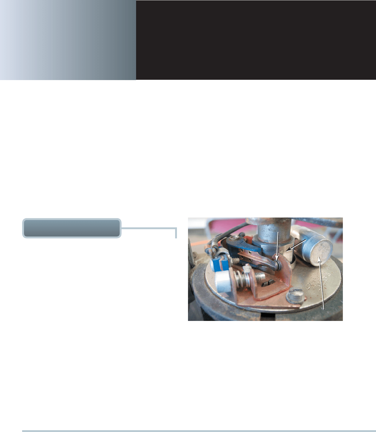
FIGURE 29–1 A point-type distributor from a hot rod.
1. It was connected to the camshaft which rotated the
distributor cam, causing the points to open and close.
2. It used a rotor to send the high-voltage from the coil
entering the center of the distributor cap to inserts
connected to spark plug wires to each cylinder.
SEE FIGURE 29–1 .
Electronic ignition. Since the mid-1970s, ignition sys-
tems have used sensors, such as a pickup coil and
reluctor (trigger wheel), to trigger or signal an electronic
module that switches the primary ground circuit of the
IGNITION SYSTEM OPERATION AND DIAGNOSIS 355
ignition coil. Distributor ignition is the term specified by
the Society of Automotive Engineers (SAE) for an ignition
system that uses a distributor. Electronic ignition is the
term specified by the SAE for an ignition system that does
not use a distributor. Electronic ignition system types
include the following:
1. Waste-spark system. This type of system uses one
ignition coil to fire the spark plugs for two cylinders at
the same time.
2. Coil-on-plug (COP) system. This type of system uses
a single ignition coil for each cylinder with the coil
placed above or near the spark plug.
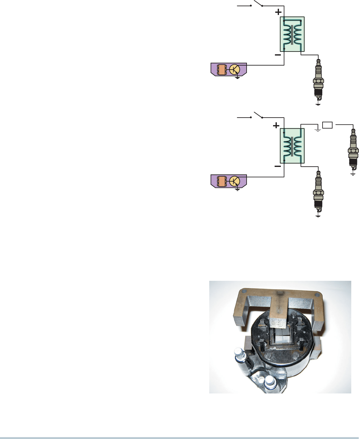
IGNITION COIL CONSTRUCTION The heart of any igni-
tion system is the ignition coil. When the coil negative lead is
grounded, the primary (low-voltage) circuit of the coil is com-
plete, and a magnetic field is created around the coil windings.
When the circuit is opened, the magnetic field collapses and
induces a high voltage in the secondary winding of the igni-
tioncoil.
The coil creates a high-voltage spark by electromagnetic
induction. Many ignition coils contain two separate but electri-
cally connected windings of copper wire. Other coils are true
transformers in which the primary and secondary windings are
not electrically connected.
SEE FIGURE 29–2 .
The center of an ignition coil contains a core of laminated
soft iron (thin strips of soft iron). This core increases the mag-
netic strength of the coil:
Secondary coil winding. Surrounding the laminated
core are approximately 20,000 turns of fine wire (approxi-
mately 42 gauge). The winding is called the secondary
winding.
Primary coil winding. Surrounding the secondary
windings are approximately 150 turns of heavy wire
(approximately 21 gauge). The winding is called the
primary winding. The secondary winding has about
100times the number of turns of the primary winding,
referred to as the turns ratio (approximately 100:1).
In older coils, these windings are surrounded with a thin
metal shield and insulating paper and placed into a metal
container filled with transformer oil to help cool the coil wind-
ings. Other coil designs use an air-cooled, epoxy-sealed
E coil. The E coil is so named because the laminated, soft iron
core is E shaped, with the coil wire turns wrapped around
the center “finger” of the E and the primary winding wrapped
inside the secondary winding.
SEE FIGURES 29–3
AND 29–4.
IGNITION COIL OPERATION All ignition systems use
electromagnetic induction to produce a high-voltage spark from
the ignition coil. Electromagnetic induction (EMI) means that
a current can be created in a conductor (coil winding) by a
moving magnetic field. The magnetic field in an ignition coil is
produced by current flowing through the primary winding of
BATTERY (B+)
IGNITION
SWITCH
IGNITION
SWITCH
PRIMARY
SECONDARY
COIL
IGNITION
MODULE
SPARK
PLUG
BATTERY (B+)
PRIMARY
SECONDARY
COIL
IGNITION
MODULE
SPARK
PLUG
OR
SPARK
PLUG
FIGURE 29–2 Some ignition coils are electrically connected,
called married (top figure), whereas others use separate pri-
mary and secondary windings, called divorced (lower figure).
The polarity (positive or negative) of a coil is determined by the
direction in which the coil is wound.
FIGURE 29–3 The steel lamination used in an E coil helps
increase the magnetic field strength, which helps the coil pro-
duce higher energy output for a more complete combustion in
the cylinders.
356 CHAPTER 29
the coil. An ignition coil is able to increase battery voltage to
40,000 volts or more in the following way:
Battery voltage is applied to the primary winding.
A ground is provided to the primary winding by the
ignition control module (ICM), igniter, or PCM.
Current (approximately 2 to 6 amperes) flows in the primary
coil creating a magnetic field in the primary winding.
When the ground is opened by the ICM, the built-up
magnetic field collapses.
The movement of the collapsing magnetic field
induces a voltage of 250 to 400 volts in the primary
winding and 20,000 to 40,000 volts or more in the
secondary winding with a current of 0.020 to
0.080ampere.
The high voltage created in the secondary winding is high
enough to jump the air gap at the spark plug.
The electrical arc at the spark plug ignites the air-fuel
mixture in the combustion chamber of the engine.
For each spark that occurs, the coil must be charged with
a magnetic field and then discharged.
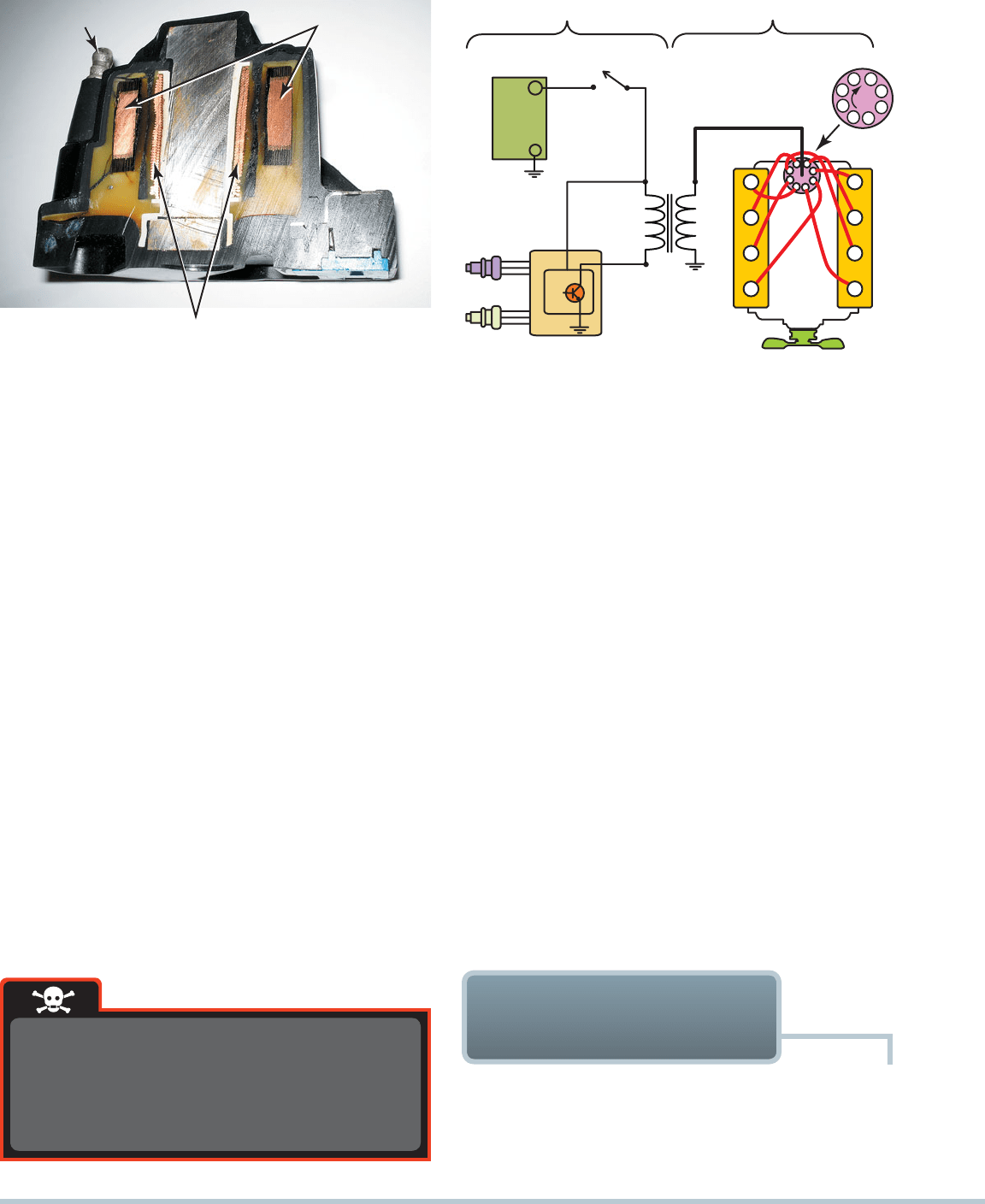
SECONDARY
TERMINAL
PRIMARY
WINDING
SECONDARY
WINDING
FIGURE 29–4 The primary windings are inside the secondary
windings on this General Motors coil.
3
5
1
4
6
2
7
8
1
2
3
4
5
6
7
8
ICM
SECONDARY
PRIMARY
IGNITION
SWITCH
COIL
CMP
SENSOR
CKP
SENSOR
PCM
FIGURE 29–5 The primary ignition system is used to trigger
and therefore create the secondary (high-voltage) spark from
the ignition coil.
The spark from an ignition coil is strong enough
to cause physical injury. Always follow the exact
service procedure and avoid placing hands near
the secondary ignition components when the
engine is running.
WARNING
The ignition components that regulate the current in the
coil primary winding by turning it on and off are known collec-
tively as the primary ignition circuit. When the primary circuit
is carrying current, the secondary circuit is off. When the pri-
mary circuit is turned off, the secondary circuit has high volt-
age. The components necessary to create and distribute the
high voltage produced in the secondary windings of the coil are
called the secondary ignition circuit.
SEE FIGURE 29–5 .
These circuits include the following components:
Primary ignition circuit
1. Battery
2. Ignition switch
3. Primary windings of coil
4. Pickup coil (crankshaft position sensor)
5. Ignition control module (igniter)
Secondary ignition circuit
1. Secondary windings of coil
2. Distributor cap and rotor (if the vehicle is so equipped)
3. Spark plug wires
4. Spark plugs
IGNITION SWITCHING
AND TRIGGERING
SWITCHING For any ignition system to function, the primary
current must be turned on to charge the coil and off to allow the
coil to discharge, creating a high-voltage spark. This turning on
and off of the primary circuit is called switching. The unit that does
IGNITION SYSTEM OPERATION AND DIAGNOSIS 357
NARROW GAP
RESULTS IN
STRONG MAGNETIC
FIELD FOR COIL
ROTATING FERROUS
METAL RELUCTOR
PERMANENT
MAGNET
WIDE GAP
OFFERS WEAK
MAGNETIC
FIELD FOR
COIL
PERMANENT
MAGNET
VOLTAGE REVERSES AS STAR WHEEL
MOVES PAST CLOSEST POINT
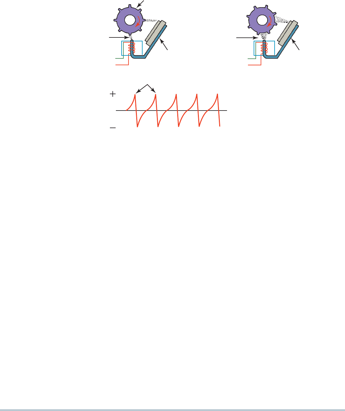
0
FIGURE 29–6 Operation of a typical pulse generator (pickup coil). At the bottom is a line drawing of a typical scope pattern
ofthe output voltage of a pickup coil. The module receives this voltage from the pickup coil and opens the ground circuit to the
ignition coil when the voltage starts down from its peak (just as the reluctor teeth start moving away from the pickup coil).
triggers the transistor inside the module and is also used by
the PCM for piston position information and engine speed
(RPM). The reluctor is shaped so that the magnetic strength
changes enough to create a usable varying signal for use by
the module to trigger the coil.
SEE FIGURE 29–6 .
Magnetic crankshaft position sensors use the changing
strength of the magnetic field surrounding a coil of wire to
signal the module and computer. This signal is used by the
electronics in the module and computer to determine piston
position and engine speed (RPM). This sensor operates simi-
larly to the distributor magnetic pickup coil. The crankshaft
position sensor uses the strength of the magnetic field sur-
rounding a coil of wire to signal the ICM. The rotating crank-
shaft has notches cut into it that trigger the magnetic position
sensor, which change the strength of the magnetic field as the
notches pass by the position sensor.
SEE FIGURE 29–7 .
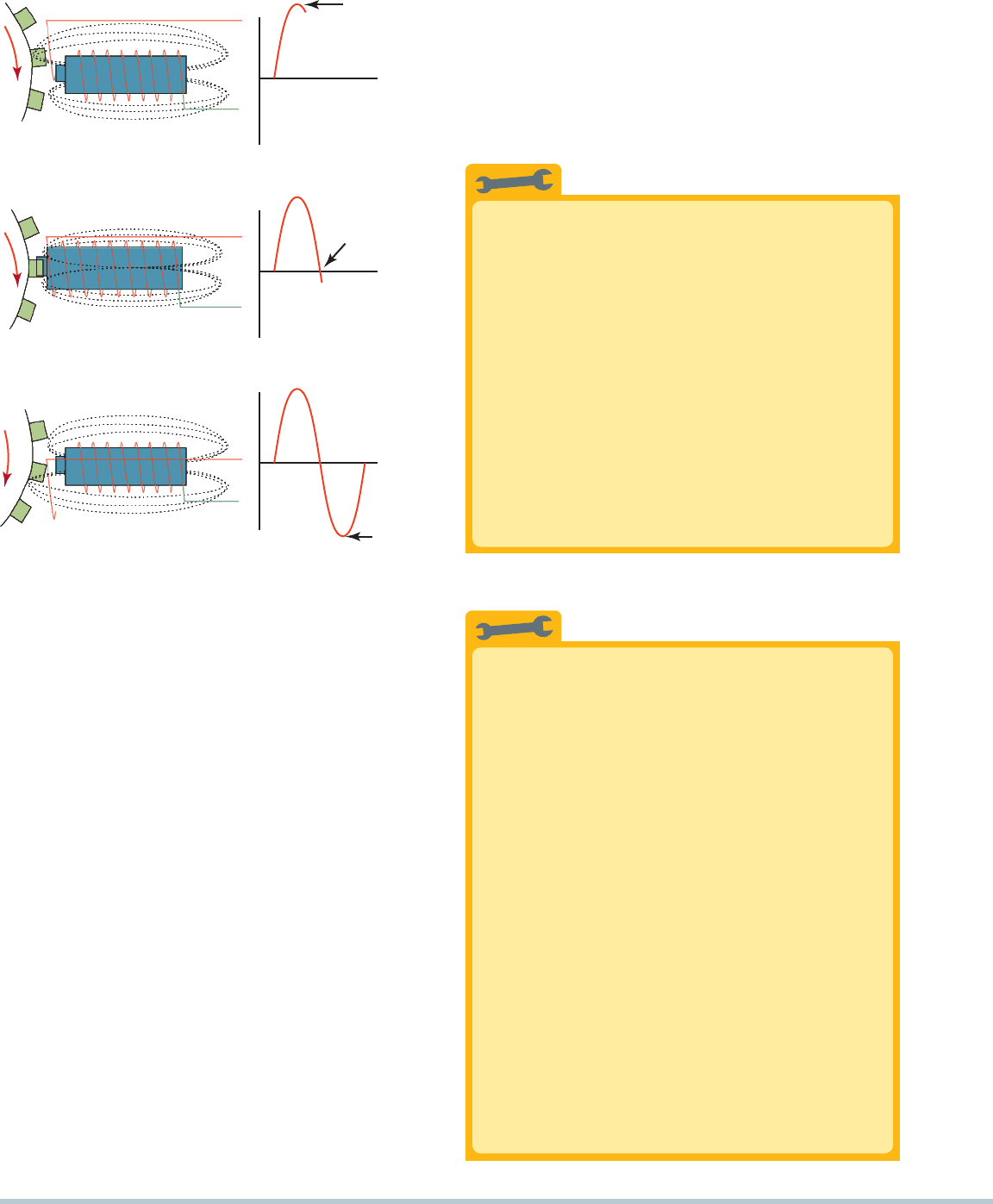
Hall-effect switch. This switch also uses a stationary sen-
sor and rotating trigger wheel (shutter). Unlike the magnetic
pulse generator, the Hall-effect switch requires a small input
voltage to generate an output or signal voltage. Hall effect
has the ability to generate a voltage signal in semiconduc-
tor material (gallium arsenate crystal) by passing current
through it in one direction and applying a magnetic field to
it at a right angle to its surface. If the input current is held
steady and the magnetic field fluctuates, an output voltage
is produced that changes in proportion to field strength.
Most Hall-effect switches in distributors have the following:
1. Hall element or device
2. Permanent magnet
3. Rotating ring of metal blades (shutters) similar to a trig-
ger wheel (Another method uses a stationary sensor
with a rotating magnet.)
SEE FIGURE 29–8 .
the switching is an electronic switch, such as a power transistor.
This power transistor can be found in the following locations:
Ignition control module (ICM) or igniter
PCM (computer)
NOTE: On some coil-on-plug (COP) systems, the ICM is part
of the ignition coil itself and is serviced as an assembly.
TRIGGERING The device that signals the switching of the
coil on and off or just on in most instances is called the trigger.
A trigger is typically a pickup coil in some distributor-type
ignitions and a crankshaft position sensor (CKP) on electronic
systems (waste spark and coil on plug). There are three types of
devices used for triggering:
1. Magnetic sensor
2. Hall-effect switch
3. Optical sensor
PRIMARY CIRCUIT OPERATION To get a spark out of
an ignition coil, the primary coil circuit must be turned on and off.
The primary circuit current switching is controlled by a transistor
(electronic switch) inside the ignition module (or igniter) or PCM
and is controlled by one of several devices, including the following:
Magnetic sensor. A simple and common ignition electronic
switching device is the magnetic pulse generator system.
This is a type of magnetic sensor, often called a magnetic
pulse generator or pickup coil, and is installed in the dis-
tributor housing. The pulse generator consists of a trigger
wheel (reluctor) and a pickup coil. The pickup coil consists of
an iron core wrapped with fine wire, in a coil at one end and
attached to a permanent magnet at the other end. The center
of the coil is called the pole piece. The pickup coil signal
358 CHAPTER 29
Some blades are designed to hang down, typically
found in Bosch and Chrysler systems, while others may
be on a separate ring on the distributor shaft, typically
found in General Motors and Ford Hall-effect distributors.
There are two types of Hall effect sensors used, including
the following:
When the shutter blade enters the gap between
the magnet and the Hall element, it creates a
magnetic shunt that changes the field strength
through the Hall element.
This analog signal is sent to a Schmitt trigger
inside the sensor itself, which converts the analog
signal into a digital signal. A digital (on or off) volt-
age signal is created at a varying frequency to the
ignition module or onboard computer.
SEE
FIGURE 29–9 .
Optical sensors. These use light from an LED and
a phototransistor to signal the computer. An inter-
rupter disc between the LED and the phototransis-
tor has slits that allow the light from the LED to
trigger the phototransistor on the other side of the
disc. Most optical sensors (usually located inside
the distributor) use two rows of slits to provide
individual cylinder recognition (low resolution) and
precise distributor angle recognition (high reso-
lution) signals that are used for cylinder misfire
detection.
SEE FIGURE 29–10 on page 360.
MAXIMUM
POSITIVE
SWING
OV
MAXIMUM
NEGATIVE
SWING
SWINGS
THROUGH
ZERO VOLTS
OV
OV
FIGURE 29–7 A magnetic sensor uses a permanent magnet
surrounded by a coil of wire. The notches of the crankshaft (or
camshaft) creates a variable magnetic field strength around
the coil and create an analog signal when the engine rotates.
When a metallic section is close to the sensor, the magnetic
field is stronger because metal is a better conductor of mag-
netic lines of force than air.
Optical Distributors Do Not Like Light
Optical distributors use the light emitted from LEDs
to trigger phototransistors. Most optical distributors
use a shield between the distributor rotor and the
optical interrupter ring. Sparks jump the gap from
the rotor tip to the distributor cap inserts. This shield
blocks the light from the electrical arc from interfer-
ing with the detection of the light from the LEDs.
If this shield is not replaced during service, the
light signals are reduced, and the engine may not
operate correctly.
SEE FIGURE 29–11 on page 360.
This can be difficult to detect because nothing
looks wrong during a visual inspection. Remember
that all optical distributors must be shielded between
the rotor and the interrupter ring.
TECH TIP
The Tachometer Trick
When diagnosing a no-start or intermediate missing
condition, check the operation of the tachometer. If the
tachometer does not indicate engine speed (no-start
condition) or drops toward zero (engine missing), then
the problem is due to a defect in the primary ignition
circuit. The tachometer gets its signal from the pulsing
of the primary winding of the ignition coil. The follow-
ing components in the primary circuit could cause the
tachometer to not work when the engine is cranking:
• Pickup coil
• Crankshaft position sensor
• Ignition module (igniter)
• Coil primary wiring
If the vehicle is not equipped with a tachometer,
use a scan tool to look at engine RPM. The results
are as follows:
• No or an unstable engine RPM reading means the
problem is in the primary ignition circuit.
• A steady engine RPM reading means the
problemis in the secondary ignition circuit or is a
fuel-related problem.
TECH TIP
359
1 KΩ
+5 V
SIGNAL
GROUND
0 V
+5 V
TRIGGER
WHEEL
HALL-EFFECT
SENSOR
FIGURE 29–8 A Hall-effect sensor produces a digital on-off voltage signal whether it is used with a blade or a notched wheel.
HALL-EFFECT REFERENCE
CAMSHAFT SENSOR
REFERENCE
FOR CYLINDER #5
REFERENCE
FOR CYLINDER #4
REFERENCE
FOR CYLINDER #6
REFERENCE
FOR CYLINDER #3
REFERENCE
FOR CYLINDER #2
REFERENCE FOR CYLINDER #1
HALL-EFFECT CRANKSHAFT
POSITION SENSOR
TORQUE CONVERTER
DRIVE PLATE
CRANK SENSOR
ELECTRICAL
CONNECTOR
PAPER
SPACER
CAM SENSOR
ELECTRICAL
CONNECTOR
CRANK
CAM
TDC-2
O-RING
TDC-3 TDC-4
TDC-5
TDC-6 TDC-1
PAPER
SPACER
SLOTS
FIGURE 29–9 Some Hall-effect sensors look like magnetic sensors. This Hall-effect camshaft reference sensor and
crankshaft position sensor have an electronic circuit built in that creates a 0- to 5-volt signal as shown at the bottom. These
Hall-effect sensors have three wires: a power supply (8 volts) from the computer (controller), a signal (0 to 5 volts), and a
signal ground.
360 CHAPTER 29
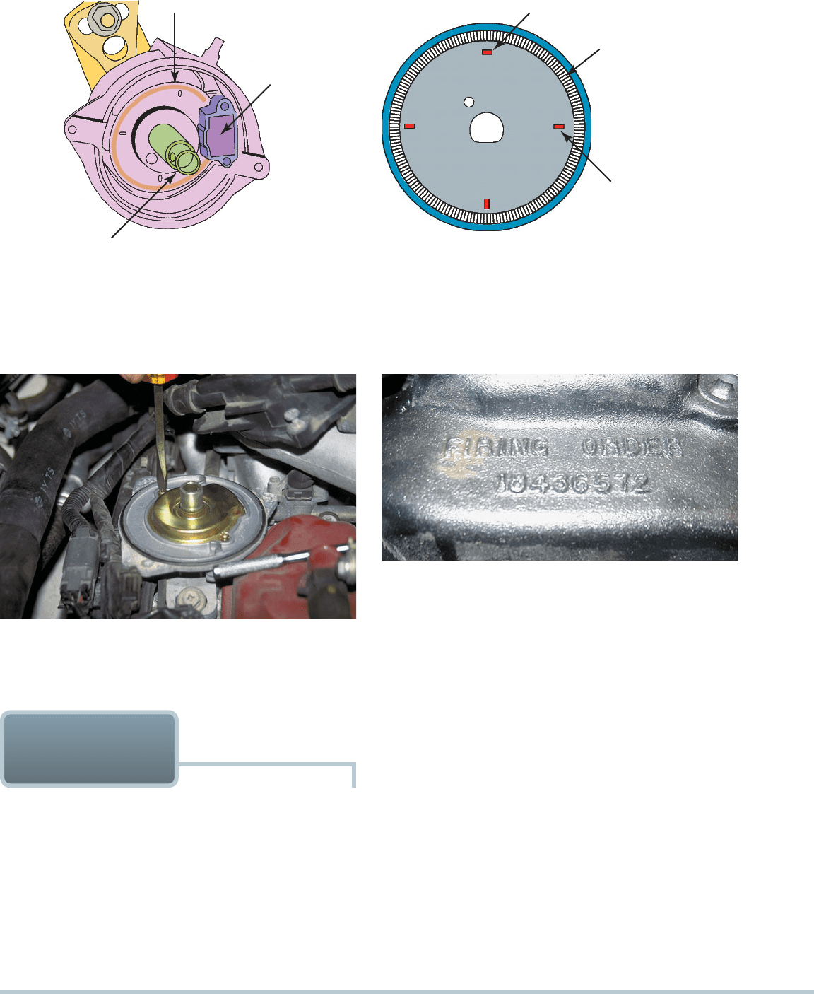
ROTOR PLATE
CRANK ANGLE
SENSOR
ROTOR SHAFT
(a)
FIGURE 29–10 (a) Typical optical distributor. (b) Cylinder I slit signals the computer the piston position for cylinder I. The
1-degree slits provide accurate engine speed information to the PCM. Optical sensors generate digital (on and off) signals.
(b)
ROTOR PLATE
180° SIGNAL SLIT FOR NO. 1 CYLINDER
180°
SIGNAL SLIT
1° SIGNAL SLIT
FIGURE 29–11 A light shield is being installed on an optical
distributor before the rotor is attached.
FIGURE 29–12 The firing order is cast or stamped on the in-
take manifold on most engines that have a distributor ignition.
First, to trigger the ignition control module by the use of
the rotating distributor shaft
Second, by rotating the rotor to distribute the high-
voltage spark to the individual spark plugs
FIRING ORDER Firing order means the order that the
spark is distributed to the correct spark plug at the right
time. The firing order of an engine is determined by crank-
shaft and camshaft design. The firing order is determined
by the location of the spark plug wires in the distributor cap
of an engine equipped with a distributor. The firing order is
often cast into the intake manifold for easy reference.
SEE
FIGURE 29–12 .
Service information also shows the firing order and the di-
rection of the distributor rotor rotation as well as the location of
the spark plug wires on the distributor cap.
PURPOSE AND FUNCTION The purpose of a distributor
is to distribute the high-voltage spark from the output terminal
of the ignition coil to the spark plugs for each cylinder. A gear
or shaft drives the distributor that is connected to the camshaft
and is driven at camshaft speed. Most distributor ignition sys-
tems also use a sensor to trigger the ignition control module.
OPERATION OF DISTRIBUTOR IGNITION The distrib-
utor is used twice in most ignition systems that use a distributor:
DISTRIBUTOR
IGNITION