Groshong Richard H. 3-D Structural Geology(Second Edition)
Подождите немного. Документ загружается.

291
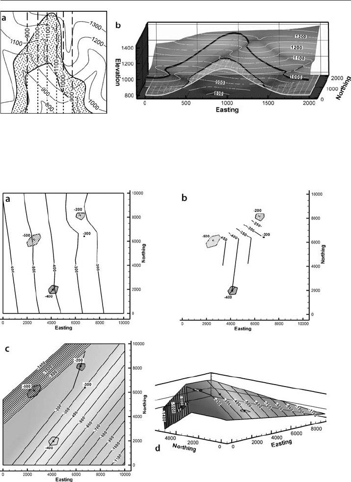
Fig. 10.9. Correct interpretation of the map in Fig. 10.8. a Structure contours on the base of the bed,
based on knowledge that the fold axis trends north–south with zero plunge (after Weijermars 1997).
Long dashes indicate contours below ground, short dashes indicate contours projected above ground.
b 3-D view of fold. Trace of the upper boundary is shown on the topography. The lower boundary is
rendered as an outcrop trace and as a 3-D mesh
Fig. 10.10. Structure contour maps based on the four labeled points. Dips are known at the 3 points
surrounded by polygons. a Kriged contouring based on elevations. b Triangulation contouring based
on elevations. c Dip-domain map based on contour direction and spacing from 3 known bedding atti-
tudes. d 3-D oblique view NE of c
10.3 · Trend Incompatibilities

292 Chapter 10 · Quality Control
derived by applying different computer contouring techniques to identical data.
If dip information is available from even a few locations, the derived contour direc-
tions and spacings (Sect. 3.6.1) greatly constrain the interpretation. The map in
Fig. 10.10c has been produced by extending the known dips in 3-D until they inter-
sect to define boundaries with the adjacent domains, then contouring the resulting
structure by triangulation. The map so constructed (Fig. 10.10c,d) agrees perfectly
with the known dips.
Any conflict between the structure contours and the local bedding attitudes should
be investigated. Local attitude measurements with a compass in outcrop or from a
dipmeter in the subsurface can be accurate yet not reflect the map
-scale structure. Small-
scale bedding variations, cross bedding, or minor folding, can all lead to bedding atti-
tudes that diverge from the trend that should appear on the structure contour map.
The regional trend will be clearer, in spite of any small
-scale variability of the bedding
attitudes, if the fold axis is found using multiple attitude measurements (Sect. 5.2).
10.4
Bed Thickness Anomalies
Many quality-control measures are ultimately based on the concept that bed thick-
nesses should remain constant or be smoothly varying. This concept is applied as a
quality control tool to the compatibility between multiple horizons on maps and cross
sections, the internal consistency of composite
-surface maps, and the geological like-
lihood of the growth history given by the expansion index.
10.4.1
Compatibility between Structure Contour Maps
The structure of nearby stratigraphic horizons is usually fairly similar. If unit thick-
nesses are approximately constant, the shapes of nearby horizons will be nearly the
same. The compatibility of maps on closely spaced horizons is indicated by structure
contours that are nearly parallel (Fontaine 1985) and separated by approximately con-
stant distances (in gently dipping beds). A significant difference in trends on adjacent
surfaces suggests a possible misinterpretation of one or both of the surfaces. The struc-
ture contours on different horizons cannot intersect without implying a structural or
stratigraphic discontinuity. Only faults and unconformity surfaces can cut across strati-
graphic boundaries.
Mapping different horizons independently can easily lead to incompatible surfaces.
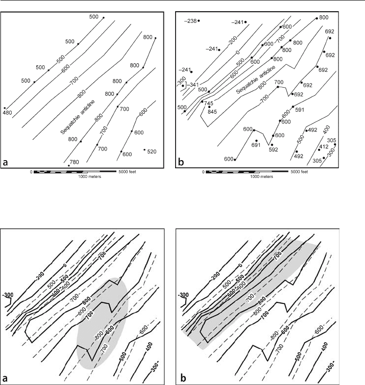
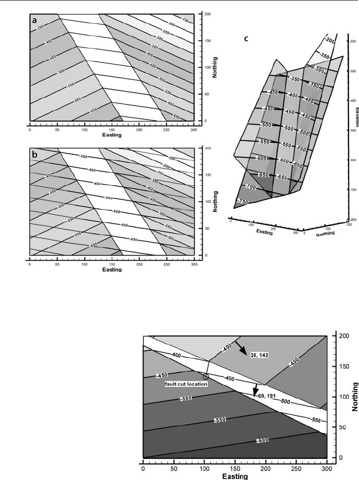
Figure 10.11 shows structure contour maps on two closely spaced horizons on the same
part of the Sequatchie anticline. In this example more control data were generated for
the lower surface (Fig. 10.11b) by means of vertical projection (Sect. 3.6.2). To deter-
mine if the maps are compatible, they are superimposed (Fig. 10.12). The superposed
contours are approximately parallel and so are compatible by this criterion, except in
the shaded region of second
-order folding on the southeast limb of the major anticline
(Fig. 10.12a). Disharmonic folding is implied by the folds confined to the Mtfp. This
may be geologically reasonable if the mechanical stratigraphy is appropriate (Sect. 1.5.1)
but should be checked.
293
A comparison between elevations of the two maps in Fig. 10.11 reveals a fatal flaw
in the interpretation: the upper stratigraphic surface lies below the lower stratigraphic
surface in the shaded area of Fig. 10.12b. This indicates a glaring lack of compatibility
between the two surfaces. Usually it will be the map with the lesser amount of control
that should be corrected. A cross section would also reveal this problem and make it
easy to visualize, one of the reasons that cross sections should always be part of the
quality control process.
Fig. 10.11. Structure contours on adjacent horizons. Control points are labeled. Contour interval is 100 ft.
a Top of the Mpm. b Structure contour map on the top of the Mtfp, 108 ft stratigraphically below the Mpm
Fig. 10.12. Testing for compatible surfaces by superimposing structure contour maps. Structure con-
tour map of the top Mpm (dashed contours) overlain on the composite map of the top Mtfp (solid
contours). a Shaded area is a zone of contour shape incompatibility. b Shaded area shows approximate
area where the stratigraphically higher surface (Mpm, dashed lines) lies below the stratigraphically
lower surface (Mtfp, solid lines)
10.4 · Bed Thickness Anomalies
294 Chapter 10 · Quality Control
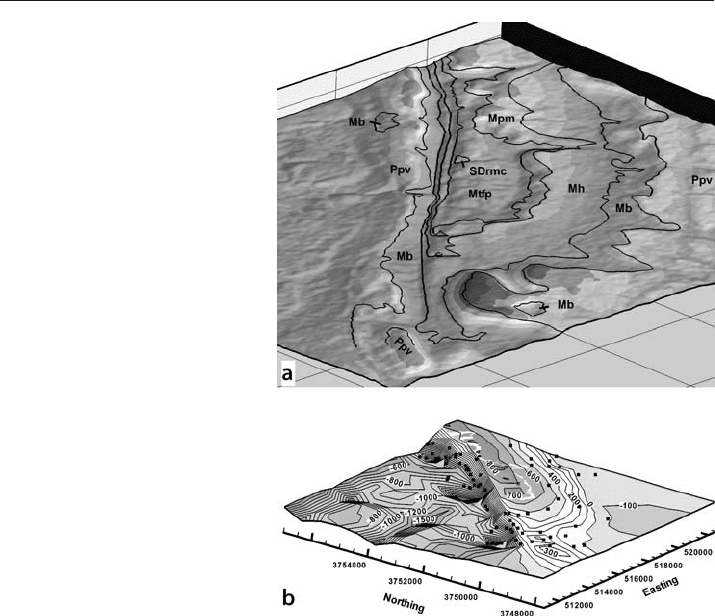
A composite surface map (Sect. 3.6.2) provides a method for the simultaneous testing
of a complete geological map for internal consistency. It is very difficult to determine by
inspection alone whether the outcrop traces on a geological map (e.g., Fig. 10.13a) are
consistent with one another. The composite surface map of a representative horizon pro-
vides such a test. If the composite
-surface map shows a realistic structure, without unex-
plained peaks and valleys, as in Fig. 10.13b, then the combined data are internally consis-
tent. Because outcrop trace locations, dips and thicknesses all work together to produce
the final map, all of this information is tested by the composite surface map.
10.4.2
Compatibility of Thicknesses on Cross Sections
A cross section is a powerful tool for checking and improving the structural interpreta-
tion presented on an outcrop map or on multiple structure contour maps. First be sure
the cross section matches the map from which it was constructed. In section view, poorly
controlled map horizons may be improved with information from other horizons
(c.f. Sect. 6.4). Errors in mapping on one horizon can be recognized as incompatibilities
with the geometry of horizons above or below. Many of the mapping pitfalls noted pre-
Fig. 10.13.
Compatibility of geological
contacts in outcrop. a Geo-
logical map of the southern
Sequatchie anticline at Blount
Springs, Alabama on a 30 m
DEM base from Fig. 2.4. Ob-
lique view to NE. Distance
between grid lines, 1 km.
Thick black lines are geologic
contacts. b Composite struc-
ture contour map of the top
Mtfp, oblique view to NE (from
Fig. 3.23b)
295
viously and their correct interpretations are immediately obvious on a cross section. A
valid cross section must be compatible with the structure laterally adjacent to the section
as well. Accurate interpretation in three dimensions is demonstrated by means of maps
and cross sections that are each internally consistent and consistent with each other.
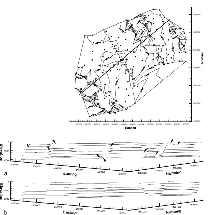
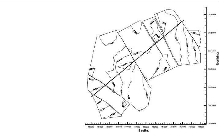
The preliminary structure contour map in Fig. 10.14 shows excessively wiggly con-
tours and some trends that might represent faults. A cross section of the preliminary
contour maps on multiple horizons is constructed by slicing the maps. The section
(Fig. 10.15a) shows numerous thickness anomalies and discontinuities that can be resolved
by inserting faults (Fig. 10.15b). Once the faults are mapped and the marker surfaces re
-
mapped (Sect. 8.3.2), the thickness anomalies disappear, and the new marker-surface map
is much simpler (Fig. 10.16).
Fig. 10.14.
Preliminary map of top Mary
Lee structure contours in the
southeast Deerlick Creek co-
albed methane field, Black
Warrior Basin, Alabama. Data
from Groshong et al. (2003b).
Control points are squares.
Easting and northing in
meters, elevations in ft. Trace
of cross section in Fig. 10.15
is shown
Fig. 10.15. Cross section of SE Deerlick Creek coalbed methane field. Horizontal view to NW. No verti-
cal exaggeration. Easting and northing in meters, elevations in ft. a Preliminary interpretation of all
horizons. Arrows point to thickness anomalies. b After locating faults and re-mapping
10.4 · Bed Thickness Anomalies
296 Chapter 10 · Quality Control
10.4.3
Realistic Growth History
The growth sediments, deposited during deformation, contain a record of the struc-
tural evolution. The implied evolution must be compatible with the regional struc-
tural style and evolution. Apparent inconsistencies in the indicated geological evolu-
tion may indicate errors in the interpretation. The expansion index plot across a fault
(Sect. 7.7.4) is very helpful in recognizing and fixing this type of problem. The appro-
priate form of the plot is determined from the local structural style. For example, in an
extensional region, a reasonable expectation is that the sense of displacement on nor-
mal faults does not reverse and, consequently, that the expansion index must always be
greater than one. A value of less than one means that the downthrown side received
less sediment than the upthrown side which, in turn, implies that the downthrown side
was high (upthrown) during the interval having an E < 1.0. In this situation, an E < 1.0
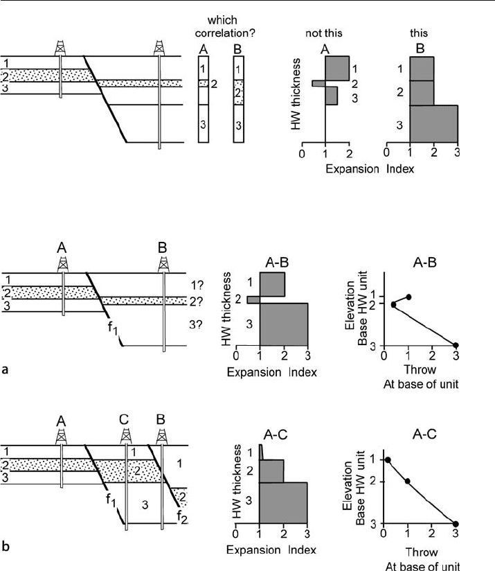
could indicate a miscorrelation, either of the units or of the fault cuts. In Fig. 10.17, if
the top three units are correlated, E is less than one in unit 2. A better interpretation is
that the thin unit 2 on the hangingwall is part of a thicker interval that correlates with
unit 2 on the footwall (interpretation 2). Another possibility is that the abnormally thin
unit in well B on the downthrown side of a fault has been truncated by another fault
(Fig. 10.18a). Inserting fault f
2
at the proper location (Fig. 10.18b) results in the correct
form of the expansion
-index diagram. The expansion index increases steadily down-
ward for the reinterpreted fault blocks.
The growth history should agree with the stratigraphic separation on the fault. Within
the growth interval on a normal fault, the separation is expected to increase down the
dip. The throw across the fault can be plotted against depth (Fig. 10.18). A misinter-
Fig. 10.16.
Top Mary Lee structure contour
map (same data as Fig. 10.14)
after reinterpretation of all
map horizons to include faults.
Easting and northing in meters,
elevations in ft
297
Fig. 10.17. Use of the expansion index to test unit correlations. An expansion index of less than one
implies reverse fault movement or a miscorrelation across a normal fault
Fig. 10.18. Presence of a fault interpreted from anomalies in the expansion index and vertical separa-
tion. a A misinterpretation of the hangingwall of fault f
1
that gives an expansion index of less than one
for unit 2 and a fault throw that decreases and then increases with depth. b The anomalous thinness of
unit 2 in well B is explained by normal fault f
2
. C is a well that would penetrate an unfaulted section in
the hangingwall of the fault f
1
preted growth stratigraphy (Fig. 10.18a) shows the separation to decrease downward
and then to increase again. The correct interpretation (Fig. 10.18b) shows a continuing
increase of vertical separation downward.
10.4 · Bed Thickness Anomalies
298 Chapter 10 · Quality Control
10.5
Unlikely or Impossible Fault Geometries
It is surprisingly easy to create interpretations that include impossible or at least very
unlikely 3
-D fault geometries. Faults placed on single-horizon structure-contour maps
or on geological outcrop maps without regard to the implied 3
-D fault shape are the most
likely to cause problems. The quality of a fault interpretation can be assessed using the
implied fault shape and the cutoff
-line geometry of hangingwall and footwall. A final
quality
-control issue is the distinction between a fault and an axial surface.
10.5.1
Fault Shape
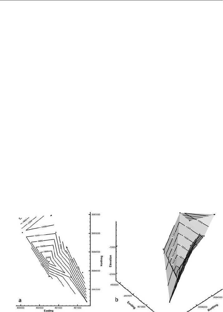
Fault surfaces should always be mapped. The shape of an undeformed fault should be
planar, smoothly curved, or have a stair
-step shape. A very irregular fault (Fig. 10.19)
probably cannot move and so is unlikely to be a correct interpretation unless the fault
has been folded by a later event.
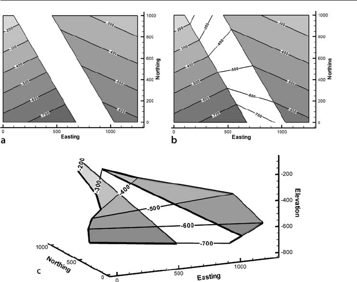
Structure contour maps of faulted horizons are commonly shown without contours
on the faults. Contouring the implied fault surface, by matching elevations across the
fault, is a very simple and effective test of the interpretation. Incorrect interpretations
of the fault
-bedding relationships will show unreasonable or impossible contour pat-
terns for the fault surface. The implied fault surface in Fig. 10.20 has a spiral shape,
possible perhaps, but not very likely. In more complex situations, crossing contours
may occur on the implied fault, an even less likely result.
Implied structure contours may reveal problems in addition to unlikely fault shapes.
In Fig. 10.21a the implied structures on the fault are parallel and so are reasonable. But
once the fault contours are extended across the map (Fig. 10.21b) a problem becomes
Fig. 10.19. Map of two faults from the Deerlick Creek area (Fig. 7.32) interpreted as being a single fault.
Squares are the positions of fault cuts, contours are on the fault surface. a Structure contour map, syncli-
nal shape is unreasonable. b 3-D view to the NW of the inferred synclinal fault
299
Fig. 10.20. Interpretation of unlikely fault geometry from implied structure contours. a Structure contour
map of offset marker without contours on fault. b The implied fault contours found by connecting equal ele-
vations of the hangingwall and footwall bed cutoffs. c 3-D view to NE showing the implied spiral fault shape
apparent. The map shows the marker bed to be above the fault on both sides of the fault
gap. Normally an offset bed will occur on both sides of the fault. This is not required for
a fault where erosion has removed beds from one side, but otherwise is anticipated.
The 3
-D view (Fig. 10.21c) makes it clear that both segments of the marker bed are in
the hangingwall of the fault. Either the map in Fig. 10.21a is wrong or the fault has
truncated a steeply plunging synform, the trough of which has yet to be located. Find-
ing the synclinal hinge of the marker
-bed in the footwall would validate the map.
10.5.2
Fault Separation
The stratigraphic separation from a fault cut in a well must agree with the heave and
throw shown by the structure contour map of the faulted surface. Suppose the well
that cuts the normal fault at the location shown in Fig. 10.22 has a stratigraphic sepa-
ration of 75 m, is this consistent with the map? The map indicates a heave of 24.6 m
and a throw of 64.5 m (Sect. 8.2). From Eqs. 8.1 or 8.2, the stratigraphic separation on
the fault should be 47.6 m, a significant difference. The alternative strategy is to find
10.5 · Unlikely or Impossible Fault Geometries
300 Chapter 10 · Quality Control
Fig. 10.21. Questionable relationship between marker bed and fault. a Structure contour map of marker bed
with contours across fault gap. Fault resembles a simple normal fault with missing section. b Fault contours
extended across the map. c 3-D oblique view shows both segments of the marker belong to the hangingwall
Fig. 10.22.
Structure contour map of a
normal fault (from Fig. 8.5a)
the heave and throw from Eqs. 7.5–7.6 or 7.7–7.8 and compare to the values on the
map. The discrepancy is revealed by either method and requires that the fault cut in-
terpretation be changed or the map reinterpreted.
